EP1631055A2 - Bilderzeugungsgerät - Google Patents
Bilderzeugungsgerät Download PDFInfo
- Publication number
- EP1631055A2 EP1631055A2 EP05015918A EP05015918A EP1631055A2 EP 1631055 A2 EP1631055 A2 EP 1631055A2 EP 05015918 A EP05015918 A EP 05015918A EP 05015918 A EP05015918 A EP 05015918A EP 1631055 A2 EP1631055 A2 EP 1631055A2
- Authority
- EP
- European Patent Office
- Prior art keywords
- resolution
- frame
- unit
- distribution information
- imaging
- Prior art date
- Legal status (The legal status is an assumption and is not a legal conclusion. Google has not performed a legal analysis and makes no representation as to the accuracy of the status listed.)
- Granted
Links
- 238000003384 imaging method Methods 0.000 title claims abstract description 105
- 239000013598 vector Substances 0.000 claims abstract description 76
- 238000006243 chemical reaction Methods 0.000 claims description 29
- 230000006835 compression Effects 0.000 abstract description 17
- 238000007906 compression Methods 0.000 abstract description 17
- 230000003287 optical effect Effects 0.000 description 5
- 238000012986 modification Methods 0.000 description 2
- 230000004048 modification Effects 0.000 description 2
- 238000005452 bending Methods 0.000 description 1
- 238000010586 diagram Methods 0.000 description 1
- 230000000694 effects Effects 0.000 description 1
- 230000012447 hatching Effects 0.000 description 1
Images




Classifications
-
- H—ELECTRICITY
- H04—ELECTRIC COMMUNICATION TECHNIQUE
- H04N—PICTORIAL COMMUNICATION, e.g. TELEVISION
- H04N19/00—Methods or arrangements for coding, decoding, compressing or decompressing digital video signals
- H04N19/50—Methods or arrangements for coding, decoding, compressing or decompressing digital video signals using predictive coding
- H04N19/503—Methods or arrangements for coding, decoding, compressing or decompressing digital video signals using predictive coding involving temporal prediction
- H04N19/51—Motion estimation or motion compensation
- H04N19/513—Processing of motion vectors
-
- H—ELECTRICITY
- H04—ELECTRIC COMMUNICATION TECHNIQUE
- H04N—PICTORIAL COMMUNICATION, e.g. TELEVISION
- H04N19/00—Methods or arrangements for coding, decoding, compressing or decompressing digital video signals
- H04N19/42—Methods or arrangements for coding, decoding, compressing or decompressing digital video signals characterised by implementation details or hardware specially adapted for video compression or decompression, e.g. dedicated software implementation
- H04N19/436—Methods or arrangements for coding, decoding, compressing or decompressing digital video signals characterised by implementation details or hardware specially adapted for video compression or decompression, e.g. dedicated software implementation using parallelised computational arrangements
-
- H—ELECTRICITY
- H04—ELECTRIC COMMUNICATION TECHNIQUE
- H04N—PICTORIAL COMMUNICATION, e.g. TELEVISION
- H04N19/00—Methods or arrangements for coding, decoding, compressing or decompressing digital video signals
- H04N19/50—Methods or arrangements for coding, decoding, compressing or decompressing digital video signals using predictive coding
- H04N19/503—Methods or arrangements for coding, decoding, compressing or decompressing digital video signals using predictive coding involving temporal prediction
- H04N19/51—Motion estimation or motion compensation
- H04N19/53—Multi-resolution motion estimation; Hierarchical motion estimation
-
- H—ELECTRICITY
- H04—ELECTRIC COMMUNICATION TECHNIQUE
- H04N—PICTORIAL COMMUNICATION, e.g. TELEVISION
- H04N19/00—Methods or arrangements for coding, decoding, compressing or decompressing digital video signals
- H04N19/50—Methods or arrangements for coding, decoding, compressing or decompressing digital video signals using predictive coding
- H04N19/587—Methods or arrangements for coding, decoding, compressing or decompressing digital video signals using predictive coding involving temporal sub-sampling or interpolation, e.g. decimation or subsequent interpolation of pictures in a video sequence
-
- H—ELECTRICITY
- H04—ELECTRIC COMMUNICATION TECHNIQUE
- H04N—PICTORIAL COMMUNICATION, e.g. TELEVISION
- H04N19/00—Methods or arrangements for coding, decoding, compressing or decompressing digital video signals
- H04N19/50—Methods or arrangements for coding, decoding, compressing or decompressing digital video signals using predictive coding
- H04N19/59—Methods or arrangements for coding, decoding, compressing or decompressing digital video signals using predictive coding involving spatial sub-sampling or interpolation, e.g. alteration of picture size or resolution
-
- H—ELECTRICITY
- H04—ELECTRIC COMMUNICATION TECHNIQUE
- H04N—PICTORIAL COMMUNICATION, e.g. TELEVISION
- H04N19/00—Methods or arrangements for coding, decoding, compressing or decompressing digital video signals
- H04N19/60—Methods or arrangements for coding, decoding, compressing or decompressing digital video signals using transform coding
- H04N19/61—Methods or arrangements for coding, decoding, compressing or decompressing digital video signals using transform coding in combination with predictive coding
-
- H—ELECTRICITY
- H04—ELECTRIC COMMUNICATION TECHNIQUE
- H04N—PICTORIAL COMMUNICATION, e.g. TELEVISION
- H04N23/00—Cameras or camera modules comprising electronic image sensors; Control thereof
- H04N23/45—Cameras or camera modules comprising electronic image sensors; Control thereof for generating image signals from two or more image sensors being of different type or operating in different modes, e.g. with a CMOS sensor for moving images in combination with a charge-coupled device [CCD] for still images
-
- H—ELECTRICITY
- H04—ELECTRIC COMMUNICATION TECHNIQUE
- H04N—PICTORIAL COMMUNICATION, e.g. TELEVISION
- H04N23/00—Cameras or camera modules comprising electronic image sensors; Control thereof
- H04N23/95—Computational photography systems, e.g. light-field imaging systems
- H04N23/951—Computational photography systems, e.g. light-field imaging systems by using two or more images to influence resolution, frame rate or aspect ratio
Definitions
- the present invention relates to an imaging apparatus that shoots the moving image of a subject.
- the imaging apparatus which shoots the moving image compresses a plurality of frames which are sequentially outputted from an imaging device in various ways, in order to reduce the amount of data when recording.
- An internal circuit which performs compression processing takes in the frames in the same resolution in constant time intervals, and sequentially performs intra-frame compression processing and inter-frame compression processing (refer to Japanese Unexamined Patent Application Publication No. Hei 9-23405, for example).
- the above-mentioned imaging apparatus performs the compression processing by taking in the frames with the same resolution. Therefore, when recording resolution is increased in order to obtain the moving image of high definition, the resolution of each frame increases, the amount of data to be handled during the compression processing increases, and processing speed lowers, which result in a slow imaging frame rate.
- the imaging apparatus includes a first imaging unit capturing an image of a subject and outputting a frame in a first resolution in first time intervals, a second imaging unit capturing the image of the subject and outputting a frame in second resolution which is higher than the first resolution in second time intervals that are longer than the first time intervals, a detecting unit detecting motion vectors between adjacent frames output from the first imaging unit and outputting the motion vectors as vector distribution information in the first resolution, a converting unit converting the vector distribution information in the first resolution into vector distribution information in the second resolution, and a recording unit recording on a storage media the vector distribution information in the second resolution and the frames output from the second imaging unit.
- the imaging apparatus further includes a generating unit generating a difference frame from a difference between a predictive frame predicted by motion compensation using the vector distribution information in the first resolution and the frame output from the first imaging unit.
- the converting unit further performs conversion processing of the difference frame in the first resolution which is generated by the generating unit into a difference frame in the second resolution, in addition to the conversion processing of the resolution of the vector distribution information.
- the recording unit further records the difference frame in the second resolution on the storage media, in addition to the vector distribution information in the second resolution and the frames output from the second imaging unit.
- the detecting unit divides each frame output from the first imaging unit into a plurality of small blocks and detects the motion vector for each of the small blocks, and the converting unit performs the conversion processing by performing conversion processing for each of the small blocks in the vector distribution information in the first resolution, and when focusing on any one of the small blocks, performs said conversion processing by adding the motion vectors around the focused block to the motion vector of the focused block.
- the recording unit encodes and records the vector distribution information in the second resolution and the frames output from the second imaging unit by an MPEG system.
- the recording unit encodes and records the vector distribution information in the second resolution, the frames which are outputted from the second imaging unit, and the difference frame in the second resolution by an MPEG system.
- the first imaging unit is also used as an AE and/or AF sensing unit
- the second imaging unit is also used as an imaging unit which photographs still images.
- An imaging apparatus 10 is provided with two imaging devices 11 and 12, as shown in Fig. 1.
- the imaging devices 11 and 12 are CCD imaging devices, for example.
- Light from a subject falls inside the imaging apparatus 10 via a shooting lens 13 and subjected to optical path division in two directions via a half mirror 14. Thereafter, one transmitting light directly falls on the imaging device 12, and the other reflected light falls on the imaging device 11 via a mirror 15 and a correcting lens 16.
- the image of the subject is formed on each imaging surface of the imaging devices 11 and 12.
- the correcting lens 16 is an optical system for correcting a difference in size between the imaging devices 11 and 12 and correcting a difference in optical path length from the shooting lens 13 to the imaging devices 11 and 12.
- one frame F 2 is outputted from the imaging device 12 in the high resolution every time the five frames F 1 are outputted from the imaging device 11 in the low resolution. Further, the frame F 1 in the low resolution is outputted simultaneously with the timing when the frame F 2 in the high resolution is outputted. Accordingly, the arrangement of the frames F 1 and F 2 outputted from the two imaging devices 11 and 12 in a time series order is as shown in Fig. 3. The frames F 1 and F 2 are outputted simultaneously at the time t 1 , only the frame F 1 in the low resolution is outputted at the times t 2 to t 5 , and the frames F 1 and F 2 are outputted simultaneously again at the time t 6 . It should be noted that the same subject is reflected in the frames F 1 and F 2 which are outputted at the same time.
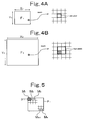
- one pixel in the frame F 1 in the low resolution (bold solid line frame in Fig. 4(A)) corresponds to four pixels in the frame F 2 in the high resolution (bold solid line frame in Fig. 4(B)).
- one pixel in the frame F 2 in the high resolution corresponds to a dot hatching area.
- the imaging apparatus 10 of this embodiment is provided with A/D conversion parts 17 and 18, a data processing part 19, a compressing part 20 and a recording part 21 as shown in Fig. 1, in addition to the above two imaging devices 11 and 12 having different characteristics. Further, the data processing part 19 is constituted of a motion detecting part 9A and a resolution conversion part 9B. Furthermore, the imaging apparatus 10 is equipped with an external storage media 22 via the recording part 21.
- the external storage media 22 is a memory card or the like which is removable from the imaging apparatus 10.
- the two kinds of the frames (that is, the frame F 1 in the low resolution and the frame F 2 in the high resolution) having the different resolution are taken from the imaging devices 11 and 12 into an internal circuit (17 to 21) of the imaging apparatus 10.
- the frames F 1 and F 2 from the imaging devices 11 and 12 are respectively converted from analog signals into digital signals via the A/D conversion parts 17 and 18, and outputted to the data processing part 19 and the compressing part 20.
- predetermined data processing is performed by the data processing part 19 and the compressing part 20 so as to reduce a data amount to be recorded on the external storage media 22.
- the data processing in the compressing part 20 is intra-frame compression processing.
- I Picture Intra-Picture
- MPEG2 MPEG2 and the like, for example
- the data processing in the data processing part 19 is inter-frame arithmetic processing.
- each of the frames F 1 in the low resolution is divided into a plurality of small blocks 31, as shown in Fig. 5.
- Each small block 31 includes a plurality of pixels.
- motion vectors M 1 , M 2 , ..., M N of the respective small blocks 31 are detected between adjacent frames (between the frame F 1 at the time t 1 and the frame F 1 at the time t 2 in Fig. 3, for example).
- motion vectors M 1 , M 2 , ..., M N are brought into correspondence with positional information of the small blocks 31 in the frame F 1 in the low resolution.
- the motion detecting part 9A detects the motion vectors M 1 , M 2 , ..., M N of the respective small blocks 31, it outputs the motion vectors M 1 , M 2 , ..., M N to the resolution conversion part 9B as vector distribution information in the low resolution (Fig. 5).
- the resolution conversion part 9B performs conversion processing of the vector distribution information in the low resolution (Fig. 5) which is inputted from the motion detecting part 9A into vector distribution information in the high resolution (Fig. 6).
- positional information of small blocks 32 in the frame F 2 in the high resolution is brought into correspondence with motion vectors M 1 , M 2 , ..., M N of the respective small blocks 32.
- the small block 32 in the frame F 2 in the high resolution has the same number of pixels as the small block 31 in the frame F 1 in the low resolution.
- one small block 31 in the frame F 1 in the low resolution corresponds to the four small blocks 32 in the frame F 2 in the high resolution, similarly to the correspondence of the pixels as shown in Figs. 4.
- the resolution conversion processing is performed for each of the small blocks 31 in the vector distribution information in the low resolution (Fig. 5). Focusing on a motion vector M K of the small block 31 at the position (i, j) in the frame F 1 in the low resolution as shown in Fig. 7, for example, the motion vector M K is applied to the four small blocks 32 at the same position (i, j) in the frame F 2 in the high resolution.
- the position coordinate in the frame F 2 in the high resolution represents the four small blocks (small blocks in the frame F 1 in the low resolution) consisting of two vertical and horizontal blocks as a unit. Namely, the motion vector M K which is the same as the small block 31 is assigned to the four small blocks 32.
- the same conversion processing is performed for each of the motion vectors M 1 , M 2 , ..., M N of the vector distribution information in the low resolution (Fig. 5), so that the vector distribution information in the high resolution can be generated as shown in Fig. 6.
- the resolution conversion part 9B After generating the vector distribution information in the high resolution (Fig. 6), the resolution conversion part 9B outputs it to the recording part 21.
- the compression processing is performed as follows by regarding GOP (Group of Pictures) consisting of the I Picture, P Picture and B Picture as one unit.
- the I Picture is the frame which is subjected to intra-frame encoding without using preceding/succeeding prediction.
- the so-called motion-compensated inter-frame prediction is performed, in which the prediction of the image in the next frame is made by shifting the image by the determined motion vectors in a motion area of the image.
- a prediction image is generated using the past image and the determined motion vectors.
- the prediction image is generated using the temporally preceding/succeeding images and the determined motion vectors.
- the image data corresponding to the I Picture can be obtained by the imaging device 12. Further, the motion vectors can be determined from the image data by the imaging device 11.
- the image data with the high resolution which is obtained by the imaging device 12 is subjected to the motion-compensated inter-frame prediction using thus-obtained motion vectors, so that the images corresponding to the P Picture and the B Picture can be obtained. Namely, it is possible to reproduce the image corresponding to the I Picture and the images corresponding to the P Picture and the B Picture once the image compression data in the high resolution obtained by the imaging device 12 and the motion vectors determined from the image data by the imaging device 11 are recorded.
- the two kinds of the frames that is, the frame F 1 in the low resolution and the frame F 2 in the high resolution
- the predetermined intra-frame compression processing and inter-frame compression processing are performed by the data processing part 19 and the compressing part 20, and the vector distribution information in the high resolution (Fig. 6) and the frames F 2 are recorded, so that a moving image of high definition can be obtained.
- the imaging apparatus 10 of this embodiment it is possible to cut out and use the frame F 2 in the high resolution which is outputted from the imaging device 12 as it is as a still image (continuous shooting image) of the high definition.
- the imaging apparatus 10 of this embodiment it is possible to use the imaging device 11 also as an AE and/or AF sensor (sensing unit), and to use the imaging device 12 also as an imaging device for shooting the still images.
- the usage of this imaging apparatus 10 of this embodiment can be arbitrarily switched between the usage as a digital still camera (shooting of the still image of the high definition) and the usage as a digital video camera (shooting of the moving image of the high definition).
- the imaging apparatus 10 of this embodiment it is possible to arbitrarily switch between the moving image shooting only by the imaging device 11 (moving image shooting with suppressed power consumption and file size in shooting) and the moving image shooting of the high definition according to the above-described invention, so that the moving image shooting fitted to shooting purposes and situations is made possible.
- the present invention is not limited to the above.
- the present invention may be applied to the case where a predictive frame after the motion compensation using the vector distribution information in the low resolution (Fig. 5) is generated and a difference frame between the predictive frame and the frame F 1 in the low resolution which is outputted from the imaging device 11 is generated, as necessary.
- the conversion processing of the above-described difference frame in the low resolution into a difference frame in the high resolution is also performed, in addition to the resolution conversion processing of the vector distribution information (Fig. 5 ⁇ Fig. 6).
- This conversion processing can also be performed similarly to Fig. 7.
- a density value of each small block 31 in the difference frame in the low resolution may be assigned as the density values of four small blocks 32 at the corresponding position in the difference frame in the high resolution.
- the present invention is not limited to the above.
- the present invention may be applied to the case where the imaging timings of the imaging devices 11 and 12 are shifted. In this case, when the imaging timings of the both are known, the same effects can be obtained by adding these to the arithmetic of the compression processing.
- the example of arranging the correcting lens 16 between the imaging device 11 and the mirror 15 is explained.
- the present invention is not limited to the above.
- the position of the correcting lens 16 may be between the half mirror 14 and the mirror 15.
- the example of bending the optical path from the shooting lens 13 to the imaging device 11 by the mirror 15 is explained.
- the mirror 15 may be omitted.
- the similar correcting lens and the imaging device 11 may be arranged on a reflecting optical path of the half mirror 14.
Landscapes
- Engineering & Computer Science (AREA)
- Multimedia (AREA)
- Signal Processing (AREA)
- Computing Systems (AREA)
- Theoretical Computer Science (AREA)
- Human Computer Interaction (AREA)
- Studio Devices (AREA)
- Television Signal Processing For Recording (AREA)
Applications Claiming Priority (1)
| Application Number | Priority Date | Filing Date | Title |
|---|---|---|---|
| JP2004252451A JP4483483B2 (ja) | 2004-08-31 | 2004-08-31 | 撮像装置 |
Publications (3)
| Publication Number | Publication Date |
|---|---|
| EP1631055A2 true EP1631055A2 (de) | 2006-03-01 |
| EP1631055A3 EP1631055A3 (de) | 2006-10-18 |
| EP1631055B1 EP1631055B1 (de) | 2009-03-11 |
Family
ID=35385562
Family Applications (1)
| Application Number | Title | Priority Date | Filing Date |
|---|---|---|---|
| EP20050015918 Ceased EP1631055B1 (de) | 2004-08-31 | 2005-07-20 | Bilderzeugungsgerät |
Country Status (4)
| Country | Link |
|---|---|
| US (1) | US7701485B2 (de) |
| EP (1) | EP1631055B1 (de) |
| JP (1) | JP4483483B2 (de) |
| DE (1) | DE602005013163D1 (de) |
Cited By (1)
| Publication number | Priority date | Publication date | Assignee | Title |
|---|---|---|---|---|
| US8744218B2 (en) | 2007-06-18 | 2014-06-03 | Sony Corporation | Device, method and program for generation and compression of super resolution video |
Families Citing this family (16)
| Publication number | Priority date | Publication date | Assignee | Title |
|---|---|---|---|---|
| JP4573725B2 (ja) * | 2005-08-01 | 2010-11-04 | イーストマン コダック カンパニー | 複数光学系を有する撮像装置 |
| JP5002931B2 (ja) * | 2005-09-16 | 2012-08-15 | カシオ計算機株式会社 | 撮像装置及びそのプログラム |
| JP2008228232A (ja) * | 2007-03-15 | 2008-09-25 | Canon Inc | 撮像装置、撮像方法、プログラム、及び記憶媒体 |
| JP2008252512A (ja) * | 2007-03-30 | 2008-10-16 | Olympus Corp | 撮像記録装置 |
| JP2009147730A (ja) * | 2007-12-14 | 2009-07-02 | Fujifilm Corp | 動画生成装置、動画撮影装置、動画生成方法及びプログラム |
| JP2009164859A (ja) * | 2008-01-04 | 2009-07-23 | Fujifilm Corp | 撮像装置及び撮像制御方法 |
| WO2009098877A1 (ja) | 2008-02-06 | 2009-08-13 | Panasonic Corporation | 画像処理装置、及び画像処理方法 |
| JP2010028722A (ja) * | 2008-07-24 | 2010-02-04 | Sanyo Electric Co Ltd | 撮像装置及び画像処理装置 |
| US9930316B2 (en) | 2013-08-16 | 2018-03-27 | University Of New Brunswick | Camera imaging systems and methods |
| KR20130138270A (ko) * | 2010-10-22 | 2013-12-18 | 유니버시티 오브 뉴 브런즈윅 | 카메라 이미징 시스템 및 방법 |
| JP5144739B2 (ja) * | 2010-12-15 | 2013-02-13 | アクティブ オプティクス ピーティーワイ リミテッド | 画像取り込みシステムを制御する方法、画像取り込みシステム、および、デジタルカメラ |
| JP5327296B2 (ja) * | 2011-09-08 | 2013-10-30 | ソニー株式会社 | 画像処理装置、画像処理方法、プログラム、及び記録媒体 |
| JP5327297B2 (ja) * | 2011-09-08 | 2013-10-30 | ソニー株式会社 | 撮像装置、撮像方法、プログラム、及び記録媒体 |
| KR101424387B1 (ko) * | 2013-02-01 | 2014-07-28 | 고려대학교 산학협력단 | 영상 처리 방법 및 장치 |
| TWI528268B (zh) * | 2014-03-12 | 2016-04-01 | 緯創資通股份有限公司 | 照片群組產生及操作方法以及使用該方法的裝置 |
| JP2019134202A (ja) * | 2018-01-29 | 2019-08-08 | ソニーセミコンダクタソリューションズ株式会社 | 撮像装置および撮像素子の制御方法 |
Family Cites Families (8)
| Publication number | Priority date | Publication date | Assignee | Title |
|---|---|---|---|---|
| JP3513554B2 (ja) | 1995-07-06 | 2004-03-31 | 株式会社日立製作所 | 撮像装置及び方法 |
| JPH09163210A (ja) | 1995-12-13 | 1997-06-20 | Nippon Telegr & Teleph Corp <Ntt> | 撮像システム |
| US6269175B1 (en) | 1998-08-28 | 2001-07-31 | Sarnoff Corporation | Method and apparatus for enhancing regions of aligned images using flow estimation |
| US6198505B1 (en) | 1999-07-19 | 2001-03-06 | Lockheed Martin Corp. | High resolution, high speed digital camera |
| KR100680452B1 (ko) * | 2000-02-22 | 2007-02-08 | 주식회사 팬택앤큐리텔 | 움직임 벡터 메모리의 갱신방법 및 장치 |
| JP2002094862A (ja) | 2000-09-12 | 2002-03-29 | Chinon Ind Inc | 撮像装置 |
| AU2003226081A1 (en) | 2002-03-25 | 2003-10-13 | The Trustees Of Columbia University In The City Of New York | Method and system for enhancing data quality |
| US7304681B2 (en) * | 2004-01-21 | 2007-12-04 | Hewlett-Packard Development Company, L.P. | Method and apparatus for continuous focus and exposure in a digital imaging device |
-
2004
- 2004-08-31 JP JP2004252451A patent/JP4483483B2/ja not_active Expired - Lifetime
-
2005
- 2005-07-18 US US11/182,754 patent/US7701485B2/en not_active Expired - Fee Related
- 2005-07-20 DE DE200560013163 patent/DE602005013163D1/de not_active Expired - Lifetime
- 2005-07-20 EP EP20050015918 patent/EP1631055B1/de not_active Ceased
Cited By (2)
| Publication number | Priority date | Publication date | Assignee | Title |
|---|---|---|---|---|
| US8744218B2 (en) | 2007-06-18 | 2014-06-03 | Sony Corporation | Device, method and program for generation and compression of super resolution video |
| CN102685388B (zh) * | 2007-06-18 | 2015-04-08 | 索尼株式会社 | 图像处理装置和图像处理方法 |
Also Published As
| Publication number | Publication date |
|---|---|
| US20060044408A1 (en) | 2006-03-02 |
| EP1631055B1 (de) | 2009-03-11 |
| DE602005013163D1 (de) | 2009-04-23 |
| EP1631055A3 (de) | 2006-10-18 |
| JP2006074180A (ja) | 2006-03-16 |
| JP4483483B2 (ja) | 2010-06-16 |
| US7701485B2 (en) | 2010-04-20 |
Similar Documents
| Publication | Publication Date | Title |
|---|---|---|
| EP1631055B1 (de) | Bilderzeugungsgerät | |
| JP4799438B2 (ja) | 画像記録装置、画像記録方法、画像符号化装置、及びプログラム | |
| JP5853166B2 (ja) | 画像処理装置及び画像処理方法並びにデジタルカメラ | |
| US20100020210A1 (en) | Image Sensing Device And Image Processing Device | |
| US9854247B2 (en) | Moving image compression device, moving image decoding device, image compression device, image decoding device, imaging device, and non-transitory medium storing program | |
| JP2008252461A (ja) | 撮像装置 | |
| JPH06253251A (ja) | デジタル電子カメラ装置 | |
| KR101046012B1 (ko) | 동화상 처리 장치 및 동화상 처리 방법, 동화상 처리 프로그램을 기록한 컴퓨터로 판독가능한 기록매체 | |
| JP2015049402A (ja) | 焦点ずれ量検出装置およびその制御方法、撮像装置 | |
| US20120127330A1 (en) | Image pickup device | |
| US7697037B2 (en) | Image signal processing device and method | |
| JP2013165484A (ja) | 画像処理装置、撮像装置、およびプログラム | |
| US7236194B2 (en) | Image signal processing apparatus | |
| US20130177287A1 (en) | Reproduction apparatus, image capturing apparatus, and program | |
| JP2000023024A (ja) | 画像入力装置 | |
| KR20100061311A (ko) | 촬상장치 및 촬상장치의 제어 방법 | |
| JP4739998B2 (ja) | 撮像装置 | |
| JP2009071759A (ja) | 手振れ補正システム | |
| JP4606218B2 (ja) | 歪補正装置 | |
| JP5974691B2 (ja) | 動画像圧縮装置、撮像装置およびプログラム | |
| JPH1175106A (ja) | 静止画カメラ | |
| JP5030721B2 (ja) | データ処理回路 | |
| JP2010011124A (ja) | 撮像装置 | |
| CN100518247C (zh) | 视频信号拍摄、处理及传送的系统、方法和设备 | |
| JP5974692B2 (ja) | 動画像復号装置およびプログラム |
Legal Events
| Date | Code | Title | Description |
|---|---|---|---|
| PUAI | Public reference made under article 153(3) epc to a published international application that has entered the european phase |
Free format text: ORIGINAL CODE: 0009012 |
|
| AK | Designated contracting states |
Kind code of ref document: A2 Designated state(s): AT BE BG CH CY CZ DE DK EE ES FI FR GB GR HU IE IS IT LI LT LU LV MC NL PL PT RO SE SI SK TR |
|
| AX | Request for extension of the european patent |
Extension state: AL BA HR MK YU |
|
| PUAL | Search report despatched |
Free format text: ORIGINAL CODE: 0009013 |
|
| AK | Designated contracting states |
Kind code of ref document: A3 Designated state(s): AT BE BG CH CY CZ DE DK EE ES FI FR GB GR HU IE IS IT LI LT LU LV MC NL PL PT RO SE SI SK TR |
|
| AX | Request for extension of the european patent |
Extension state: AL BA HR MK YU |
|
| RIC1 | Information provided on ipc code assigned before grant |
Ipc: H04N 7/26 20060101ALI20060911BHEP Ipc: G06T 5/50 20060101ALI20060911BHEP Ipc: H04N 1/387 20060101AFI20051129BHEP |
|
| 17P | Request for examination filed |
Effective date: 20070417 |
|
| 17Q | First examination report despatched |
Effective date: 20070516 |
|
| AKX | Designation fees paid |
Designated state(s): DE FR GB |
|
| GRAP | Despatch of communication of intention to grant a patent |
Free format text: ORIGINAL CODE: EPIDOSNIGR1 |
|
| RIN1 | Information on inventor provided before grant (corrected) |
Inventor name: NISHIZAWA, TSUTOMU |
|
| GRAS | Grant fee paid |
Free format text: ORIGINAL CODE: EPIDOSNIGR3 |
|
| GRAA | (expected) grant |
Free format text: ORIGINAL CODE: 0009210 |
|
| AK | Designated contracting states |
Kind code of ref document: B1 Designated state(s): DE FR GB |
|
| REG | Reference to a national code |
Ref country code: GB Ref legal event code: FG4D |
|
| REF | Corresponds to: |
Ref document number: 602005013163 Country of ref document: DE Date of ref document: 20090423 Kind code of ref document: P |
|
| PLBE | No opposition filed within time limit |
Free format text: ORIGINAL CODE: 0009261 |
|
| STAA | Information on the status of an ep patent application or granted ep patent |
Free format text: STATUS: NO OPPOSITION FILED WITHIN TIME LIMIT |
|
| 26N | No opposition filed |
Effective date: 20091214 |
|
| REG | Reference to a national code |
Ref country code: FR Ref legal event code: PLFP Year of fee payment: 12 |
|
| REG | Reference to a national code |
Ref country code: FR Ref legal event code: PLFP Year of fee payment: 13 |
|
| REG | Reference to a national code |
Ref country code: FR Ref legal event code: PLFP Year of fee payment: 14 |
|
| PGFP | Annual fee paid to national office [announced via postgrant information from national office to epo] |
Ref country code: DE Payment date: 20190710 Year of fee payment: 15 |
|
| PGFP | Annual fee paid to national office [announced via postgrant information from national office to epo] |
Ref country code: GB Payment date: 20190717 Year of fee payment: 15 |
|
| PGFP | Annual fee paid to national office [announced via postgrant information from national office to epo] |
Ref country code: FR Payment date: 20200611 Year of fee payment: 16 |
|
| REG | Reference to a national code |
Ref country code: DE Ref legal event code: R119 Ref document number: 602005013163 Country of ref document: DE |
|
| GBPC | Gb: european patent ceased through non-payment of renewal fee |
Effective date: 20200720 |
|
| PG25 | Lapsed in a contracting state [announced via postgrant information from national office to epo] |
Ref country code: GB Free format text: LAPSE BECAUSE OF NON-PAYMENT OF DUE FEES Effective date: 20200720 |
|
| PG25 | Lapsed in a contracting state [announced via postgrant information from national office to epo] |
Ref country code: DE Free format text: LAPSE BECAUSE OF NON-PAYMENT OF DUE FEES Effective date: 20210202 |
|
| PG25 | Lapsed in a contracting state [announced via postgrant information from national office to epo] |
Ref country code: FR Free format text: LAPSE BECAUSE OF NON-PAYMENT OF DUE FEES Effective date: 20210731 |