EP1630966A1 - Dispositif et procédé de transmission/réception de requêtes de sauvetage d'urgence par utilisation de signaux à bande ultra large - Google Patents
Dispositif et procédé de transmission/réception de requêtes de sauvetage d'urgence par utilisation de signaux à bande ultra large Download PDFInfo
- Publication number
- EP1630966A1 EP1630966A1 EP05015812A EP05015812A EP1630966A1 EP 1630966 A1 EP1630966 A1 EP 1630966A1 EP 05015812 A EP05015812 A EP 05015812A EP 05015812 A EP05015812 A EP 05015812A EP 1630966 A1 EP1630966 A1 EP 1630966A1
- Authority
- EP
- European Patent Office
- Prior art keywords
- signals
- uwb
- emergency rescue
- emergency
- rescue request
- Prior art date
- Legal status (The legal status is an assumption and is not a legal conclusion. Google has not performed a legal analysis and makes no representation as to the accuracy of the status listed.)
- Withdrawn
Links
Images


Classifications
-
- H—ELECTRICITY
- H04—ELECTRIC COMMUNICATION TECHNIQUE
- H04B—TRANSMISSION
- H04B1/00—Details of transmission systems, not covered by a single one of groups H04B3/00 - H04B13/00; Details of transmission systems not characterised by the medium used for transmission
- H04B1/69—Spread spectrum techniques
- H04B1/7163—Spread spectrum techniques using impulse radio
-
- G—PHYSICS
- G08—SIGNALLING
- G08B—SIGNALLING OR CALLING SYSTEMS; ORDER TELEGRAPHS; ALARM SYSTEMS
- G08B25/00—Alarm systems in which the location of the alarm condition is signalled to a central station, e.g. fire or police telegraphic systems
- G08B25/007—Details of data content structure of message packets; data protocols
-
- G—PHYSICS
- G08—SIGNALLING
- G08B—SIGNALLING OR CALLING SYSTEMS; ORDER TELEGRAPHS; ALARM SYSTEMS
- G08B25/00—Alarm systems in which the location of the alarm condition is signalled to a central station, e.g. fire or police telegraphic systems
- G08B25/01—Alarm systems in which the location of the alarm condition is signalled to a central station, e.g. fire or police telegraphic systems characterised by the transmission medium
- G08B25/016—Personal emergency signalling and security systems
-
- H—ELECTRICITY
- H04—ELECTRIC COMMUNICATION TECHNIQUE
- H04W—WIRELESS COMMUNICATION NETWORKS
- H04W4/00—Services specially adapted for wireless communication networks; Facilities therefor
- H04W4/90—Services for handling of emergency or hazardous situations, e.g. earthquake and tsunami warning systems [ETWS]
-
- H—ELECTRICITY
- H04—ELECTRIC COMMUNICATION TECHNIQUE
- H04W—WIRELESS COMMUNICATION NETWORKS
- H04W76/00—Connection management
- H04W76/50—Connection management for emergency connections
Definitions
- the present invention relates to an apparatus and a method for transmitting/receiving emergency rescue signals, and more particularly to an emergency rescue request apparatus and method capable of quickly requesting a rescue by means of Ultra-Wideband (UWB) signals in an emergency, regardless of time and place.
- UWB Ultra-Wideband
- a position location service using a mobile communication terminal is provided.
- the following methods have been developed to solve the problem where the reporter has difficulty determining his position and thus, location.
- a position location service using a mobile communication terminal may be implemented by using a cell position registered in a Home Location Register (HLR) and using position information from a Global Positioning System (GPS).
- the position location service may use a network-based method, with a dedicated network, a method (Angle Of Arrival : AOA) for calculating the position of a mobile communication terminal by measuring the arrival angle of a signal inputted from the mobile communication terminal, and a method (Time Of Arrival : TOA) using time of arrival of electric waves.
- the position location service may also use a hybrid scheme merging two methods to determine a more precise position.
- the aforementioned methods are typical technologies for measuring the position of a mobile communication terminal in current mobile communication systems together with GPS, and have a resolution of only several hundreds to dozens of meters because of frequency characteristic limitations and the multi-path characteristics of a Wideband Code Division Multiple Access (WCDMA).
- WCDMA Wideband Code Division Multiple Access
- the present invention has been made to solve the above-mentioned problems occurring in the prior art.
- an emergency rescue request method using Ultra-Wideband (UWB) signals in a mobile communication terminal including receiving a control message including control contents for an emergency rescue mode of the mobile communication terminal; shifting to the emergency rescue mode according to the received control message; generating the UWB rescue signals when the mobile communication terminal is in the emergency rescue mode; and transmitting the generated UWB rescue signals.
- UWB Ultra-Wideband
- a method for transmitting an emergency rescue request using Ultra-Wideband (UWB) signals in a mobile communication terminal including obtaining GPS position information when the mobile communication terminal is in an emergency rescue request mode; generating the UWB rescue signals including the obtained GPS position information and information for the terminal; and transmitting the generated UWB rescue signals.
- UWB Ultra-Wideband
- an emergency rescue request apparatus using Ultra-Wideband (UWB) signals including a received signal strength measurement unit for periodically measuring Received Signal Strength Indication (RSSI); a baseband processor for generating a final bit stream including a bit stream, which has a predetermined pattern representing emergency rescue request signals, and information for the apparatus; a UWB signal output unit for outputting the UWB signals obtained by UWB-modulating the final bit stream provided from the baseband processor; and a controller for recognizing occurrence of an emergency according to an output value from the received signal strength measurement unit, providing the baseband processor with the bit stream, which has the predetermined pattern representing the emergency rescue request signals, and the information for the apparatus, and thus controlling the UWB signals to be transmitted from the apparatus.
- RSSI Received Signal Strength Indication
- an emergency rescue request apparatus using Ultra-Wideband (UWB) signals including a baseband processor for generating a final bit stream including a bit stream, which has a predetermined pattern representing emergency rescue request signals, and information for the apparatus; a UWB signal output unit for outputting the UWB signals obtained by UWB-modulating the final bit stream provided from the baseband processor; and a controller for receiving a control message including control contents for an emergency rescue mode, analyzing the received control message, generating the UWB signals according to the analysis result, and controlling the UWB signals to be transmitted from the apparatus.
- UWB Ultra-Wideband
- an apparatus for receiving an emergency rescue request using Ultra-Wideband (UWB) signals including a UWB signal receiver having four antennas for receiving UWB signals from a predetermined terminal; a UWB signal amplifier for amplifying signals inputted from the UWB signal receiver; a cross-correlator for cross-correlating signals inputted from the UWB signal amplifier; a peak detector for detecting a peak value through a value outputted from the cross-correlator and calculates time difference; a coordinate operation unit for calculating a position coordinate of the terminal by means of the time difference calculated through the peak detector; and a coordinate display unit for displaying the calculated position coordinate.
- UWB signal receiver having four antennas for receiving UWB signals from a predetermined terminal
- a UWB signal amplifier for amplifying signals inputted from the UWB signal receiver
- a cross-correlator for cross-correlating signals inputted from the UWB signal amplifier
- a peak detector for detecting a peak value through a value outputted from
- a rescue request may be performed according to three embodiments of the present invention.
- a victim carrying a corresponding terminal presses an emergency rescue request key and is then connected to a rescue center, so that the victim can notify the rescue center of the victim's general position through communication with a counselor.
- the victim presses an emergency rescue request key, and is connected to a rescue center.
- GPS information indicating the victim's location, is simultaneously and automatically transmitted to the rescue center. In this way, the victim can notify the rescue center of the victim's position.
- the rescue center can determine the general position at which the emergency has occurred.
- the rescue center When the rescue request is accepted through the aforementioned methods, the rescue center sends a rescue team to the determined position based on the GPS position information or the reporter's statement, and finds out an exact point for the corresponding terminal by means of a searching apparatus according to the present invention.
- the rescue team receives UWB signals from the victim's corresponding terminal at the determined position through the searching apparatus, and finds the victim's exact position.
- the searching apparatus uses a UWB scheme to overcome the limitation of the frequency characteristics and the multi-path characteristics of a Wideband CDMA.
- the UWB signals may be sent from the corresponding terminal when the victim presses the emergency rescue request key.
- the UWB signals may be sent automatically when the corresponding terminal cannot communicate when the service area changes to a blanket area from a sudden disaster.
- the UWB signals may be sent when a control message is received from the rescue center or from the searching apparatus.
- the rescue team since the UWB signals have a maximum transmission distance of 100 m, the rescue team will arrive at the general position of the emergency to find out the exact location of the corresponding terminal using the searching apparatus.
- a UWB scheme is a wireless communication scheme for providing information by means of a wide frequency band of more than several GHz.
- UWB schemes use a very narrow pulse of several nanoseconds or several picoseconds, to share and use a frequency with very low spectrum power as in the case of noise without interference and influence with a conventional communication system. Therefore, it is possible to use the UWB scheme without the restriction of frequency.
- the UWB scheme is applied to a position recognition system, so that it is possible to obtain a very high resolution up to a "centimeter" unit at maximum. Further, it is possible to track the exact position of a corresponding terminal through UWB signals when the general position of the corresponding terminal is known. In particular, even though an emergency such as the burying of victims due to a building collapse or landslide, it is possible to find out the exact point at which the victims have been buried by means of UWB signals according to the present invention.
- the present invention provides a searching apparatus capable of finding the exact position of a corresponding terminal when an emergency occurs.
- a searching side can find out the exact point from which the UWB signals are transmitted by means of the searching apparatus.
- the searching apparatus estimates the position at which the emergency has occurred from received UWB signals, calculates the exact position, and displays the calculated position on the screen of the searching apparatus.
- TDOA Time Difference Of Arrival
- a TDOA scheme refers to a scheme for determining a position by means of arrival time difference between signals transmitted from different places.
- a searching side can measure arrival time difference of electric waves, which is proportional to the difference between distances from two base stations to a terminal, by means of this TDOA scheme, and determine that the terminal is located at a place having a constant difference of distances from the two base stations, that is, the terminal is located on a hyperbola employing the two base stations as focuses.
- the searching side can measure arrival time difference of electric waves transmitted from three or more base stations, and determine that the terminal is located on the intersection of hyperbolas employing each base station as a focus.
- FIG. 2 is a block diagram of the corresponding terminal capable of requesting an emergency rescue according to an embodiment of the present invention.
- a controller 200 controls the general operation of the corresponding terminal 100 such as the typical implementation of wireless communication and data processing.
- This controller 200 performs other operations according to an embodiment of the present invention.
- the controller 200 controls a communication path to a rescue center to be formed. Accordingly, when the terminal is connected to the rescue center, the victim explains the victim's general position to a counselor. Then, the counselor sends a rescue team to the general position reported by the victim and the rescue team starts searching operations.
- searching operations refers to a process in which the rescue team finds the position of the corresponding terminal transmitting UWB signals from a searching apparatus according to an embodiment of the present invention.
- the controller 200 controls a corresponding terminal carried by the victim to be connected to a rescue center and simultaneously transmits GPS position information for the corresponding terminal.
- a third party may report a position at which an emergency has occurred to the rescue center, so that a rescue team can perform searching operations at a general position at which the emergency has occurred.
- the controller 200 controls a corresponding terminal to be connected to a rescue center and to transmit UWB signals. For this control, the controller 200 transfers a bit stream, which has a predetermined pattern representing emergency rescue signals, and information used for disclosing the victim's identity to a baseband processor 240.
- the controller 200 controls UWB signals to be transmitted at a predetermined time, that is, a time point at which a service area changes to a blanket area due to the occurrence of an emergency such as a building collapsing.
- a predetermined time that is, a time point at which a service area changes to a blanket area due to the occurrence of an emergency such as a building collapsing.
- the controller 200 periodically measures Received Signal Strength Indication (RSSI). Then, when the corresponding terminal cannot communicate for more than a predetermined time period, the controller 200 controls the UWB signals to be automatically transmitted. This is to allow automatic transmission of the UWB signals when the victim becomes unconscious and cannot press the emergency rescue request key.
- RSSI Received Signal Strength Indication
- the rescue team arrives at the general position of the emergency by the report of the third party, and receives the automatically transmitted UWB signals via the searching apparatus, so that the rescue team can find out an exact point at which the emergency has occurred.
- the controller 200 determines whether the victim has pressed the emergency rescue request key or the corresponding terminal suddenly cannot make communicate for more than a predetermined time period. As a result of the determination, the controller 200 controls transmission of the UWB signals.
- a display unit 210 inputs and displays data for key input data inputted from a key input unit 220 under the control of the controller 200, or, displays an operation state and various information of the corresponding terminal 100 by means of icons and characters. Further, when a user sets or operates necessary functions, for example, the user requests an emergency rescue, the display unit 210 allows the transmission state of emergency rescue signals, that is, UWB signals, to be visually shown under the control of the controller 200.
- emergency rescue signals that is, UWB signals
- the key input unit 220 has various keys including number keys and provides the controller 200 with the key input data inputted by the user. That is, the key input unit 220 outputs corresponding key input data according to the input of each key. The key input data outputted from the key input unit 220 are inputted to the controller 200. The controller 200 judges key input corresponding to the inputted key input data and then performs a corresponding operation as a result of the judgment. Further, the emergency rescue request key according to an embodiment of the present invention may be separately provided, or its function may be performed by an existing function key performing other functions.
- a memory 230 connected to the controller 200 includes a Read Only Memory (ROM) and a Random Access Memory (RAM) for storing multiple programs and information for controlling the operation of the corresponding terminal 100, a voice memory, etc.
- ROM Read Only Memory
- RAM Random Access Memory
- a Radio Frequency (RF) module 250 transmits/receives RF signals to/from a base station through an antenna. That is, the RF module 250 converts the received RF signals to Intermediate Frequency (IF) signals and outputs the converted signals to the baseband processor 240. In contrast, the RF module 250 converts IF signals inputted from the baseband processor 240 to RF signals and transmits the RF signals.
- the baseband processor 240 is a Baseband Analog ASIC (BAA) providing an interface between the controller 200 and the RF module 250. That is, the baseband processor 240 converts baseband digital signals applied from the controller 200 into analog IF signals and applies them to the RF module 250. In contrast, the baseband processor 240 converts analog IF signals applied from the RF module 250 to baseband digital signals and applies them to the controller 200.
- BAA Baseband Analog ASIC
- the baseband processor 240 receives the bit stream, which has the predetermined pattern representing the emergency rescue signals, and the information for the corresponding terminal from the controller 200.
- the information for the corresponding terminal is information enabling a searching side to disclose the identity of a victim and includes the phone number of the corresponding terminal, etc.
- the baseband processor 240 generates a final bit stream to be transmitted by means of a Medium Access Control (MAC) disclosed in the IEEE 802.15.3 standard, and transfers the final bit stream to a UWB signal output unit 260. Then, the UWB signal output unit 260 UWB-modulates the bit stream provided from the baseband processor 240 under the control of the controller 200, and transmits the modulated bit stream to the searching apparatus.
- MAC Medium Access Control
- the controller 200 periodically measures a RSSI through a received signal strength measurement unit 270 to determine the occurrence of a blanket area due to an emergency.
- the received signal strength measurement unit 270 periodically measures the RSSI, compares the measured RSSI with a reference RSSI, and provides the controller 200 with the result of the comparison.
- the measured RSSI shows a remarkable difference of more than a predetermined value in comparison with the reference RSSI at a predetermined time point, it may be determined that a service area has changed to a blanket area due to an emergency. Otherwise, when the measured RSSI is smaller than the reference RSSI representing the occurrence of an emergency, an emergency condition may be determined the same as above.
- the corresponding terminal 100 further includes a GPS receiver 280 for receiving GPS signals received from a GPS satellite.
- the controller 200 transmits signals (i.e., GPS position information) provided from the GPS receiver 280 to the rescue center to find the general position of the corresponding terminal 100 when the rescue request key has been pressed.
- FIG. 3 is a flow diagram schematically illustrating the searching operation process subsequent to the emergency rescue request.
- the searching operation process includes an emergency rescue request at step 300, a rescue center connection at step 310, a position check step at step 320 for a corresponding terminal, and a searching operation at step 330 through a searching apparatus.
- the emergency rescue request step 300 is a step in which a victim requests a rescue by pressing the emergency rescue request key of the corresponding terminal or a third party requests a rescue after recognizing the occurrence of an emergency.
- a report is accepted at a rescue center through a typical mobile communication network and UWB signals are generated. That is, the UWB signals are generated when the emergency rescue request key is pressed.
- the UWB signals may be automatically generated when the corresponding terminal is located in a blanket area for a predetermined time period.
- the rescue center connection step 310 is a step in which the victim communicates with the counselor of the rescue center and describes the victim's position after directly pressing the emergency rescue request key, or in the case where a third party directly dials the rescue center, the third party describes a position at which the emergency has occurred.
- the position check step 320 for the corresponding terminal is a step in which the rescue center determines the general position of the corresponding terminal by means of the contents reported by the victim or the third party, or, GPS position information received in the rescue center.
- the searching operation step 330 is a step in which a rescue team accepting the report goes to the determined position, receives the UWB signals transmitted from the victim's corresponding terminal, finds the exact position at which the corresponding terminal is located through the UWB signals, and then performs rescue operations.
- the rescue center determines the general position of the corresponding terminal by GPS position information or information the reporter of the emergency, and then sends the rescue team to the position. Then, the rescue team can find out the exact position of the emergency by means of the UWB signals received through the searching apparatus.
- the rescue team starts the searching operations at the general position at which the emergency has occurred.
- the UWB signals are transmitted when the victim requests a rescue by directly pressing the emergency rescue request key.
- the victim becomes unconscious and cannot press the emergency rescue request key when an emergency such as a building collapse or a landslide occurs.
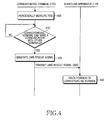
- FIG. 4 is a flow diagram illustrating a process for transmitting the UWB signals from the corresponding terminal to the searching apparatus according to an embodiment of the present invention.
- the corresponding terminal 100 periodically measures a RSSI through the received signal strength measurement unit 270 in step 400. Then, the corresponding terminal 100 determines whether the corresponding terminal 100 can communicate with other terminals in step 410.
- the criteria for determining whether the corresponding terminal 100 can communicate with other terminals are as follows.
- the corresponding terminal 100 periodically measures the RSSI and determines whether the measured RSSI is smaller than the reference RSSI representing the occurrence of an emergency.
- the corresponding terminal 100 shifts to an emergency rescue mode.
- the reference RSSI may be determined in advance through negotiation with the carrier, or mobile communication service provider.
- the corresponding terminal 100 when a RSSI, which represents that the corresponding terminal 100 cannot make a communication with other terminals due to an emergency, is measured, the corresponding terminal 100 generates and transmits the UWB signals in step 420. Then, the searching apparatus 110 detects the UWB signals and tracks the victim's exact position in step 440 by tracking the position of the mobile terminal 100.
- the searching apparatus receives the automatically transmitted UWB signals, calculates the exact point, and displays the calculated point on a screen, thereby allowing a rescue team to find out the victim's position.
- the rescue center or a searching apparatus can remotely transmit a control message allowing UWB signals to be transmitted from a corresponding terminal in an alternative embodiment of the present invention.
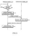
- FIG. 5 is a flow diagram illustrating a UWB signal request process of the searching apparatus
- FIG. 6 is a diagram illustrating a format structure of a control message
- FIG. 7 is a diagram illustrating the construction example of a data type in the format of the control message of FIG. 6.
- the rescue center registers information for a corresponding terminal to be urgently tracked.
- the report is a report for requesting an emergency tracking for the corresponding terminal located at a place at which the emergency has occurred.
- the report may be generated by a rescue request of a victim carrying the corresponding terminal, the family who desire to find the victim, or persons around the place at which the emergency has occurred.
- the information for the corresponding terminal includes the phone number and general position information of the corresponding terminal. Accordingly, the rescue center can send a rescue team to the general position at which the emergency has occurred.
- the rescue team receives the UWB signals through the searching apparatus to find the victim's exact position.
- the searching apparatus includes a function for controlling the UWB signals transmitted from the corresponding terminal.
- the rescue center may also control the UWB signals when the rescue center accepts the report. Such control is effected by transmission of a predetermined control message to the corresponding terminal.
- the rescue team transmits the control message to the corresponding terminal 100 through the searching apparatus 110.
- the searching apparatus 110 determines whether key input for performing an emergency tracking is received from the rescue team in step 500.
- the searching apparatus 110 generates an emergency tracking request message, which is a control message including control contents for an emergency rescue mode of the corresponding terminal 100, in step 510.
- the generated emergency tracking request message is transmitted to the corresponding terminal 100.
- the corresponding terminal 100 shifts to the emergency rescue mode. Then, the corresponding terminal 100 analyzes the emergency tracking request message and generates UWB signals according to the analysis result in step 530. The process of generating the UWB signals occurs as described above. The corresponding terminal 100 transmits the generated UWB signals to the searching apparatus 110 in step 540. Accordingly, the searching apparatus 110 starts to track the exact position of the corresponding terminal 100 in step 550.
- the tracking of the exact position is performed by means of an algorithm according to an embodiment of the present invention.
- the emergency tracking request message is the control message which includes the control contents for the emergency rescue mode of the corresponding terminal 100 and controls the UWB signals to be transmitted from the corresponding terminal 100.
- the emergency tracking request message may be transmitted by means of a Short Message Service (SMS).
- SMS Short Message Service
- a message format is determined in advance, which represents that the emergency tracking request message is a message allowing transmission of the UWB signals, between the rescue center or the searching apparatus 110 and the corresponding terminal 100.
- the emergency tracking request message has a typical short message format as shown in FIG. 6.
- One frame of the short message includes a message ID field for identification of the message, a priority field representing the priority of the short message, a privacy field, user data field and various fields necessary for transmission/reception of the short message.
- the user data field is a field representing actual data transmitted from a caller to a receiver in a general short message.
- predetermined upper bytes are used for representing that the emergency tracking request message is a message allowing transmission of the UWB signals.
- a "DATA TYPE” field of the "USER DATA” field designates a data type and represents the type of transmitted data as shown in FIG. 7.
- the "DATA TYPE” field includes specific codes according to the type of transmitted data. From among these codes, data representing the emergency tracking request message is defined in number portions reserved for future use, which have hexa values of 21-6F, A0-BF and E0-FF. Accordingly, when the above hexa values are recorded in the first byte of the "USER DATA” field, it can be understood that the data recorded in the "DATA TYPE” field is the emergency tracking request message.
- TP-UDHI TP-User Data Header Indicator
- TP-UDH Transfer layer Protocol-Use Data Header
- specific attribute is assigned to the user data of the short message by means of the TP-UDH.
- the structure of the TP-UDH defined in the 3GPP TS 23.040 includes an Information Element Identifier (IEI) and an Information Element Data (IED).
- a new IEI for UWB is defined in number portions reserved for future use. Accordingly, the searching apparatus allows the corresponding terminal to determine whether a corresponding IEI is included in the header of a received emergency tracking request message. When the corresponding IEI is included in the header, the searching apparatus forcedly operates a function in which the corresponding terminal recognizes that the received message is the emergency tracking request message and transmits the UWB signals.
- a Tx output value is required to have a value of ⁇ 50 dBm.
- the IEI denotes 'UWB Requested Transmission Power' and the IED denotes 'Requested Transmission Power (-dBm)'.
- the rescue team can perform the searching operations by gradually increasing the output power of the searching apparatus.
- the emergency tracking request message includes a predetermined code representing that the emergency tracking request message is a control message for controlling the UWB signals to be transmitted from the corresponding terminal 100.
- the emergency tracking request message includes a predetermined code value for controlling an output value at which the UWB signals are outputted. Accordingly, the corresponding terminal 100 may determine the output value of the UWB signals according to the predetermined code value for controlling the output value at which the UWB signals are outputted.
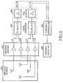
- the searching apparatus denotes an apparatus for searching the position of the corresponding terminal transmitting the UWB signals and has the construction as shown in FIG. 8, which is a block diagram schematically illustrating the construction of the searching apparatus.
- the searching apparatus includes a UWB signal receiver 800 having four antennas for receiving UWB signals, a UWB signal amplifier 810 for amplifying received UWB signals, a cross-correlator 820 for cross-correlating received signals, a peak detector 830, a coordinate operation unit 840 and a coordinate display unit 850.
- the peak detector 830 detects a peak value outputted from the cross-correlator 820 and calculates time difference between two received signals correlated to each other.
- the coordinate operation unit 840 calculates a position coordinate of a victim by means of the time difference calculated by the peak detector 830.
- the coordinate display unit 850 displays a final position coordinate.
- FIG. 9 is a diagram illustrating the screen of the searching apparatus for displaying the position of the corresponding terminal 100 according to an embodiment of the present invention.
- relative distance between the corresponding terminal 100 and the searching apparatus is displayed on the coordinate display unit 850 through a number 710.
- the direction of the corresponding terminal 100 with respect to the searching apparatus is displayed on the coordinate display unit 850 by a needle 700pointing in the direction of the corresponding terminal 100.
- the searching apparatus uses a TDOA scheme as a positioning method for receiving UWB signals and calculating the position of the corresponding terminal.
- TDOA scheme a positioning method for receiving UWB signals and calculating the position of the corresponding terminal.
- antennas are restrictively disposed as shown in FIG. 10. That is, four antennas are determined to be disposed at positions L, R, F and B. Further, the four antennas are disposed in such a manner that the four antennas form a lozenge having diagonal lines with lengths of 2L and 2K and the coordinates of each antenna are R(K, 0), L(-K, 0), F(0, L) and B(0, -L) with respect to the origin.
- a hyperbola which has focuses located at the antennas R and L and includes dots having a constant difference of 2 ⁇ between distances from each dot to the two focuses, is expressed by Equation (1) below.
- a hyperbola which has focuses located at the antennas F and B and includes dots having a constant difference 2 ⁇ between distances from each dot to the two focuses, is expressed by Equation (2) below.
- y ⁇ b ⁇ ( a 2 + ⁇ 2 ) ( ⁇ 2 b 2 - ⁇ 2 ⁇ 2 )
- the ⁇ has a value of T L -T R and the ⁇ value denotes a value obtained by subtracting the T R , which is a time at which a signal reaches the antenna R, from the T L which is a time at which a signal reaches the antenna L.
- the ⁇ has a value of T B- T F and the ⁇ value denotes a value obtained by subtracting the T F which is a time at which a signal reaches the antenna F, from the T B which is a time at which a signal reaches the antenna B.
- Equation (3) it is possible to determine a direction, that is, a quadrant in which the corresponding terminal is actually located.
- the quadrant in which the corresponding terminal is located is determined by pseudo code shown in Table 1.
- Table 1 represents a pseudo code for selecting the quadrant in which the corresponding terminal is located. Table 1 If ⁇ > 0 and ⁇ > 0 then exists in FIRST quadrant else if ⁇ ⁇ 0 and ⁇ > 0 then exists in SECOND quadrant else if ⁇ ⁇ 0 and ⁇ ⁇ 0 then exists in THIRD quadrant else if ⁇ > 0 and ⁇ ⁇ 0 then exists in FOURTH quadrant end
- the inputted UWB signals are amplified by the UWB signal amplifier 810 connected to the UWB signal receiver 800.
- signals r 1 (t), r 2 (t), r 3 (t) and r 4 (t) are outputted.
- the signals r 1 (t), r 2 (t), r 3 (t) and r 4 (t) are cross-correlated by the cross-correlator 820 and outputted to the peak detector 830.
- the peak detector 830 calculates a time difference of arrival (i.e.,
- the coordinate operation unit 840 receives the
- Equation (4) The orthogonal coordinate of the corresponding terminal 100 calculated through the aforementioned method is expressed by Equation (4).
- the R in Equation (4) denotes distance from a central point of the antennas.
- a polar coordinate for the corresponding terminal 100 is calculated through Equation (5) and expressed by a straight line connecting the antenna L to the antenna R and an angle ⁇ between the antenna L and the antenna R. Accordingly, the distance R and the angle ⁇ calculated through the aforementioned method are displayed on the coordinate display unit 850 through the distance 710 and the direction 700 of an arrow as shown in FIG. 9.
- the following Equations (4) and (5) are equations for indicating distance and direction between the searching apparatus and the corresponding terminal as relative distance and direction from the origin.
- the present invention in relation to a method for tracking a corresponding terminal, it is possible to easily find out the position of the corresponding terminal transmitting UWB signals through an algorithm which is a simply standardized equation. Further, a position tracking is performed through a small searching apparatus instead of a base station, so that a rescue team can perform rescue operations with the searching apparatus. Therefore, it is possible to perform more quick and effective rescue operations. That is, when the present invention is complementarily used with a GPS illustrating a relatively macroscopic position, it is possible to quickly find out the exact position of the corresponding terminal.
- a UWB receiver is miniaturized and the time-resolution in a cross-correlator increases due to the development of MEMS technology, so that a searching apparatus can be mounted on a mobile communication terminal. Therefore, the present invention can be used in not only rescue operations but also various location-based services such as searching for a missing child and searching for a car in a parking place.
Applications Claiming Priority (1)
| Application Number | Priority Date | Filing Date | Title |
|---|---|---|---|
| KR1020040068389A KR100663530B1 (ko) | 2004-08-30 | 2004-08-30 | UWB(Ultra-Wideband) 신호를 이용한 긴급구조 신호 송/수신 장치 및 그 방법 |
Publications (1)
| Publication Number | Publication Date |
|---|---|
| EP1630966A1 true EP1630966A1 (fr) | 2006-03-01 |
Family
ID=36139689
Family Applications (1)
| Application Number | Title | Priority Date | Filing Date |
|---|---|---|---|
| EP05015812A Withdrawn EP1630966A1 (fr) | 2004-08-30 | 2005-07-20 | Dispositif et procédé de transmission/réception de requêtes de sauvetage d'urgence par utilisation de signaux à bande ultra large |
Country Status (4)
| Country | Link |
|---|---|
| US (1) | US7570938B2 (fr) |
| EP (1) | EP1630966A1 (fr) |
| KR (1) | KR100663530B1 (fr) |
| CN (1) | CN100418307C (fr) |
Cited By (3)
| Publication number | Priority date | Publication date | Assignee | Title |
|---|---|---|---|---|
| DE102006038856A1 (de) * | 2006-08-20 | 2008-02-21 | Symeo Gmbh | Vorrichtung und Verfahren zur Positions- und/oder Geschwindigkeitsbestimmung, insbesondere unter Einsatz von Absolutlaufzeiten und Laufzeitunterschieden von Signalen |
| WO2008117253A1 (fr) * | 2007-03-27 | 2008-10-02 | Saulle Mattei | Dispositif d'alerte et procédé permettant de localiser et communiquer un signal de détresse à un personnel de sécurité |
| EP2367021A1 (fr) | 2010-03-17 | 2011-09-21 | The Swatch Group Research and Development Ltd. | Procédé et système de localisation d'objets |
Families Citing this family (17)
| Publication number | Priority date | Publication date | Assignee | Title |
|---|---|---|---|---|
| US20070219420A1 (en) * | 2006-03-17 | 2007-09-20 | Moore Barrett H | Subscription-Based Catastrophe-Triggered Rescue Services Facilitation Method Using Wireless Location Information |
| US8920343B2 (en) | 2006-03-23 | 2014-12-30 | Michael Edward Sabatino | Apparatus for acquiring and processing of physiological auditory signals |
| KR100771466B1 (ko) * | 2006-04-27 | 2007-10-30 | 김정선 | 재난 구조용 GPS주파수가 130 dBm 펄스 폭에 형성된5 ㎓ 밀리미터파 주파수대역을 이용한 초 광대역주파수확장변조 복합무선통신시스템 |
| US7839290B2 (en) * | 2006-11-01 | 2010-11-23 | David Welford Chidakel | Sonic building rescue beacon |
| JP4601684B2 (ja) * | 2008-04-25 | 2010-12-22 | シャープ株式会社 | 避難経路取得システム、携帯端末装置、避難経路取得方法、避難経路取得プログラム、コンピュータ読み取り可能な記録媒体 |
| JP4536790B2 (ja) * | 2008-04-30 | 2010-09-01 | シャープ株式会社 | 情報出力装置、情報出力方法、制御プログラム、コンピュータ読み取り可能な記録媒体、および電子会議システム |
| US8483720B2 (en) * | 2008-06-11 | 2013-07-09 | Freescale Semiconductor, Inc. | Smart/active RFID tag for use in a WPAN |
| US8116350B1 (en) | 2009-01-14 | 2012-02-14 | The United States Of America As Represented By The Administrator Of The National Aeronautics And Space Administration | Ultrawideband asynchronous tracking system and method |
| US8457148B2 (en) * | 2009-03-12 | 2013-06-04 | Lockheed Martin Corporation | Method for maintaining vital guideway operation in high-demand areas |
| US20120202523A1 (en) * | 2009-07-10 | 2012-08-09 | Nec Europe Ltd. | System and a method for employing swarms of electronic devices to locate survivors in the event of catastrophic structure collapse |
| US9332119B1 (en) * | 2013-03-07 | 2016-05-03 | Serdar Artun Danis | Systems and methods for call destination authenticaiton and call forwarding detection |
| US10454602B2 (en) * | 2015-01-06 | 2019-10-22 | Lg Electronics Inc. | Apparatus for transmitting broadcast signals, apparatus for receiving broadcast signals, method for transmitting broadcast signals and method for receiving broadcast signals |
| KR101786225B1 (ko) * | 2015-11-26 | 2017-10-18 | (주)아이엠티(Imt) | 비콘발생기를 이용한 화재용 구조장치를 이용한 구조방법 |
| CN107991648B (zh) * | 2017-11-28 | 2019-10-11 | 中国联合网络通信集团有限公司 | 一种受灾人员的搜救定位方法及装置 |
| CN109581288B (zh) * | 2018-11-16 | 2021-01-12 | 广州杰赛科技股份有限公司 | 室内定位方法、设备及存储介质 |
| KR102180836B1 (ko) * | 2019-12-27 | 2020-11-20 | 동국대학교 산학협력단 | 조난자 단말 장치로부터 근거리 통신 모듈을 통해 조난 신호를 수신하는 구조대 단말 장치 및 그 동작 방법 |
| CN113225686B (zh) * | 2021-03-30 | 2023-01-10 | 中铁二院工程集团有限责任公司 | 一种室内环境基于uwb的智能呼叫的系统和方法 |
Citations (4)
| Publication number | Priority date | Publication date | Assignee | Title |
|---|---|---|---|---|
| US20010036832A1 (en) * | 2000-04-14 | 2001-11-01 | Onscene, Inc. | Emergency command and control system |
| US20030069025A1 (en) * | 2001-10-09 | 2003-04-10 | General Electric Company | Transmitter location for ultra-wideband, transmitted-reference CDMA communication system |
| US20030197643A1 (en) * | 1998-03-23 | 2003-10-23 | Fullerton Larry W. | System and method for position determination by impulse radio |
| US20040002346A1 (en) * | 2000-12-14 | 2004-01-01 | John Santhoff | Ultra-wideband geographic location system and method |
Family Cites Families (13)
| Publication number | Priority date | Publication date | Assignee | Title |
|---|---|---|---|---|
| US5748147A (en) * | 1992-03-04 | 1998-05-05 | Motorola Inc | Position locating rescue transceiver |
| KR100449616B1 (ko) * | 2000-06-30 | 2004-09-22 | 엔티티 도꼬모 인코퍼레이티드 | 위치정보 서비스를 지원하기 위한 방법 및 장치 |
| US6519464B1 (en) * | 2000-12-14 | 2003-02-11 | Pulse-Link, Inc. | Use of third party ultra wideband devices to establish geo-positional data |
| JP2002277539A (ja) | 2001-03-21 | 2002-09-25 | Tateyama Kagaku Kogyo Kk | 山岳遭難者探査システム |
| US7224955B2 (en) * | 2001-05-18 | 2007-05-29 | Lg Electronics, Inc. | Apparatus and method for sending emergency rescue signal using mobile communication terminal |
| KR100547824B1 (ko) * | 2001-12-29 | 2006-02-01 | 삼성전자주식회사 | 블루투스를 구비하는 이동통신 단말기에서 긴급구조요청방법 |
| EP1477950B1 (fr) * | 2002-02-18 | 2006-12-20 | Fujitsu Limited | Procede pour la securite |
| KR100519845B1 (ko) * | 2002-10-15 | 2005-10-06 | 주식회사 팬택 | 이동통신 단말기를 이용한 긴급상황 통보 장치 |
| JP2004221926A (ja) | 2003-01-15 | 2004-08-05 | Miyata Tadanori | 救護システム |
| JP3934065B2 (ja) * | 2003-01-24 | 2007-06-20 | 松下電器産業株式会社 | 緊急通報端末装置およびシステム |
| TW200424548A (en) * | 2003-05-14 | 2004-11-16 | Leadtek Research Inc | GPS having an emergency call function |
| KR20050081556A (ko) * | 2004-02-14 | 2005-08-19 | 삼성전자주식회사 | 초광대역 통신방법 및 장치 |
| KR100842548B1 (ko) * | 2004-03-05 | 2008-07-01 | 삼성전자주식회사 | 긴급 호출 시스템 및 그 제어 방법 |
-
2004
- 2004-08-30 KR KR1020040068389A patent/KR100663530B1/ko active IP Right Grant
-
2005
- 2005-05-19 US US11/133,041 patent/US7570938B2/en active Active
- 2005-06-29 CN CNB2005100823048A patent/CN100418307C/zh not_active Expired - Fee Related
- 2005-07-20 EP EP05015812A patent/EP1630966A1/fr not_active Withdrawn
Patent Citations (4)
| Publication number | Priority date | Publication date | Assignee | Title |
|---|---|---|---|---|
| US20030197643A1 (en) * | 1998-03-23 | 2003-10-23 | Fullerton Larry W. | System and method for position determination by impulse radio |
| US20010036832A1 (en) * | 2000-04-14 | 2001-11-01 | Onscene, Inc. | Emergency command and control system |
| US20040002346A1 (en) * | 2000-12-14 | 2004-01-01 | John Santhoff | Ultra-wideband geographic location system and method |
| US20030069025A1 (en) * | 2001-10-09 | 2003-04-10 | General Electric Company | Transmitter location for ultra-wideband, transmitted-reference CDMA communication system |
Cited By (5)
| Publication number | Priority date | Publication date | Assignee | Title |
|---|---|---|---|---|
| DE102006038856A1 (de) * | 2006-08-20 | 2008-02-21 | Symeo Gmbh | Vorrichtung und Verfahren zur Positions- und/oder Geschwindigkeitsbestimmung, insbesondere unter Einsatz von Absolutlaufzeiten und Laufzeitunterschieden von Signalen |
| WO2008117253A1 (fr) * | 2007-03-27 | 2008-10-02 | Saulle Mattei | Dispositif d'alerte et procédé permettant de localiser et communiquer un signal de détresse à un personnel de sécurité |
| EP2367021A1 (fr) | 2010-03-17 | 2011-09-21 | The Swatch Group Research and Development Ltd. | Procédé et système de localisation d'objets |
| EP2367022A1 (fr) | 2010-03-17 | 2011-09-21 | The Swatch Group Research and Development Ltd. | Procédé et système de localisation d'objets |
| US8624774B2 (en) | 2010-03-17 | 2014-01-07 | The Swatch Group Research And Development Ltd | Method and system of locating objects |
Also Published As
| Publication number | Publication date |
|---|---|
| CN1744446A (zh) | 2006-03-08 |
| KR20060019744A (ko) | 2006-03-06 |
| CN100418307C (zh) | 2008-09-10 |
| US20060046687A1 (en) | 2006-03-02 |
| KR100663530B1 (ko) | 2007-01-02 |
| US7570938B2 (en) | 2009-08-04 |
Similar Documents
| Publication | Publication Date | Title |
|---|---|---|
| US7570938B2 (en) | Apparatus and method for transmitting/receiving an emergency rescue request using UWB signals | |
| EP3091366B1 (fr) | Système et procédé de localisation de dispositifs mobiles dans des environnements confinés | |
| US7366492B1 (en) | Method and system for mobile location detection using handoff information | |
| US10568062B2 (en) | Positioning for WLANs and other wireless networks | |
| Wang et al. | Location based services for mobiles: Technologies and standards | |
| US6421009B2 (en) | Mobile station position tracking system for public safety | |
| US6677895B1 (en) | System and method for determining the location of a transmitting mobile unit | |
| EP1527651B1 (fr) | Systeme de localisation d'une unite mobile | |
| JP3694023B2 (ja) | アナログセルラシステムで使用するための位置決定方法 | |
| US7050786B2 (en) | Method and apparatus for locating a wireless device | |
| US6839022B1 (en) | Network support for subscriber access to mobile caller location information | |
| US7667648B2 (en) | Facilitating mobile station location using a ground-based cellular network | |
| KR20010041081A (ko) | 위치확인 비콘 시스템 | |
| US8081923B1 (en) | Method and apparatus for providing location services for a distributed network | |
| JPH11275642A (ja) | 移動通信装置の位置判定方法、機器および移動通信装置 | |
| US20080153509A1 (en) | Method for locating a mobile communication device | |
| Bull | Wireless geolocation | |
| WO2017101880A1 (fr) | Procédé et système de localisation en intérieur dans une zone de couverture importante | |
| JP4734242B2 (ja) | 推定と経験則に基づく信号強度測定値のパターンマッチングによる無線端末の位置特定方法 | |
| KR100658573B1 (ko) | 이동통신 단말 기반 위치측위 및 위치정보 획득 방법 | |
| JPH08179028A (ja) | セルラー電話における移動局の現在位置検出サービス方式 | |
| KR100421956B1 (ko) | 이동통신 시스템을 이용한 휴대단말기 측위방법 | |
| KR101128841B1 (ko) | 이동통신 시스템에서 채널 변경을 이용하여 재해 경보를알리는 방법 및 시스템 | |
| CN117939010A (en) | Mobile phone positioning system based on signal emission |
Legal Events
| Date | Code | Title | Description |
|---|---|---|---|
| PUAI | Public reference made under article 153(3) epc to a published international application that has entered the european phase |
Free format text: ORIGINAL CODE: 0009012 |
|
| 17P | Request for examination filed |
Effective date: 20050720 |
|
| AK | Designated contracting states |
Kind code of ref document: A1 Designated state(s): AT BE BG CH CY CZ DE DK EE ES FI FR GB GR HU IE IS IT LI LT LU LV MC NL PL PT RO SE SI SK TR |
|
| AX | Request for extension of the european patent |
Extension state: AL BA HR MK YU |
|
| 17Q | First examination report despatched |
Effective date: 20060726 |
|
| AKX | Designation fees paid |
Designated state(s): DE FR GB |
|
| 17Q | First examination report despatched |
Effective date: 20060726 |
|
| STAA | Information on the status of an ep patent application or granted ep patent |
Free format text: STATUS: THE APPLICATION IS DEEMED TO BE WITHDRAWN |
|
| 18D | Application deemed to be withdrawn |
Effective date: 20101019 |