EP1627768A2 - Klappbarer Sitz, insbesondere für ein Kraftfahrzeug - Google Patents
Klappbarer Sitz, insbesondere für ein Kraftfahrzeug Download PDFInfo
- Publication number
- EP1627768A2 EP1627768A2 EP05025304A EP05025304A EP1627768A2 EP 1627768 A2 EP1627768 A2 EP 1627768A2 EP 05025304 A EP05025304 A EP 05025304A EP 05025304 A EP05025304 A EP 05025304A EP 1627768 A2 EP1627768 A2 EP 1627768A2
- Authority
- EP
- European Patent Office
- Prior art keywords
- seat
- backrest
- seat part
- loading area
- lever
- Prior art date
- Legal status (The legal status is an assumption and is not a legal conclusion. Google has not performed a legal analysis and makes no representation as to the accuracy of the status listed.)
- Granted
Links
Images


Classifications
-
- B—PERFORMING OPERATIONS; TRANSPORTING
- B60—VEHICLES IN GENERAL
- B60N—SEATS SPECIALLY ADAPTED FOR VEHICLES; VEHICLE PASSENGER ACCOMMODATION NOT OTHERWISE PROVIDED FOR
- B60N2/00—Seats specially adapted for vehicles; Arrangement or mounting of seats in vehicles
- B60N2/24—Seats specially adapted for vehicles; Arrangement or mounting of seats in vehicles for particular purposes or particular vehicles
- B60N2/30—Non-dismountable or dismountable seats storable in a non-use position, e.g. foldable spare seats
- B60N2/3072—Non-dismountable or dismountable seats storable in a non-use position, e.g. foldable spare seats on a lower level of a multi-level vehicle floor
-
- B—PERFORMING OPERATIONS; TRANSPORTING
- B60—VEHICLES IN GENERAL
- B60N—SEATS SPECIALLY ADAPTED FOR VEHICLES; VEHICLE PASSENGER ACCOMMODATION NOT OTHERWISE PROVIDED FOR
- B60N2/00—Seats specially adapted for vehicles; Arrangement or mounting of seats in vehicles
- B60N2/24—Seats specially adapted for vehicles; Arrangement or mounting of seats in vehicles for particular purposes or particular vehicles
- B60N2/30—Non-dismountable or dismountable seats storable in a non-use position, e.g. foldable spare seats
- B60N2/3002—Non-dismountable or dismountable seats storable in a non-use position, e.g. foldable spare seats back-rest movements
- B60N2/3004—Non-dismountable or dismountable seats storable in a non-use position, e.g. foldable spare seats back-rest movements by rotation only
- B60N2/3009—Non-dismountable or dismountable seats storable in a non-use position, e.g. foldable spare seats back-rest movements by rotation only about transversal axis
- B60N2/3013—Non-dismountable or dismountable seats storable in a non-use position, e.g. foldable spare seats back-rest movements by rotation only about transversal axis the back-rest being hinged on the vehicle frame
-
- B—PERFORMING OPERATIONS; TRANSPORTING
- B60—VEHICLES IN GENERAL
- B60N—SEATS SPECIALLY ADAPTED FOR VEHICLES; VEHICLE PASSENGER ACCOMMODATION NOT OTHERWISE PROVIDED FOR
- B60N2/00—Seats specially adapted for vehicles; Arrangement or mounting of seats in vehicles
- B60N2/24—Seats specially adapted for vehicles; Arrangement or mounting of seats in vehicles for particular purposes or particular vehicles
- B60N2/30—Non-dismountable or dismountable seats storable in a non-use position, e.g. foldable spare seats
- B60N2/3002—Non-dismountable or dismountable seats storable in a non-use position, e.g. foldable spare seats back-rest movements
- B60N2/3029—Non-dismountable or dismountable seats storable in a non-use position, e.g. foldable spare seats back-rest movements by composed movement
- B60N2/3031—Non-dismountable or dismountable seats storable in a non-use position, e.g. foldable spare seats back-rest movements by composed movement in a longitudinal-vertical plane
-
- B—PERFORMING OPERATIONS; TRANSPORTING
- B60—VEHICLES IN GENERAL
- B60N—SEATS SPECIALLY ADAPTED FOR VEHICLES; VEHICLE PASSENGER ACCOMMODATION NOT OTHERWISE PROVIDED FOR
- B60N2/00—Seats specially adapted for vehicles; Arrangement or mounting of seats in vehicles
- B60N2/24—Seats specially adapted for vehicles; Arrangement or mounting of seats in vehicles for particular purposes or particular vehicles
- B60N2/30—Non-dismountable or dismountable seats storable in a non-use position, e.g. foldable spare seats
- B60N2/3038—Cushion movements
- B60N2/3063—Cushion movements by composed movement
- B60N2/3065—Cushion movements by composed movement in a longitudinal-vertical plane
-
- B—PERFORMING OPERATIONS; TRANSPORTING
- B60—VEHICLES IN GENERAL
- B60N—SEATS SPECIALLY ADAPTED FOR VEHICLES; VEHICLE PASSENGER ACCOMMODATION NOT OTHERWISE PROVIDED FOR
- B60N2/00—Seats specially adapted for vehicles; Arrangement or mounting of seats in vehicles
- B60N2/24—Seats specially adapted for vehicles; Arrangement or mounting of seats in vehicles for particular purposes or particular vehicles
- B60N2/30—Non-dismountable or dismountable seats storable in a non-use position, e.g. foldable spare seats
- B60N2/3088—Non-dismountable or dismountable seats storable in a non-use position, e.g. foldable spare seats characterised by the mechanical link
- B60N2/309—Non-dismountable or dismountable seats storable in a non-use position, e.g. foldable spare seats characterised by the mechanical link rods
-
- B—PERFORMING OPERATIONS; TRANSPORTING
- B60—VEHICLES IN GENERAL
- B60N—SEATS SPECIALLY ADAPTED FOR VEHICLES; VEHICLE PASSENGER ACCOMMODATION NOT OTHERWISE PROVIDED FOR
- B60N2/00—Seats specially adapted for vehicles; Arrangement or mounting of seats in vehicles
- B60N2/24—Seats specially adapted for vehicles; Arrangement or mounting of seats in vehicles for particular purposes or particular vehicles
- B60N2/30—Non-dismountable or dismountable seats storable in a non-use position, e.g. foldable spare seats
- B60N2/3088—Non-dismountable or dismountable seats storable in a non-use position, e.g. foldable spare seats characterised by the mechanical link
- B60N2/3093—Non-dismountable or dismountable seats storable in a non-use position, e.g. foldable spare seats characterised by the mechanical link slides
-
- B—PERFORMING OPERATIONS; TRANSPORTING
- B60—VEHICLES IN GENERAL
- B60N—SEATS SPECIALLY ADAPTED FOR VEHICLES; VEHICLE PASSENGER ACCOMMODATION NOT OTHERWISE PROVIDED FOR
- B60N2/00—Seats specially adapted for vehicles; Arrangement or mounting of seats in vehicles
- B60N2/24—Seats specially adapted for vehicles; Arrangement or mounting of seats in vehicles for particular purposes or particular vehicles
- B60N2/32—Seats specially adapted for vehicles; Arrangement or mounting of seats in vehicles for particular purposes or particular vehicles convertible for other use
- B60N2/36—Seats specially adapted for vehicles; Arrangement or mounting of seats in vehicles for particular purposes or particular vehicles convertible for other use into a loading platform
Definitions
- the invention relates to a folding seat, in particular for a motor vehicle, according to the preamble of claim 1.
- US 5,527,087 A shows a folding seat, wherein the backrest is connected via a rotation axis fixed to a body of a motor vehicle.
- a rear end of a seat portion is pivotally connected to a lower end of the seat back via an axis of rotation.
- a front portion of the seat portion is at least one pivotable lever from a position for a seat function in a position for a loading area function and back adjustable. In the loading area function, a back of the backrest serves as a loading area.
- a vehicle seat in which a backrest is hinged so that it can be folded from a locked normal sitting position forward on a seat part and in this position also locked.
- a backrest support is attached to both sides, on which the backrest is articulated pivotably about a pivot axis.
- the object of the invention is to provide a folding seat, in particular for a motor vehicle, which has a simple structure.
- the seat according to the invention has an advantageous construction, which consists in principle in that the backrest of the seat is connected via a pivot or rotation axis fixed to a vehicle body or the backrest carriers, which are located on both sides of the seat part.
- the seat part or Seat cushion is in turn rotatably connected at its rear end to a lower end of the backrest.
- the backrest supports for the backrest are not mounted to the vehicle body but are located on one seat rail each.
- the kinematics of the hinged at the front end of the seat part lever can be designed so that the connection to a front end of the seat part remains fixed to the body.
- a front end of the seat part is displaceable and / or pivotally connected to the body via at least one rotatably mounted lever.
- the kinematics of the seat part can be designed so that the lever in its end position, in which the backrest is folded forward, are in the extended position and it comes to a locking of the seat via a toggle effect. Due to this kinematics according to the invention results in the folding of the backrest forward, after a corresponding unlocking the backrest, a very compact folding, whereby a favorable stowage of the seat, for example in the vehicle, is possible.
- the front end of the seat part is connected via a slotted guide with the body.
- the guided in the slotted guide pins engage in an advantageous embodiment in the end positions in a recess.
- the kinematics is designed so that the hinged at the front end of the seat part levers are positioned at a central seat height of the seat part perpendicular to the seat rail. With this kinematics, the seat part lowers when the backrest is pushed forward. In this position advantageously have smaller people and children the ability to conveniently park the feet in the footwell. In the other case, when the backrest is moved backwards over the seat rail, the seat part lowers again. In this sitting position, the legs of the person sitting on the seat can be comfortably stretched out.
- levers at the front end of the seat part are pivotable about the zero point forward and backward
- levers on the front End of the seat part from a front, lower position to a maximum position in a middle position or zero position or from a rear, lower position are pivotally maximum to the middle position.
- the lever is tilted obliquely backwards in its middle position, then the seat part lifts up to the foremost approachable position in the seat adjustment field. Since the rear end of the seat part is articulated firmly on the backrest support and thus is not adjusted in height with a constant backrest inclination, the front end of the seat part is raised when the seat is moved to a forward position. As a result, the position of the seat part is advantageously adapted to the steeper thigh angle of the person sitting on the seat. If, in this embodiment, the seat or the backrest is displaced into a rear position, the angle of the seat part becomes flatter again, as is advantageously the case with an extended thigh.
- the backrest is designed in an advantageous embodiment adjustable in its inclination.
- the kinematics is advantageously designed so that when a pivoting of the backrest to the rear, the seat cushion is flat. If the seat moved forward and the backrest pivoted to a more vertical position, the front end of the seat part occupies a higher position, while the rear end of the seat part is lowered by the erection of the backrest down. This results in a body-appropriate seat adjustment.
- a favorable folding is achieved by moving and pivoting the backrest to the front, which releases a relatively large amount of space for entry into a row of seats located behind the seat or a seat or a luggage compartment.
- the seat can advantageously be pivoted from the entry position into a loading position.
- the backrest is unlocked manually or automatically from the seat part.
- the backrest is pivoted forward and simultaneously pushed backwards due to the toggle effect.
- the hinged at the front end of the seat part lever is moved from an oblique position in an approximately horizontal position.
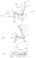
- Fig. 1 shows a first embodiment of a seat 1, which consists essentially of a seat part or seat cushion 2 and a backrest 3, in which a headrest 4 can be arranged or integrated.
- the backrest 3 has at its lower end 5 a rotary or pivot axis 6.
- the axis of rotation 6 is, in the case of application in a vehicle, arranged on a body 7. Spaced to the axis of rotation 6 for the backrest 3, a further rotary or pivot axis 8 is formed on which a dashed rear end 9 of the seat part 2 is articulated. Between a front end 10 of the seat part 2 and the rear end 9, the seat part 2 is guided in a slotted guide 11.
- the slotted guide 11 consists of a respective pin or pin 12 which projects laterally beyond the seat part 2.
- the slide guide 11 has a first approximately horizontal portion 13 and a second obliquely downwardly and rearwardly extending portion 14, through which the respective pin 12 is guided.
- the first portion 13 consists of a groove or depression, which is formed for example in a side wall or a sill of a motor vehicle 17.
- the seat part 2 has been pulled over the rotary movement of the backrest 3 onto a floor 16 of the vehicle 17 (not shown). In this position L, the seat part 2 is also again in an approximately horizontal position, as shown in FIG. 1. In the folded state of the seat 1 is a back 18 of the backrest 3 as an extended cargo area of a luggage space 19th
- FIGS. 4 and 6 show a second embodiment of a seat 20.
- the same components with the same reference numerals as in FIGS. 1 to 3 are provided.
- the essential difference from the first embodiment of the seat 1 shown in FIGS. 1 to 3 is that at least one lever 21 is provided between the front end 10 and the rear end 9 of the seat part 2 in the seat 20 instead of a slotted guide 11.
- An upper end 22 of the lever 21 is articulated to a seat bottom 27 via an upper joint 28 and a lower end 23 of the lever 21 is pivoted via a lower joint 25 to the body 7 and to a floor 16 of the vehicle 17.
- the backrest 3 and the seat part 2 are in a position S in which a person can sit on the seat 20.
- the backrest 3 is pivoted forwardly about the axis of rotation 6 from the seat position S shown in FIG. 4.
- the seat part 2 is pivoted from the sitting position in FIG. 4 on the axis of rotation 8 in a circular motion downwards.
- the lever 21 moves from the position S shown in dashed lines in Fig. 4 in a circular movement about the lower bearing or hinge 25 to the rear.
- the backrest 3 is in the horizontal position L, in which the backrest 3 has the function of a cargo area.
- the seat part 2 also has a horizontal position 26.
- the upper end 22 of the lever 21 has been pivoted downward in a circular motion.
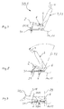
- FIGS. 7 to 17 show a third embodiment of a seat 30.
- the axis of rotation 6 is not fixedly attached to the body 7, but displaceable in a at the bottom 16 of the vehicle 17th fixed seat rail 31.
- FIGS. 7 to 9 the positions of the seat 30 according to FIGS. 1 to 3 and 4 to 6 for the seat 1 and the seat 20 are shown.
- the seat 30 is in the sitting position S.
- the same parts are denoted by the same reference numerals as in the preceding Figs.
- the backrest 3 is in a rearwardly inclined, oblique position 33, while the seat part 2 has an approximately horizontal position.
- the lever 21 is located in an obliquely inclined rearward position 32, which coincides approximately with the inclination of the backrest 3.
- Fig. 8 shows the pivoting of the backrest 3 forward. Due to the kinematics, the seat part 2 is pivoted downwards and backwards over the lever 21. At the same time, the backrest 3 shifts to the rear by a distance x.
- the backrest 3 is in the horizontal position L, in which the back 18 of the backrest 3 serves as a cargo area.
- the seat part 2 is also in a horizontal position.
- the backrest 3 is locked on the seat rail 31 in the rearmost position 29
- the seat part 2 is in contrast to the Fig. 7 in a front position 34. Accordingly, the lever 21 is pivoted to a front position 35.
- the slope of the backrest 3 remains unchanged in FIGS. 10 to 12.
- the lever 21 has been pivoted by an angle ⁇ to the rear in its middle position 36. At the same time the backrest 3 has been moved by a distance x to the rear on the seat rail 31 in the position 29.
- the lever 21 is in a rear position 24th
- Fig. 15 shows a position 40 of the backrest 3, in which the backrest 3 is pivoted in the embodiment shown a maximum of an angle ⁇ max to the rear. Accordingly, the rear end 9 has been adjusted maximally by an angle ⁇ max upwards.
- FIG. 16 shows the seat 30 in a position 41, in which the backrest 3 has been pushed forward on the seat rail 31 and at the same time has been pivoted forwards about the axis of rotation 6. In this position 41 is located behind the seat 30 row of seats or a luggage compartment easily accessible.
- FIG. 17 shows a so-called toggle effect, which automatically shifts the seat 30 to its rearmost position when the longitudinal adjustment is unlocked.
- a horizontal arrow 42 the displacement x of the lower end 5 of the backrest 3 is indicated to the rear.
- a vertical arrow 43 shows that the lever 21 pivots downward from its rearward position 39 into an approximately horizontal position 44 shown in FIG.
Landscapes
- Engineering & Computer Science (AREA)
- Aviation & Aerospace Engineering (AREA)
- Transportation (AREA)
- Mechanical Engineering (AREA)
- Seats For Vehicles (AREA)
Abstract
Description
- Die Erfindung betrifft einen klappbaren Sitz, insbesondere für ein Kraftfahrzeug, gemäß dem Oberbegriff des Anspruchs 1.
- Aus der US 5,527,087 A sind bereits die gattungbildenden Merkmale vorbekannt. Die US 5,527,087 A zeigt einen Faltsitz, bei dem die Rückenlehne über eine Drehachse fest mit einer Karosserie eines Kraftfahrzeuges verbunden ist. Ein hinteres Ende eines Sitzteils ist an einem unteren Ende der Rückenlehne über eine Drehachse verschwenkbar verbunden. Ein vorderer Bereich des Sitzteiles ist über mindestens einen verschwenkbaren Hebel aus einer Position für eine Sitzfunktion in eine Position für eine Ladeflächenfunktion und zurück verstellbar. In der Ladeflächenfunktion dient eine Rückseite der Rückenlehne als Ladefläche.
- Aus der EP 0 999 092 A2 ist bereits ein Fahrzeugsitz bekannt, bei dem eine Rückenlehne so angelenkt ist, dass diese aus einer verriegelten Normal-Sitzposition nach vorne auf ein Sitzteil klappbar und in dieser Position auch verriegelbar ist. An dem Sitzteil ist an beiden Seiten je ein Rückenlehnenträger angebracht, an dem die Rückenlehne um eine Schwenkachse schwenkbar angelenkt ist.
- Aufgabe der Erfindung ist es, einen klappbaren Sitz, insbesondere für ein Kraftfahrzeug, zu schaffen, der einen einfachen Aufbau aufweist.
- Diese Aufgabe wird durch die Merkmale des Anspruchs 1 gelöst.
- Der erfindungsgemäße Sitz weist einen vorteilhaften Aufbau auf, der im Prinzip darin besteht, dass die Rückenlehne des Sitzes über eine Schwenk- oder Drehachse fest mit einer Fahrzeugkarosserie oder den Rückenlehnenträgern verbunden ist, die sich an beiden Seiten des Sitzteiles befinden. Das Sitzteil oder Sitzkissen ist wiederum an seinem hinteren Ende drehbar mit einem unteren Ende der Rückenlehne verbunden. Die Rückenlehnenlager für die Rückenlehne sind nicht karosseriefest montiert, sondern befinden sich auf jeweils einer Sitzschiene. Bei diesem Aufbau kann die Kinematik der am vorderen Ende des Sitzteils angelenkten Hebel so ausgelegt werden, dass die Anbindung an einem vorderen Ende des Sitzteils weiterhin karosseriefest bleibt. Ein vorderes Ende des Sitzteiles ist über mindestens einen drehbar gelagerten Hebel verschiebbar und/oder verschwenkbar mit der Karosserie verbunden. Über die Hebellängen kann die Kinematik des Sitzteiles so ausgelegt werden, dass sich die Hebel in ihrer Endlage, in der die Rückenlehne nach vorne geklappt ist, in der Strecklage befinden und es dadurch zu einer Verriegelung des Sitzes über einen Kniehebeleffekt kommt. Aufgrund dieser erfindungsgemäßen Kinematik ergibt sich beim Klappen der Rückenlehne nach vorne, nach einer entsprechenden Entriegelung der Rückenlehne, eine sehr kompakte Faltung, wodurch eine günstige Verstauung des Sitzes, beispielsweise im Fahrzeug, ermöglicht wird.
- In einer alternativen Ausführungsform ist das vordere Ende des Sitzteils über eine Kulissenführung mit der Karosserie verbunden. Die in der Kulissenführung geführten Stifte rasten in einer vorteilhaften Ausführungsform in den Endlagen in eine Vertiefung ein.
- In einer vorteilhaften Ausführungsform ist die Kinematik so ausgelegt, dass die am vorderen Ende des Sitzteils angelenkten Hebel in einer mittleren Sitzhöhe des Sitzteiles rechtwinklig zur Sitzschiene positioniert sind. Bei dieser Kinematik senkt sich das Sitzteil, wenn die Rückenlehne nach vorne geschoben wird. In dieser Position haben vorteilhafterweise kleinere Personen und Kinder die Möglichkeit, die Füße im Fußraum bequem abzustellen. Im anderen Fall, wenn die Rückenlehne über die Sitzschiene nach hinten verfahren wird, senkt sich das Sitzteil wieder. In dieser Sitzposition können die Beine der auf dem Sitz befindlichen Person bequem ausgestreckt werden.
- Neben der vorhergehenden Ausführungsform, in der die Hebel am vorderen Ende des Sitzteiles über den Nullpunkt nach vorne und nach hinten verschwenkbar sind, gibt es weitere, vorteilhafte Ausführungsformen, bei denen die Hebel am vorderen Ende des Sitzteils aus einer vorderen, unteren Position maximal bis in eine mittlere Position oder Nullposition oder aus einer hinteren, unteren Position maximal bis in die mittlere Position verschwenkbar sind.
- Ist in einer vorteilhaften Ausführungsform der Hebel in seiner mittleren Position schräg nach hinten geneigt, so hebt sich das Sitzteil bis in die vorderste anfahrbare Position im Sitzverstellfeld an. Da das hintere Ende des Sitzteils fest am Lehnenträger angelenkt ist und somit bei einer gleichbleibenden Rückenlehnenneigung nicht höhenverstellt wird, wird das vordere Ende des Sitzteils angehoben, wenn der Sitz in eine weiter vorne liegende Position verschoben wird. Dadurch wird die Lage des Sitzteiles in vorteilhafter Weise dem steileren Oberschenkelwinkel der auf dem Sitz befindlichen Person anpaßt. Wird in dieser Ausführungsform der Sitz bzw. die Rückenlehne in eine hintere Position verschoben, so wird der Winkel des Sitzteils wieder flacher, wie dies vorteilhafterweise bei einem ausgestreckten Oberschenkel der Fall ist.
- Die Rückenlehne ist in einer vorteilhaften Ausführungsform in ihrer Neigung verstellbar ausgelegt.
- Die Kinematik ist vorteilhaftweise so ausgelegt, dass bei einer Verschwenkung der Rückenlehne nach hinten das Sitzkissen flacher wird. Wird der Sitz nach vorne verfahren und die Rückenlehne in eine senkrechtere Position verschwenkt, so nimmt das vordere Ende des Sitzteils eine höhere Lage ein, während das hintere Ende des Sitzteils durch das Aufrichten der Rückenlehne nach unten gesenkt ist. Dadurch ergibt sich eine körpergerechte Sitzeinstellung.
- In einer vorteilhaften Ausführungsform wird durch das Verschieben und Verschwenken der Rückenlehne nach vorne eine günstige Faltung erreicht, die relativ viel Platz zum Einstieg in eine hinter dem Sitz befindliche Sitzreihe oder einen Sitz oder einen Gepäckraum freigibt.
- Der Sitz kann vorteilhafterweise aus der Einstiegsposition in eine Ladeposition verschwenkt werden. Hierzu wird manuell oder automatisch die Rückenlehne vom Sitzteil entriegelt. Die Rückenlehne wird nach vorne verschwenkt und gleichzeitig auf Grund des Kniehebeleffekts nach hinten geschoben. Der am vorderen Ende des Sitzteils jeweils angelenkte Hebel wird aus einer schrägen Lage in eine in etwa waagrechte Lage verfahren.
- Ausführungsformen der Erfindung werden nachstehend anhand der Zeichnungen beispielshalber beschrieben. Dabei zeigen:
- Fig. 1
- eine Seitenansicht einer ersten Ausführungsform eines Sitzes in der Sitzposition,
- Fig. 2
- eine Zwischenstellung des in der Fig. 1 gezeigten Sitzes beim Zusammenklappen,
- Fig. 3
- eine Seitenansicht des in den Fig. 1 und 2 gezeigten Sitzes im zusammengeklappten Zustand, bei der die Rückseite der Rückenlehne als Ladefläche oder Gepäckraumboden dient,
- Fig. 4
- eine Seitenansicht einer zweiten Ausführungsform eines Sitzes in der Sitzposition,
- Fig. 5
- eine Seitenansicht des in der Fig. 4 gezeigten Sitzes beim Zusammenklappen durch ein Verschwenken der Rückenlehne,
- Fig. 6
- den in den Fig. 4 und 5 gezeigten Sitz im zusammengeklappten Zustand, bei dem die Rückseite der Rückenlehne als Gepäckraumboden dient,
- Fig. 7
- eine Seitenansicht einer dritten Ausführungsform eines Sitzes in einer Sitzposition,
- Fig. 8
- eine Seitenansicht des in der Fig. 7 gezeigten Sitzes in einer Zwischenstellung beim Zusammenklappen des Sitzes,
- Fig. 9
- eine Seitenansicht des in den Fig. 7 und 8 gezeigten Sitzes im zusammengeklappten Zustand,
- Fig. 10 bis 12
- jeweils eine Seitenansicht des in den Fig. 7 bis 9 gezeigten Sitzes, wobei sich ein Sitzteil des Sitzes in einer vorderen oder einer mittleren oder einer hinteren Position befindet, wobei die Lage der Rückenlehne in den Fig. 10 bis 12 unverändert bleibt und die Hebel an dem vorderen Ende des Sitzteiles aus einer schräg nach vorne geneigten Stellung in eine senkrechte Position und dann in eine schräg nach hinten geneigte Lage verstellt sind,
- Fig. 13 bis 15
- Seitenansichten der dritten Ausführungsform des Sitzes, bei dem die Rückenlehne sich in einer vorderen oder in einer mittleren oder in einer hinteren Position befindet und die Hebel am vorderen Ende des Sitzteiles schräg nach hinten geneigt sind,
- Fig. 16
- eine Seitenansicht der dritten Ausführungsform, bei der die Rückenlehne zur Erleichterung des Einstiegs zu einer hinteren Sitzreihe oder einem Gepäckraum schräg nach vorne geklappt und nach vorne verschoben ist und
- Fig. 17
- eine Zwischenposition beim Zusammenklappen der dritten Ausführungsform des Sitzes, wenn die Rückenlehne nach vorne geklappt und nach hinten verschoben wird.
- Die Fig. 1 zeigt eine erste Ausführungsform eines Sitzes 1, der im wesentlichen aus einem Sitzteil oder Sitzkissen 2 und einer Rückenlehne 3 besteht, bei der eine Kopfstütze 4 angeordnet oder integriert sein kann. Die Rückenlehne 3 weist an ihrem unteren Ende 5 eine Dreh- oder Schwenkachse 6 auf. Die Drehachse 6 ist, im Anwendungsfall bei einem Fahrzeug, an einer Karosserie 7 angeordnet. Beabstandet zu der Drehachse 6 für die Rückenlehne 3 ist eine weitere Dreh- oder Schwenkachse 8 ausgebildet, an der ein gestrichelt dargestelltes hinteres Ende 9 des Sitzteils 2 angelenkt ist. Zwischen einem vorderen Ende 10 des Sitzteiles 2 und dem hinteren Ende 9 ist das Sitzteil 2 in einer Kulissenführung 11 geführt.
- In der gezeigten Ausführungsform besteht die Kulissenführung 11 aus jeweils einem Zapfen oder Bolzen 12, der jeweils seitlich über das Sitzteil 2 hinausragt. Die Kulissenführung 11 weist einen ersten in etwa waagrechten Abschnitt 13 und einen zweiten schräg nach unten und nach hinten verlaufenden Abschnitt 14 auf, durch den der jeweilige Zapfen 12 geführt ist. In der gezeigten Ausführungsform besteht der erste Abschnitt 13 aus einer Nut oder Vertiefung, die beispielsweise in einer Seitenwand oder einem Schweller eines Kraftfahrzeuges 17 ausgebildet ist.
- In der Fig. 2 wird die Rückenlehne 3 um die Drehachse 6 nach vorne geschwenkt. Dadurch bewegt sich die Drehachse 8, an der das hintere Ende 9 des Sitzteils 2 angeordnet ist, nach unten. Aufgrund der Kulissenführung 11 wird das vordere Ende 10 des Sitzteiles 2 nach oben geschwenkt und um eine Strecke s nach hinten verschoben.
- Befindet sich die Rückenlehne 3 in der in der Fig. 3 gezeigten waagrechten Stellung L, dann wurde das Sitzteil 2 über die Drehbewegung der Rückenlehne 3 auf einen Boden 16 des nicht dargestellten Fahrzeuges 17 gezogen. In dieser Stellung L befindet sich das Sitzteil 2 ebenfalls wieder in einer in etwa waagrechten Stellung, wie in der Fig. 1. Im zusammengeklappten Zustand des Sitzes 1 dient eine Rückseite 18 der Rückenlehne 3 als verlängerte Ladefläche eines Gepäckraumes 19.
- Die Fig. 4, 5 und 6 zeigen eine zweite Ausführungsform eines Sitzes 20. Bei dieser Ausführungsform sind gleiche Bauteile mit gleichen Bezugszeichen wie in den Fig. 1 bis 3 versehen. Der wesentliche Unterschied zu der in den Fig. 1 bis 3 gezeigten ersten Ausführungsform des Sitzes 1 besteht darin, dass beim Sitz 20 statt einer Kulissenführung 11 mindestens ein Hebel 21 zwischen dem vorderen Ende 10 und dem hinteren Ende 9 des Sitzteiles 2 vorgesehen ist. Ein oberes Ende 22 des Hebels 21 ist an einer Sitzteil-Unterseite 27 über ein oberes Gelenk 28 und ein unteres Ende 23 des Hebels 21 ist über ein unteres Gelenk 25 verschwenkbar an der Karosserie 7 bzw. an einem Boden 16 des Fahrzeuges 17 angelenkt. In der Fig. 4 befindet sich die Rückenlehne 3 und das Sitzteil 2 in einer Position S, in der eine Person auf dem Sitz 20 sitzen kann.
- In der Fig. 5 wird die Rückenlehne 3 aus der in der Fig. 4 gezeigten Sitzposition S nach vorne um die Drehachse 6 geschwenkt. Durch die Verbindung der Rückenlehne 3 an ihrem unteren Ende 5 mit dem hinteren Ende 9 des Sitzteiles 2 wird das Sitzteil 2 aus der Sitzposition in der Fig. 4 über die Drehachse 8 in einer Kreisbewegung nach unten geschwenkt. Gleichzeitig bewegt sich der Hebel 21 aus der in der Fig. 4 in gestrichelten Linien gezeigten Position S in einer Kreisbewegung um das untere Lager oder Gelenk 25 nach hinten.
- In der Fig. 6 befindet sich die Rückenlehne 3 in der waagrechten Stellung L, in der die Rückenlehne 3 die Funktion einer Ladefläche hat. Das Sitzteil 2 weist ebenfalls eine waagrechte Stellung 26 auf. Wie aus der Fig. 6 hervorgeht, wurde das obere Ende 22 des Hebels 21 auf einer Kreisbewegung nach unten verschwenkt.
- Die Fig. 7 bis 17 zeigen eine dritte Ausführungsform eines Sitzes 30. Im Unterschied zu der in den Fig. 4 bis 6 gezeigten zweiten Ausführungsform ist die Drehachse 6 nicht fest an der Karosserie 7 befestigt, sondern verschiebbar in einer am Boden 16 des Fahrzeuges 17 befestigten Sitzschiene 31.
- In den Fig. 7 bis 9 sind die Stellungen des Sitzes 30 entsprechend den Fig. 1 bis 3 bzw. 4 bis 6 für den Sitz 1 bzw. den Sitz 20 gezeigt. In der Fig. 7 befindet sich der Sitz 30 in der Sitzposition S. Gleiche Teile sind mit gleichen Bezugszeichen wie in den vorhergehenden Fig. beschrieben. In der Fig. 7 befindet sich die Rückenlehne 3 in einer nach hinten geneigten, schrägen Stellung 33, während das Sitzteil 2 eine in etwa waagrechte Position aufweist. Der Hebel 21 befindet sich in einer schräg nach hinten geneigten Lage 32, die in etwa mit der Neigung der Rückenlehne 3 übereinstimmt.
- Die Fig. 8 zeigt das Schwenken der Rückenlehne 3 nach vorne. Durch die Kinematik wird das Sitzteil 2 nach unten und nach hinten über den Hebel 21 geschwenkt. Gleichzeitig verschiebt sich die Rückenlehne 3 um eine Strecke x nach hinten.
- In der Fig. 9 befindet sich die Rückenlehne 3 in der waagrechten Stellung L, in der die Rückseite 18 der Rückenlehne 3 als Ladefläche dient. Das Sitzteil 2 befindet sich ebenfalls in einer waagrechten Lage. In der Fig. 9 ist die Rückenlehne 3 auf der Sitzschiene 31 in der hintersten Position 29 verriegelt
- In der Fig. 10 befindet sich das Sitzteil 2 im Unterschied zu der Fig. 7 in einer vorderen Position 34. Entsprechend ist der Hebel 21 in eine vordere Position 35 verschwenkt. Die Schräge der Rückenlehne 3 bleibt in den Fig. 10 bis 12 unverändert. In der Fig. 11 ist der Hebel 21 um einen Winkel α nach hinten in seine mittlere Position 36 verschwenkt worden. Dabei ist gleichzeitig die Rückenlehne 3 um eine Strecke x nach hinten auf der Sitzschiene 31 in die Position 29 verschoben worden. In der Fig. 12 befindet sich der Hebel 21 in einer hinteren Stellung 24.
- Die Fig. 13, 14 und 15 zeigen den Bewegungsablauf des Sitzteiles 2, wenn die Rückenlehne 3 aus der in der Fig. 13 gezeigten vorderen Position 37 nach hinten in eine mittlere Position 38 verschwenkt wird. Aufgrund der Anbindung des hinteren Endes 9 des Sitzteiles 2 über die Drehachse 8 mit dem unteren Ende 5 der Rückenlehne 3 erfolgt bei dieser Verschwenkung der Rückenlehne 3 nach hinten ein Anheben des hinteren Endes 9 des Sitzteiles 2 um einen Winkel β. Der Hebel 21 behält dabei in etwa seine in der Fig. 13 gezeigten Position 39 bei.
- Die Fig. 15 zeigt eine Position 40 der Rückenlehne 3, bei der die Rückenlehne 3 in der gezeigten Ausführungsform maximal um einen Winkel γmax nach hinten verschwenkt ist. Entsprechend ist auch das hintere Ende 9 maximal um einen Winkel βmax nach oben verstellt worden.
- Die Fig. 16 zeigt den Sitz 30 in einer Position 41, bei der die Rückenlehne 3 auf der Sitzschiene 31 nach vorne geschoben und gleichzeitig nach vorne um die Drehachse 6 geschwenkt wurde. In dieser Position 41 ist eine hinter dem Sitz 30 befindliche Sitzreihe oder ein Gepäckraum leicht zugänglich.
- Die Fig. 17 zeigt einen sogenannten Kniehebeleffekt, der den Sitz 30 automatisch, bei entriegelter Längsverstellung in seine hinterste Position verschiebt. Durch einen waagrechten Pfeil 42 ist der Verschiebeweg x des unteren Endes 5 der Rückenlehne 3 nach hinten angedeutet. Durch einen senkrechten Pfeil 43 ist gezeigt, dass der Hebel 21 aus seiner hinteren Position 39 nach unten in eine in der Fig. 9 gezeigten, in etwa waagrechten Position 44 schwenkt.
Claims (2)
- Klappbarer Sitz, der in einem Kraftfahrzeug einsetzbar ist, mit einer Rückenlehne (3), einer gegebenenfalls daran angeordneten Kopfstütze (4), mit einem Sitzteil (2), mit einer Kinematik, durch die sich der Sitz (30) mindestens von einer Position S mit einer Sitzfunktion in eine Position L mit einer Ladeflächenfunktion und zurück verstellen lässt, wobei der Sitz (30) in den Positionen S und L verriegelbar ist, wobei in der Position L mit der Ladeflächenfunktion eine Rückseite (18) der Rückenlehne (3) als Ladefläche dient, wobei ein unteres Ende (5) der Rückenlehne (3) des Sitzes (30) über eine Drehachse (6) verschwenkbar ist, wobei ein hinteres Ende (9) des Sitzteiles (2) über eine Drehachse (8) an dem unteren Ende (5) der Rückenlehne (3) angeordnet ist, wobei ein vorderer Bereich (10) des Sitzteiles (2) über mindestens einen verschwenkbaren Hebel (21), der beweglich an der Karosserie (7, 16) des Fahrzeuges oder dergleichen (17) angelenkt ist, aus der Position S mit der Sitzfunktion in die Position L mit der Ladeflächenfunktion und zurück verstellbar ist,
dadurch gekennzeichnet, dass die Rückenlehne (3) verschiebbar über Sitzschienen (31) mit der Karosserie (7, 16) verbunden ist und dass der Sitz (30) in eine vordere Position (41) verschiebbar ist, so dass der hinter dem Sitz (30) befindliche Raum zugänglich ist. - Sitz nach Anspruch 1,
dadurch gekennzeichnet, dass der Sitz (30) mit der verschiebbaren Rückenlehne (3) beim Zusammenklappen in die Position mit der Ladeflächenfunktion L einen Kniehebeleffekt aufweist, der den Sitz (30) automatisch bei entriegelter Längsverstellung in die hinterste Position (29) des Sitzes (30) verschiebt.
Applications Claiming Priority (2)
| Application Number | Priority Date | Filing Date | Title |
|---|---|---|---|
| DE2000147742 DE10047742A1 (de) | 2000-09-27 | 2000-09-27 | Klappbarer Sitz, insbesondere für ein Kraftfahrzeug |
| EP20010121035 EP1193112B1 (de) | 2000-09-27 | 2001-09-01 | Kraftfahrzeug mit einem klappbaren Sitz |
Related Parent Applications (2)
| Application Number | Title | Priority Date | Filing Date |
|---|---|---|---|
| EP01121035.8 Division | 2001-09-01 | ||
| EP20010121035 Division EP1193112B1 (de) | 2000-09-27 | 2001-09-01 | Kraftfahrzeug mit einem klappbaren Sitz |
Publications (3)
| Publication Number | Publication Date |
|---|---|
| EP1627768A2 true EP1627768A2 (de) | 2006-02-22 |
| EP1627768A3 EP1627768A3 (de) | 2009-02-18 |
| EP1627768B1 EP1627768B1 (de) | 2011-05-18 |
Family
ID=7657745
Family Applications (2)
| Application Number | Title | Priority Date | Filing Date |
|---|---|---|---|
| EP20010121035 Expired - Lifetime EP1193112B1 (de) | 2000-09-27 | 2001-09-01 | Kraftfahrzeug mit einem klappbaren Sitz |
| EP05025304A Expired - Lifetime EP1627768B1 (de) | 2000-09-27 | 2001-09-01 | Klappbarer Sitz, insbesondere für ein Kraftfahrzeug |
Family Applications Before (1)
| Application Number | Title | Priority Date | Filing Date |
|---|---|---|---|
| EP20010121035 Expired - Lifetime EP1193112B1 (de) | 2000-09-27 | 2001-09-01 | Kraftfahrzeug mit einem klappbaren Sitz |
Country Status (2)
| Country | Link |
|---|---|
| EP (2) | EP1193112B1 (de) |
| DE (2) | DE10047742A1 (de) |
Families Citing this family (10)
| Publication number | Priority date | Publication date | Assignee | Title |
|---|---|---|---|---|
| DE10149858C2 (de) | 2001-10-10 | 2003-10-02 | Johnson Controls Gmbh | Fahrzeugsitz mit schwenkbarer Rückenlehne |
| DE10228466A1 (de) * | 2002-06-26 | 2004-01-15 | Bayerische Motoren Werke Ag | Fahrzeug |
| DE10259854A1 (de) | 2002-12-20 | 2004-07-08 | Adam Opel Ag | Klappbarer Sitz |
| DE10354272B4 (de) * | 2003-11-20 | 2005-09-08 | Keiper Gmbh & Co. Kg | Fahrzeugsitz, insbesondere Kraftfahrzeugsitz |
| FR2883811B1 (fr) * | 2005-03-29 | 2007-08-31 | Heuliez Sa | Dispositif de manoeuvre d'un siege de voiture. |
| FR2913220B1 (fr) * | 2007-03-02 | 2009-09-11 | Grupo Antolin Ingenieria Sa Sa | Siege escamotable pour vehicule automobile |
| ATE508004T1 (de) * | 2007-03-21 | 2011-05-15 | Fiat Ricerche | Zweitreihensitz mit umlegbarer rückenlehne für ein kraftfahrzeug |
| EP2253504A1 (de) | 2009-05-20 | 2010-11-24 | Autoliv Development AB | Ausklappbare Sitzanordnung |
| DE102010050179A1 (de) * | 2010-10-30 | 2012-05-03 | Daimler Ag | Sitzanlage für einen Kraftwagen |
| DE102014202569B4 (de) * | 2013-12-18 | 2020-08-27 | Adient Luxembourg Holding S.À R.L. | Fahrzeugsitz |
Citations (2)
| Publication number | Priority date | Publication date | Assignee | Title |
|---|---|---|---|---|
| US5527087A (en) | 1993-10-28 | 1996-06-18 | Aisin Seiki Kabushiki Kaisha | Vehicle seat apparatus including a locking mechanism |
| EP0999092A2 (de) | 1998-11-04 | 2000-05-10 | ISE Innomotive Systems Europe GmbH | Verriegelungsanordnung für einen Fahrzeugsitz |
Family Cites Families (6)
| Publication number | Priority date | Publication date | Assignee | Title |
|---|---|---|---|---|
| CA2111725C (en) * | 1993-12-18 | 1998-10-13 | Wojciech Smuk | Combination reclining and folding mechanism for automotive seat assemblies |
| US5570931A (en) * | 1995-09-29 | 1996-11-05 | Chrysler Corporation | Vehicle adjustable and stowable rear seat |
| WO1998054024A1 (en) * | 1997-05-27 | 1998-12-03 | Bertrand Faure Components Ltd. | Slide/fold/ez entry seat mechanism |
| DE19836907C1 (de) * | 1998-08-14 | 1999-11-18 | Faure Bertrand Sitztech Gmbh | Kraftfahrzeugsitz mit klappbarer Rückenlehne |
| US6113191A (en) * | 1998-10-21 | 2000-09-05 | Johnson Controls Technology Company | Storable seat assembly |
| US6070934A (en) * | 1999-02-01 | 2000-06-06 | Ford Motor Company | Folding seat mounting apparatus |
-
2000
- 2000-09-27 DE DE2000147742 patent/DE10047742A1/de not_active Ceased
-
2001
- 2001-09-01 EP EP20010121035 patent/EP1193112B1/de not_active Expired - Lifetime
- 2001-09-01 EP EP05025304A patent/EP1627768B1/de not_active Expired - Lifetime
- 2001-09-01 DE DE50113259T patent/DE50113259D1/de not_active Expired - Lifetime
Patent Citations (2)
| Publication number | Priority date | Publication date | Assignee | Title |
|---|---|---|---|---|
| US5527087A (en) | 1993-10-28 | 1996-06-18 | Aisin Seiki Kabushiki Kaisha | Vehicle seat apparatus including a locking mechanism |
| EP0999092A2 (de) | 1998-11-04 | 2000-05-10 | ISE Innomotive Systems Europe GmbH | Verriegelungsanordnung für einen Fahrzeugsitz |
Also Published As
| Publication number | Publication date |
|---|---|
| DE50113259D1 (de) | 2007-12-27 |
| DE10047742A1 (de) | 2002-04-11 |
| EP1193112A2 (de) | 2002-04-03 |
| EP1193112A3 (de) | 2002-08-21 |
| EP1627768B1 (de) | 2011-05-18 |
| EP1627768A3 (de) | 2009-02-18 |
| EP1193112B1 (de) | 2007-11-14 |
Similar Documents
| Publication | Publication Date | Title |
|---|---|---|
| DE10310762B4 (de) | Fahrzeugsitzbaueinheit | |
| EP1210246B1 (de) | Fahrzeugsitz mit packagestellung | |
| DE102006039732B4 (de) | Insassensitzsystem | |
| DE69828959T2 (de) | Drehender fahrzeugsitz | |
| EP0985575B1 (de) | Kraftfahrzeug-Rücksitz mit klappbarer Rückenlehne und absenkbarem Sitzteil | |
| DE60123477T2 (de) | Sitz mit verlagerbarer rückenlehne-verstellungsachse | |
| DE19533932C2 (de) | Sitz, insbesondere Fondsitz für Kraftfahrzeuge | |
| DE102008004230B4 (de) | Kraftfahrzeugsitz mit einem Viergelenk-Lehnenschwenkmechanismus und einem Zweigelenk-Sitzteilschwenkmechanismus | |
| DE10055432B4 (de) | Umklappbarer Fahrzeugsitz | |
| DE10050735A1 (de) | Flach umklappbarer Fahrzeugsitz | |
| DE102006044196A1 (de) | Fahrzeugsitz, der gekippt und in eine Stauvertiefung geklappt werden kann | |
| DE19932214A1 (de) | Fahrzeugsitz | |
| EP0211248A2 (de) | Sitzverstellung in einem Kraftwagen | |
| DE3823090C2 (de) | ||
| DE602005006046T2 (de) | Fahrzeugsitz und mit diesem Sitz ausgerüstetes Fahrzeug. | |
| DE102007036450B3 (de) | Fahrzeugsitz, insbesondere Kraftfahrzeugsitz | |
| EP0779172B1 (de) | Cabriolet mit zwei Vordersitzen sowie mit einem Fondsitzbereich | |
| DE10012590B4 (de) | Vor einem Laderaum eines Kraftfahrzeuges angeordnete Sitzanordnung | |
| DE10047743A1 (de) | Klappbarer Sitz, insbesondere für ein Kraftfahrzeug | |
| EP1193112B1 (de) | Kraftfahrzeug mit einem klappbaren Sitz | |
| DE102007012429B4 (de) | Kraftfahrzeugsitz | |
| DE3906263A1 (de) | Fahrzeugsitz | |
| EP1818211B1 (de) | Fahrzeugsitz | |
| DE1949085B2 (de) | Fahrzeugsitz, insbesondere Kraftfahrzeugsitz | |
| DE4211921A1 (de) | Fondsitzanordnung für Omnibusse |
Legal Events
| Date | Code | Title | Description |
|---|---|---|---|
| PUAI | Public reference made under article 153(3) epc to a published international application that has entered the european phase |
Free format text: ORIGINAL CODE: 0009012 |
|
| 17P | Request for examination filed |
Effective date: 20051119 |
|
| AC | Divisional application: reference to earlier application |
Ref document number: 1193112 Country of ref document: EP Kind code of ref document: P |
|
| AK | Designated contracting states |
Kind code of ref document: A2 Designated state(s): DE ES FR GB IT |
|
| RIN1 | Information on inventor provided before grant (corrected) |
Inventor name: WEBER, JOHANN Inventor name: GLAESSER, JUERGEN Inventor name: ZEIDLER, MATTHIAS Inventor name: PALMER, MARK |
|
| PUAL | Search report despatched |
Free format text: ORIGINAL CODE: 0009013 |
|
| AK | Designated contracting states |
Kind code of ref document: A3 Designated state(s): DE ES FR GB IT |
|
| 17Q | First examination report despatched |
Effective date: 20090918 |
|
| AKX | Designation fees paid |
Designated state(s): DE ES FR GB IT |
|
| GRAP | Despatch of communication of intention to grant a patent |
Free format text: ORIGINAL CODE: EPIDOSNIGR1 |
|
| GRAS | Grant fee paid |
Free format text: ORIGINAL CODE: EPIDOSNIGR3 |
|
| GRAA | (expected) grant |
Free format text: ORIGINAL CODE: 0009210 |
|
| AC | Divisional application: reference to earlier application |
Ref document number: 1193112 Country of ref document: EP Kind code of ref document: P |
|
| AK | Designated contracting states |
Kind code of ref document: B1 Designated state(s): DE ES FR GB IT |
|
| REG | Reference to a national code |
Ref country code: GB Ref legal event code: FG4D Free format text: NOT ENGLISH |
|
| REG | Reference to a national code |
Ref country code: DE Ref legal event code: R096 Ref document number: 50115889 Country of ref document: DE Effective date: 20110630 |
|
| PG25 | Lapsed in a contracting state [announced via postgrant information from national office to epo] |
Ref country code: ES Free format text: LAPSE BECAUSE OF FAILURE TO SUBMIT A TRANSLATION OF THE DESCRIPTION OR TO PAY THE FEE WITHIN THE PRESCRIBED TIME-LIMIT Effective date: 20110829 |
|
| PLBE | No opposition filed within time limit |
Free format text: ORIGINAL CODE: 0009261 |
|
| STAA | Information on the status of an ep patent application or granted ep patent |
Free format text: STATUS: NO OPPOSITION FILED WITHIN TIME LIMIT |
|
| 26N | No opposition filed |
Effective date: 20120221 |
|
| REG | Reference to a national code |
Ref country code: DE Ref legal event code: R097 Ref document number: 50115889 Country of ref document: DE Effective date: 20120221 |
|
| REG | Reference to a national code |
Ref country code: FR Ref legal event code: PLFP Year of fee payment: 16 |
|
| PGFP | Annual fee paid to national office [announced via postgrant information from national office to epo] |
Ref country code: DE Payment date: 20160923 Year of fee payment: 16 Ref country code: GB Payment date: 20160921 Year of fee payment: 16 |
|
| PGFP | Annual fee paid to national office [announced via postgrant information from national office to epo] |
Ref country code: FR Payment date: 20160922 Year of fee payment: 16 |
|
| PGFP | Annual fee paid to national office [announced via postgrant information from national office to epo] |
Ref country code: IT Payment date: 20160922 Year of fee payment: 16 |
|
| REG | Reference to a national code |
Ref country code: DE Ref legal event code: R119 Ref document number: 50115889 Country of ref document: DE |
|
| GBPC | Gb: european patent ceased through non-payment of renewal fee |
Effective date: 20170901 |
|
| REG | Reference to a national code |
Ref country code: FR Ref legal event code: ST Effective date: 20180531 |
|
| PG25 | Lapsed in a contracting state [announced via postgrant information from national office to epo] |
Ref country code: GB Free format text: LAPSE BECAUSE OF NON-PAYMENT OF DUE FEES Effective date: 20170901 Ref country code: DE Free format text: LAPSE BECAUSE OF NON-PAYMENT OF DUE FEES Effective date: 20180404 |
|
| PG25 | Lapsed in a contracting state [announced via postgrant information from national office to epo] |
Ref country code: IT Free format text: LAPSE BECAUSE OF NON-PAYMENT OF DUE FEES Effective date: 20170901 Ref country code: FR Free format text: LAPSE BECAUSE OF NON-PAYMENT OF DUE FEES Effective date: 20171002 |