EP1627555B1 - Mit einer geheizten schicht ausgestattetes laminiertes element - Google Patents
Mit einer geheizten schicht ausgestattetes laminiertes element Download PDFInfo
- Publication number
- EP1627555B1 EP1627555B1 EP04767179A EP04767179A EP1627555B1 EP 1627555 B1 EP1627555 B1 EP 1627555B1 EP 04767179 A EP04767179 A EP 04767179A EP 04767179 A EP04767179 A EP 04767179A EP 1627555 B1 EP1627555 B1 EP 1627555B1
- Authority
- EP
- European Patent Office
- Prior art keywords
- plate element
- coating
- pane
- heating
- rigid
- Prior art date
- Legal status (The legal status is an assumption and is not a legal conclusion. Google has not performed a legal analysis and makes no representation as to the accuracy of the status listed.)
- Expired - Lifetime
Links
- 238000000576 coating method Methods 0.000 claims abstract description 59
- 239000011521 glass Substances 0.000 claims abstract description 15
- 239000012799 electrically-conductive coating Substances 0.000 claims abstract description 3
- 238000010438 heat treatment Methods 0.000 claims description 68
- 239000011248 coating agent Substances 0.000 claims description 36
- 239000000463 material Substances 0.000 claims description 13
- 238000004519 manufacturing process Methods 0.000 claims description 7
- 239000004020 conductor Substances 0.000 claims description 6
- 238000007650 screen-printing Methods 0.000 claims description 3
- 230000007935 neutral effect Effects 0.000 claims description 2
- 230000001681 protective effect Effects 0.000 claims description 2
- 230000001105 regulatory effect Effects 0.000 claims description 2
- 239000010410 layer Substances 0.000 description 47
- 238000003780 insertion Methods 0.000 description 16
- 230000037431 insertion Effects 0.000 description 16
- 239000012790 adhesive layer Substances 0.000 description 14
- 239000000853 adhesive Substances 0.000 description 5
- 230000001070 adhesive effect Effects 0.000 description 5
- 229910052751 metal Inorganic materials 0.000 description 5
- 239000002184 metal Substances 0.000 description 5
- BQCADISMDOOEFD-UHFFFAOYSA-N Silver Chemical compound [Ag] BQCADISMDOOEFD-UHFFFAOYSA-N 0.000 description 4
- 230000003667 anti-reflective effect Effects 0.000 description 4
- 230000000295 complement effect Effects 0.000 description 4
- 238000000926 separation method Methods 0.000 description 4
- 229910052709 silver Inorganic materials 0.000 description 4
- 239000004332 silver Substances 0.000 description 4
- 230000008901 benefit Effects 0.000 description 3
- 238000005219 brazing Methods 0.000 description 3
- 230000007797 corrosion Effects 0.000 description 3
- 238000005260 corrosion Methods 0.000 description 3
- 230000000694 effects Effects 0.000 description 3
- 229920002037 poly(vinyl butyral) polymer Polymers 0.000 description 3
- 230000005855 radiation Effects 0.000 description 3
- 239000000523 sample Substances 0.000 description 3
- 125000006850 spacer group Chemical group 0.000 description 3
- 229920001169 thermoplastic Polymers 0.000 description 3
- 239000004416 thermosoftening plastic Substances 0.000 description 3
- 230000007704 transition Effects 0.000 description 3
- 229910052782 aluminium Inorganic materials 0.000 description 2
- XAGFODPZIPBFFR-UHFFFAOYSA-N aluminium Chemical compound [Al] XAGFODPZIPBFFR-UHFFFAOYSA-N 0.000 description 2
- 230000005540 biological transmission Effects 0.000 description 2
- 238000005034 decoration Methods 0.000 description 2
- 238000011161 development Methods 0.000 description 2
- 230000018109 developmental process Effects 0.000 description 2
- 238000009826 distribution Methods 0.000 description 2
- 239000005038 ethylene vinyl acetate Substances 0.000 description 2
- 230000006870 function Effects 0.000 description 2
- PCHJSUWPFVWCPO-UHFFFAOYSA-N gold Chemical compound [Au] PCHJSUWPFVWCPO-UHFFFAOYSA-N 0.000 description 2
- 229910052737 gold Inorganic materials 0.000 description 2
- 239000010931 gold Substances 0.000 description 2
- 230000006698 induction Effects 0.000 description 2
- 239000005340 laminated glass Substances 0.000 description 2
- 238000000034 method Methods 0.000 description 2
- 230000002093 peripheral effect Effects 0.000 description 2
- 229920001200 poly(ethylene-vinyl acetate) Polymers 0.000 description 2
- UKGJZDSUJSPAJL-YPUOHESYSA-N (e)-n-[(1r)-1-[3,5-difluoro-4-(methanesulfonamido)phenyl]ethyl]-3-[2-propyl-6-(trifluoromethyl)pyridin-3-yl]prop-2-enamide Chemical compound CCCC1=NC(C(F)(F)F)=CC=C1\C=C\C(=O)N[C@H](C)C1=CC(F)=C(NS(C)(=O)=O)C(F)=C1 UKGJZDSUJSPAJL-YPUOHESYSA-N 0.000 description 1
- CYJRNFFLTBEQSQ-UHFFFAOYSA-N 8-(3-methyl-1-benzothiophen-5-yl)-N-(4-methylsulfonylpyridin-3-yl)quinoxalin-6-amine Chemical compound CS(=O)(=O)C1=C(C=NC=C1)NC=1C=C2N=CC=NC2=C(C=1)C=1C=CC2=C(C(=CS2)C)C=1 CYJRNFFLTBEQSQ-UHFFFAOYSA-N 0.000 description 1
- RYGMFSIKBFXOCR-UHFFFAOYSA-N Copper Chemical compound [Cu] RYGMFSIKBFXOCR-UHFFFAOYSA-N 0.000 description 1
- 239000004826 Synthetic adhesive Substances 0.000 description 1
- 238000010521 absorption reaction Methods 0.000 description 1
- 238000004378 air conditioning Methods 0.000 description 1
- 230000004323 axial length Effects 0.000 description 1
- 230000033228 biological regulation Effects 0.000 description 1
- DQXBYHZEEUGOBF-UHFFFAOYSA-N but-3-enoic acid;ethene Chemical compound C=C.OC(=O)CC=C DQXBYHZEEUGOBF-UHFFFAOYSA-N 0.000 description 1
- 238000004040 coloring Methods 0.000 description 1
- 238000010276 construction Methods 0.000 description 1
- 230000001276 controlling effect Effects 0.000 description 1
- 229910052802 copper Inorganic materials 0.000 description 1
- 239000010949 copper Substances 0.000 description 1
- 230000032798 delamination Effects 0.000 description 1
- 230000001419 dependent effect Effects 0.000 description 1
- 230000008021 deposition Effects 0.000 description 1
- 230000003670 easy-to-clean Effects 0.000 description 1
- 238000010292 electrical insulation Methods 0.000 description 1
- 238000011156 evaluation Methods 0.000 description 1
- 239000011888 foil Substances 0.000 description 1
- 230000004927 fusion Effects 0.000 description 1
- AMGQUBHHOARCQH-UHFFFAOYSA-N indium;oxotin Chemical compound [In].[Sn]=O AMGQUBHHOARCQH-UHFFFAOYSA-N 0.000 description 1
- 238000002955 isolation Methods 0.000 description 1
- 230000007774 longterm Effects 0.000 description 1
- 238000005259 measurement Methods 0.000 description 1
- 230000008018 melting Effects 0.000 description 1
- 238000002844 melting Methods 0.000 description 1
- 150000002739 metals Chemical class 0.000 description 1
- 239000000203 mixture Substances 0.000 description 1
- 238000013021 overheating Methods 0.000 description 1
- 238000002161 passivation Methods 0.000 description 1
- 230000035515 penetration Effects 0.000 description 1
- 229920003229 poly(methyl methacrylate) Polymers 0.000 description 1
- 239000004926 polymethyl methacrylate Substances 0.000 description 1
- 238000007639 printing Methods 0.000 description 1
- 238000007493 shaping process Methods 0.000 description 1
- 229910000679 solder Inorganic materials 0.000 description 1
- 238000005476 soldering Methods 0.000 description 1
- 229920002994 synthetic fiber Polymers 0.000 description 1
- 230000008646 thermal stress Effects 0.000 description 1
- 238000012546 transfer Methods 0.000 description 1
- 238000012795 verification Methods 0.000 description 1
- 230000016776 visual perception Effects 0.000 description 1
Images

Classifications
-
- H—ELECTRICITY
- H05—ELECTRIC TECHNIQUES NOT OTHERWISE PROVIDED FOR
- H05B—ELECTRIC HEATING; ELECTRIC LIGHT SOURCES NOT OTHERWISE PROVIDED FOR; CIRCUIT ARRANGEMENTS FOR ELECTRIC LIGHT SOURCES, IN GENERAL
- H05B3/00—Ohmic-resistance heating
- H05B3/84—Heating arrangements specially adapted for transparent or reflecting areas, e.g. for demisting or de-icing windows, mirrors or vehicle windshields
-
- B—PERFORMING OPERATIONS; TRANSPORTING
- B32—LAYERED PRODUCTS
- B32B—LAYERED PRODUCTS, i.e. PRODUCTS BUILT-UP OF STRATA OF FLAT OR NON-FLAT, e.g. CELLULAR OR HONEYCOMB, FORM
- B32B17/00—Layered products essentially comprising sheet glass, or glass, slag, or like fibres
- B32B17/06—Layered products essentially comprising sheet glass, or glass, slag, or like fibres comprising glass as the main or only constituent of a layer, next to another layer of a specific material
- B32B17/10—Layered products essentially comprising sheet glass, or glass, slag, or like fibres comprising glass as the main or only constituent of a layer, next to another layer of a specific material of synthetic resin
- B32B17/10005—Layered products essentially comprising sheet glass, or glass, slag, or like fibres comprising glass as the main or only constituent of a layer, next to another layer of a specific material of synthetic resin laminated safety glass or glazing
- B32B17/10009—Layered products essentially comprising sheet glass, or glass, slag, or like fibres comprising glass as the main or only constituent of a layer, next to another layer of a specific material of synthetic resin laminated safety glass or glazing characterized by the number, the constitution or treatment of glass sheets
- B32B17/10036—Layered products essentially comprising sheet glass, or glass, slag, or like fibres comprising glass as the main or only constituent of a layer, next to another layer of a specific material of synthetic resin laminated safety glass or glazing characterized by the number, the constitution or treatment of glass sheets comprising two outer glass sheets
- B32B17/10045—Layered products essentially comprising sheet glass, or glass, slag, or like fibres comprising glass as the main or only constituent of a layer, next to another layer of a specific material of synthetic resin laminated safety glass or glazing characterized by the number, the constitution or treatment of glass sheets comprising two outer glass sheets with at least one intermediate layer consisting of a glass sheet
-
- B—PERFORMING OPERATIONS; TRANSPORTING
- B32—LAYERED PRODUCTS
- B32B—LAYERED PRODUCTS, i.e. PRODUCTS BUILT-UP OF STRATA OF FLAT OR NON-FLAT, e.g. CELLULAR OR HONEYCOMB, FORM
- B32B17/00—Layered products essentially comprising sheet glass, or glass, slag, or like fibres
- B32B17/06—Layered products essentially comprising sheet glass, or glass, slag, or like fibres comprising glass as the main or only constituent of a layer, next to another layer of a specific material
- B32B17/10—Layered products essentially comprising sheet glass, or glass, slag, or like fibres comprising glass as the main or only constituent of a layer, next to another layer of a specific material of synthetic resin
- B32B17/10005—Layered products essentially comprising sheet glass, or glass, slag, or like fibres comprising glass as the main or only constituent of a layer, next to another layer of a specific material of synthetic resin laminated safety glass or glazing
- B32B17/10165—Functional features of the laminated safety glass or glazing
- B32B17/10174—Coatings of a metallic or dielectric material on a constituent layer of glass or polymer
-
- F—MECHANICAL ENGINEERING; LIGHTING; HEATING; WEAPONS; BLASTING
- F24—HEATING; RANGES; VENTILATING
- F24D—DOMESTIC- OR SPACE-HEATING SYSTEMS, e.g. CENTRAL HEATING SYSTEMS; DOMESTIC HOT-WATER SUPPLY SYSTEMS; ELEMENTS OR COMPONENTS THEREFOR
- F24D13/00—Electric heating systems
- F24D13/02—Electric heating systems solely using resistance heating, e.g. underfloor heating
- F24D13/022—Electric heating systems solely using resistance heating, e.g. underfloor heating resistances incorporated in construction elements
-
- H—ELECTRICITY
- H05—ELECTRIC TECHNIQUES NOT OTHERWISE PROVIDED FOR
- H05B—ELECTRIC HEATING; ELECTRIC LIGHT SOURCES NOT OTHERWISE PROVIDED FOR; CIRCUIT ARRANGEMENTS FOR ELECTRIC LIGHT SOURCES, IN GENERAL
- H05B2203/00—Aspects relating to Ohmic resistive heating covered by group H05B3/00
- H05B2203/016—Heaters using particular connecting means
-
- Y—GENERAL TAGGING OF NEW TECHNOLOGICAL DEVELOPMENTS; GENERAL TAGGING OF CROSS-SECTIONAL TECHNOLOGIES SPANNING OVER SEVERAL SECTIONS OF THE IPC; TECHNICAL SUBJECTS COVERED BY FORMER USPC CROSS-REFERENCE ART COLLECTIONS [XRACs] AND DIGESTS
- Y02—TECHNOLOGIES OR APPLICATIONS FOR MITIGATION OR ADAPTATION AGAINST CLIMATE CHANGE
- Y02B—CLIMATE CHANGE MITIGATION TECHNOLOGIES RELATED TO BUILDINGS, e.g. HOUSING, HOUSE APPLIANCES OR RELATED END-USER APPLICATIONS
- Y02B30/00—Energy efficient heating, ventilation or air conditioning [HVAC]
Definitions
- the invention relates to a laminated sheet element having a heating layer, which has the features of the preamble of claim 1.
- Such heats on glass or other non-conductive media may be used as a heater (by radiation) if the installed heating power is sufficient for this purpose.
- These heating elements can be installed on or in the walls of buildings or be integrated into these buildings in replacement of the usual (central) heating bodies. For this purpose, they must not be made in the form of windows and may also be in the form of mirrors, decorative surfaces, etc. It is also possible to use such plate elements in general to produce heating by surfaces of technical devices, for example household appliances, their low mounting height and their smooth surface very easy to clean that can offer great benefits.
- DE-A1 198 60 870 discloses a plate heater of this type with a glass carrier coated over its entire surface.
- a glass carrier coated over its entire surface For the secure isolation of the externally energized coating, an area which forms a peripheral frame of the coating is insulated by a line of separation and is thus electrically neutralized.
- Such an arrangement also protects the coating from corrosion which penetrates through the outer edges, but which can penetrate only to the line of separation.
- the electrical connections of the heating layer are brought into contact with the coating located inside the surface circumscribed by this frame, other separation lines defining a flow path of the heating current over the entire surface of the coating.
- the same document also discloses the option of providing an electrically conductive coating several glued windows of a laminated glass or security.
- the details of the practical implementation of such a laminated pane, neither with regard to the electrical contacting nor for the electrical control of such a double heating coating, are however not discussed.
- the electrically conductive and heated coating does not extend to the edge of the plate, so that a spacer frame of a insulating glazing can be glued without special provisions directly to the edge (free from layer) of the glazing.
- the electrical supply conductors of the electrodes are passed through sealed bores in the spacer frame.
- the second pane of the insulating glazing is provided with a non-heated solar protection layer.
- connection device for a laminated sheet element which comprises a first rigid pane provided with a heating layer and a second rigid pane connected over its entire surface to the first by adhesion.
- the connecting device is inserted into a bore formed in one of the rigid panes. It includes contacts that make it possible to establish direct contact with the heating layer.
- the latter has at least two electrodes which are arranged in the area of said blank. Between these electrodes may extend a plurality of current paths electrically connected in parallel and formed in the coating.
- the length and width of the current path or current paths as well as the surface conductivity (expressed in ohms per unit area) of the layer system used are decisive for the absorption of electrical energy and for the power of the heating the plate element.
- the maximum admissible temperature also depending on the field of use of the finished plate element. If, for example, direct contact by the user is not possible or should not be assumed, the temperatures can be well above 50 ° C.
- indium-tin-oxide (ITO) and good conductor metals such as gold, silver, copper or aluminum can be mentioned here. aluminum.
- ITO indium-tin-oxide
- aluminum good conductor metals
- the diaper systems with antireflective dielectric layers and at least one metal layer therebetween allow very good transmission of visible light with satisfactory electrical conductivity, but can also be used as infrared reflectors at the same time.
- Such conventional layer systems have surface resistances of between 1 and 4 ⁇ per unit area.
- the adhesive layer generally thermoplastic (preferably a PVB sheet, PMMA or EVA), can reach its thermal limits. Adhesion to (coated) glass surfaces may become loose when full heating power is applied for a sufficient period of time long. In some cases, and particularly at high current density locations, this may result in local delamination of the coating. As for reasons of production technique and cost, we do not want to dispose of adhesives proven for several years in laminated glass manufacturing, we seek other ways to avoid these thermal problems.
- the problem underlying the invention is to provide a better laminated sheet element with heating layers.
- the option is proposed to obtain the same heating power as with a simple coating without any significant increase in the volume of the heating body, the layer thicknesses being located in the nanometric range. with a much lower current per unit area for each coating.
- the heat is then not only produced in one of the boundary layers between a glass plate and the adhesive layer.
- the connection electrodes through which the entire current must penetrate all current paths are thermally relieved.
- Another particularity of this configuration according to the invention lies in that the two coatings are brought into electrical contact by a flat side of the plate element, by the fact that one of the two plates is provided with a cutout which allows the external connections to be passed.
- the two coatings are arranged on both sides of the adhesive layer which connects the two rigid panes.
- a third rigid pane is provided and at least one heating layer is disposed of. each side of the third rigid pane.
- the central window it is not necessarily necessary for the central window to carry the two heating layers, and several alternative arrangements can be made, as will be explained in more detail below.
- both coatings are identical and are powered by identical supply voltages (preferably with the usual grid voltage in the country concerned (for example 110 or 230 V -)).
- the coatings which each form one or more Heating resistors (parallel) may each be implemented independently of one another or used in a series circuit or in a parallel circuit.
- the highest heating power can be obtained; the latter can be provided for example for heating the still cold heating element and return to a lower heating power for long-term operation.
- the configuration according to the invention also makes it possible to equip the two coatings with completely different properties.
- they can be made of different materials. Their resistances can be regulated in wide ranges, for example by selecting the specific conductivity and / or the internal structure of the layer system, so that even when the same supply voltage is applied, different heating powers.
- the coatings may also be made in different thicknesses.
- it also acts on the surface resistance according to the coatings of different thicknesses consist of identical materials or different materials.
- the selection of material also makes it possible to obtain a desired color appearance.
- a gold coating has a golden or red hue more or less pronounced, while layers of silver have a rather neutral hue.
- an antireflective treatment of the conductive layer itself which is for example made of silver or of another conductive metal, may be omitted, which on the one hand simplifies the power supply (usually, the dielectric antireflective layers are not conductive or bad conductors), and secondly obtain decorative effects on the surface.
- the precise determination of suitable materials for the heating layer system is, however, left to the discretion of those skilled in the art who have the task of calibrating the desired heating power.
- one or more temperature probes can be provided to detect the effective temperature of the plate element.
- Such temperature probes can even be made in the form of current limiters (for example cold conductors whose electrical / ohmic resistance increases with temperature).
- the plate element according to the invention can be equipped with a connection device of the type described in the prior application already mentioned. It is possible to put the two heating layers in simultaneous contact with a single connecting device which will be arranged in the cutout of one of the panes.
- the electrical connections of the heating element can thus advantageously be brought together in a very compact manner.
- the connecting element may comprise the switching elements necessary for controlling the heating power of the heating element. In particular, they are control elements independent of one or both coatings, and possibly of several independent current paths located inside one or both coatings, elements making it possible to establish connections in parallel. or in series, as well as possibly switching elements controlled by thermoworld. Finally, for safety disconnection, it is still possible to provide the necessary switching elements in the event of a possible rupture of the glass heating element.
- connection device has the advantage of being able to be mounted after the manufacture of the laminated sheet element and also to be able to be removed when needed.
- the connecting device is equipped with releasable contact means, for example plug or spring contacts.
- releasable contact means for example plug or spring contacts.
- the connection or contact area may be hermetically sealed, if necessary, so that neither moisture nor dirt can penetrate it.
- the electrical contacts to the functional elements or, as the case may be, their electrodes may however also be made by soldering or may only offer protection in a complementary manner.
- Brazing techniques are known which make it possible to melt these brazing sites in a safe manner without direct contact with the heat source (induction or laser brazing) or which can be used even through the coated pane without destroying the coating.
- a plate element equipped according to the invention can be used as an autonomous heating body. It can also be integrated in an insulating glass in which it is connected to another window by a spacer frame. It is obvious that one can also connecting other plates (glass) in a laminate connected over its entire surface to the two rigid panes of the plate heating element without leaving the idea behind the invention.
- Figure 1 shows a sectional view of a laminated plate member according to the invention in the region of a connecting device, two electrically heated coatings being disposed on both sides of the same layer of adhesive
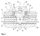
- Figure 2 shows a sectional view of a variant of the laminated plate member according to the invention having a third rigid pane and two electrically heated coatings located on both sides of the rigid central plate.
- a plate heating element 1 is made in the form of a laminated glazing which has a first rigid pane 2, an adhesive layer 3 and a second rigid pane 4.
- the two rigid panes 2 and 4 are preferably prestressed or partially thermally prestressed panes. On their flat side turned towards the adhesive layer 3, each of the two panes is provided with a heating layer 5. Only a portion of the thickness of the rigid pane 2 has been represented and a double line in phantom interrupted transverse to the rigid window 4 indicates that its thickness shown has also been shortened. It is understood that these two rigid panes are significantly thicker than the adhesive layer 3.
- the heating layers 5 consist of compositions and / or successions of layers which are sufficiently resistant to thermal stresses when they function as surface heating layers and which are suitable for the particular application and possibly for the prestressing of the panes.
- Suitable layer systems have been described in many variants in the state of the art, so there is no need to worry about it here. They can be made according to a high transmission of visible light and therefore be transparent.
- a coating which is marketed by the Applicant under the designation "Planitherm 1.3", the number representing its value of k. It is a heat-resistant and prestressed layer system with a silver layer and antireflective dielectric layers on both sides of the layer, which also has reflective properties infrared.
- Suitable means ensure, in a manner known per se, the peripheral passivation of the coatings 5 along the edge, not shown here, of the plate element 1, that is to say that there is no electrically conductive contact or with its outer surface or with its frontal surface, nor risk of an external attack by corrosion of the material of the layers.
- thermoplastic synthetic adhesive material which forms the adhesive layer 3 for example polyvinyl butyral (PVB), ethylene-vinyl acetate (VA)
- a hermetic coating of the border gap for example polyvinyl butyral (PVB), ethylene-vinyl acetate (VA)
- the material of the adhesive layer must be selected so as to be compatible with the material of the coating 5.
- the sectional representation shows the essential components of the power supply of the two heating layers 5 in a common connection area.
- Each of them carries (at least) two plane electrodes 6 which are arranged on both sides of an insulating separation line 7 which isolates from one another two electric poles of the heating layers 5.
- the heating layers 5, which are first deposited in a continuous manner, are divided in a manner known per se in current flow by subsequent structural lines. This defines the current paths between the two pairs of electrodes 6 so that the current flows over the entire surface of the plate member. Current paths not shown here can, without the must be identical for both coatings 5.
- the electrodes 6 of the two layers 5 may also, depending on the needs, be made in the same manner or in different ways. It is not necessary in all cases of application to flow the same currents in both coatings 5 and / or to expect from them the same heating power.
- the electrodes 6 themselves are opaque and can not be visible from the outside. Therefore, they can also be configured as decorative elements, for example representing the logo of a firm or a manufacturer.
- the electrodes 6 can also be deposited below the coatings 5, that is to say before they are deposited on the glass surfaces. They can be produced in the form of thin metal foils or also as strips of screen-printing conductive paste that can be fired (during prestressing of the panes). Suitable electrode embodiments, which are also called collection rails, have been widely described in the state of the art. By coloring the conductive screen printing paste used for producing the electrodes, it is also possible to obtain defined color effects.
- the area of the electrical contact can be masked visually by appropriate means, for example by placing an opaque decoration under it or by printing such a decoration, or also by using a very dark colored glass paste for windows.
- the window 4 carries in the electrode area an opaque coating 8 which is not electrically conductive and which has been printed on the surface of the glass before the deposition of the coating 5 and baked during prestressing.
- a bore or a cutout 9 is formed in the window 4 and in the adhesive layer 3. It (it) serves to pass the external electrical connections of the two pairs of electrodes 6 of the two coatings 5.
- the cut in the adhesive layer 3 is dimensioned before connecting the two rigid panes 2 and 4, so that the adhesive material does not penetrate to the electrodes 6 by fusion. Where appropriate, appropriate protective measures will be taken.
- a insertion piece 10 in the form of a sleeve. Its axial length corresponds substantially to the thickness of the rigid pane 4 (a few millimeters), and it penetrates as far as the plane of the adhesive layer 3.
- a radially protruding projection 11 protrudes outwards from the rear. edge of the bore 9, so that the insert 10 is fixed geometrically to prevent it being extracted.
- This insertion piece must already be placed in the bore 9 before connecting the two rigid panes 2 and 4. It is only during the melting of the thermoplastic adhesive layer 3 that it is permanently fixed. . It can be seen in the drawing that the projection 11 is again taken up by the material of the adhesive layer 3.
- the insertion piece 10 constitutes the mechanical base of a junction box 12.
- Two vertical lines in broken lines indicate a releasably screwed connection between the two parts.
- a support block 13 is fixed in the bore of the insertion piece 10 by the connection box 12. It forms the base of two pairs 14, 15 of spring contacts which are brought into contact with the electrodes 6.
- the inner pair 14 of spring contacts is disposed at the lower end of a short axial appendix of the support block 13. The latter has a diameter or a periphery slightly smaller than the support block 13 itself.
- the spring contacts are placed with direct electrical conduction on the electrodes 6 of the coating 5 of the (lower) glass 2. The supply or heating voltage is fed to the coating of the rigid pane 2 by these contacts 14.
- the spring contacts 14 are sufficient for the intended use of the surface heating element 1 (relatively high supply voltage, alternating current) to the requirements of a safe and durable electrical connection, if necessary, they can in addition, they are welded to the electrodes 6, in particular by means of a suitable preliminary tinning, the necessary heat being preferably provided without contact (by induction or by laser).
- the outer pair of spring contacts 15 exit from the support block 13 at the shoulder which is formed at the transition with its appendix.
- the spring contacts 15 are not in direct contact with the surface electrodes 6 of the heating layer 5 of the rigid pane (upper) 4, because the latter must be terminated on both sides of the bore 9.
- the insertion piece 10 has for this purpose two bridges of On one side, they enter the bore of the insertion piece 10. They terminate on both sides of the appendage of the support block 13 and form the directly complementary elements of the spring contacts 15. the other side, they pass through the wall of the insertion piece 10 and rest on both sides on the (upper) surface of the projection 11 of the insertion piece 10, namely the surface facing the coating 5 of the window 4.
- the projection 11 After inserting and fixing the insertion piece 10 in the bore 9 of the rigid pane 4 and the connection of the two rigid panes 2 and 4, the projection 11 holds the connecting bridges 16 in contact with the flat electrodes (upper) 6.
- the insertion piece 10 is screwed into the junction box 12.
- the projection 11 is pulled under prestressing against the flat electrodes 6 and this contact location is not particularly critical.
- the surfaces of the connecting bridges 16 in contact with the flat electrodes 6 may be roughened or provided with tips to allow some penetration of the connecting bridges in the flat electrodes 6.
- the connecting bridges 16 are preferably fixedly integrated into the insertion piece 10 so that the mounting of the connecting device can be carried out as simply as possible. This can for example be obtained by coating the connecting bridges 16 (narrow strips of sheet metal) with the synthetic material of the insertion piece 10 during its shaping.
- the support block 13 with the spring contacts 14, 15 is inserted into the correct position in the insertion piece 10, possibly by being forced by suitable shaped elements, so that the spring contacts 14, 15 come into contact with each other. with the complementary element each time provided (electrode, bridge contact) and is then fixed.
- the support block 13 can form a fixed entity with the junction box 12 and be fixed together with the latter on the insertion piece 10.
- the axial and radial offset of the pairs 14 and 15 of the spring contacts allows to exclude direct contacts.
- Circuit symbols of a switch 17 and a transistor 18 represent the electrical or electronic equipment of the support block 13 or the junction box 12 and may each correspond to a plurality of corresponding elements.
- other control and switching tasks are assigned to this part of the connection device.
- these switching elements provide controlled voltage supply to one or both coatings according to the corresponding prescriptions of the external control as already explained above.
- connection part using the insertion piece 10 and the support block 13, it is also possible to maintain one or more temperature probes (not shown) in contact with one or more coated panes 2 and 4 for detect the actual temperature in the electrode contact area 6.
- a switching element can then evaluate the measurement values of the temperature sensor and possibly at least momentarily disconnect the current supply to one or both heating layers if the actual temperature should exceed a permissible threshold.
- a switching element which provides protection against temperature overruns and which, in a manner known per se, limits the electrical power consumed to permissible values.
- At least one switch that can have an electronic or electromechanical configuration manages the supply of current to the heating layers.
- This switch can basically be manually connected locally, be controlled by sensors, for example by the temperature sensor or by a window controller. As already indicated, the latter can be part of an automatic regulation of the room temperature (air conditioning system, etc.), but it can basically also be controlled selectively by hand.
- control signals are transmitted wirelessly, a suitable receiver will be provided in the junction box 8 or in the support block 13, in addition to a decoder and other switching means (eg amplifiers). If the control signals are transmitted by lines, appropriate evaluation units will be provided for them, in particular in the case where control signals are transmitted by the mains connection lines anyway and should be filtered. on the spot.
- connection device After manufacture of the connection device and verification of its operation, if necessary, it is still possible to make the transition between the surface of the window and the connection box 12 sealed by a seal 19. In contrast to the representation, one can obviously have this seal, directly between the underside of the junction box 12 and the surface of the glass.
- the junction box 12 overflows slightly above this surface.
- this side of the flat heating element 1 is not turned towards the observer or the user in mounted position and / or is for example placed in front of a wall or in it , the visual perception of the connecting device on the mask (or optionally on the opaque electrode 6 made as a decorative element) remains limited, and otherwise risks by unauthorized or inadvertent manipulation of the connection device are in practice excluded.
- an actuating lever of a control member of the connecting device is to be provided, this will obviously be arranged preferably in a well accessible location, for example near the edge of the flat heating element.
- FIG. 2 elements identical to those of FIG. 1 are provided with the same reference numerals.
- the sheet laminated element is equipped with a third rigid pane 20 (lower) which is connected by surface adhesion to the central rigid pane 2 with the aid of another layer of adhesive 3.
- the surface located at the top in the drawing of the two rigid panes 2 and 20 is provided with a flat heating coating 5.
- the two facing 5 are each provided with a pair of electrodes 6. What was said during The explanation of FIG. 1 also applies to the division of the coatings 5 and the current paths between the electrode pairs 6, as well as for the electrical control and the operating mode in general.
- the rigid pane 2 is traversed by a bore 21 which is oriented substantially axially with respect to the bore 9 of the rigid pane 4.
- the second adhesive layer 3 has a corresponding cutout in which the electrodes 6 of the lower coating.
- An axial extension 22 of the support block 13 is inserted into the bore 21 with the junction box and the support block. Its diameter or, as the case may be, its periphery is smaller than that of the support block 13.
- it In front of the wall of the bore 21, it has a free radial space in order to compensate for possible differences between the centers of the drilled holes 9 and 21 that could result from the manufacture of the laminated pane. It extends in the longitudinal direction until shortly before the surface of the third pane 20 which is located in the laminate.
- contacts between the pairs 14 and 15 of spring contacts are excluded by axial offset and radial offset.
- the spring contacts 14 shown in FIG. 1 are here arranged at the lower end of the appendage 22 and rest with a sufficient contact pressure on the electrodes 6 of the lower cover 5.
- the spring contacts 15 come out of again at the shoulder of the support block 13 which is formed at the transition with the appendix 22. They are located directly on the electrodes 6 of the upper lining 5 of the central pane 2.
Landscapes
- Engineering & Computer Science (AREA)
- General Engineering & Computer Science (AREA)
- Chemical & Material Sciences (AREA)
- Thermal Sciences (AREA)
- Combustion & Propulsion (AREA)
- Mechanical Engineering (AREA)
- Physics & Mathematics (AREA)
- Surface Heating Bodies (AREA)
- Joining Of Glass To Other Materials (AREA)
- Laminated Bodies (AREA)
- Resistance Heating (AREA)
- Fixed Capacitors And Capacitor Manufacturing Machines (AREA)
- Materials For Medical Uses (AREA)
- Securing Of Glass Panes Or The Like (AREA)
Claims (17)
- Verbund-Plattenelement (1) mit mindestens zwei flächig miteinander verklebten starren Scheiben (2, 4), insbesondere Glasscheiben, die jeweils mit einer elektrisch leitfähigen, durch Anlegen einer elektrischen Spannung über Elektroden (6) beheizbaren vollflächigen Beschichtung (5) versehen sind, dadurch gekennzeichnet, dass eine der beiden starren Scheiben in einem Anschlussbereich mit einer Ausnehmung (9) zum Durchführen von elektrischen Außenanschlüssen (12, 14, 15) versehen ist, die mit beiden Beschichtungen (5) mittels flacher Elektroden (6) kontaktiert sind.
- Verbund-Plattenelement nach Anspruch 1, dadurch gekennzeichnet, dass die beiden einander zugewandten Flächen zweier starrer Scheiben (2, 4) beidseits der sie verbindenden Klebeschicht (3) mit den elektrisch leitfähigen Beschichtungen (5) versehen sind.
- Verbund-Plattenelement nach Anspruch 1 oder 2, dadurch gekennzeichnet, dass es mindestens eine dritte flächig verbundene starre Scheibe (20) umfasst, und dass beidseits der mittleren starren Scheibe (4) mindestens eine der elektrisch leitfähigen Beschichtungen (5) vorgesehen ist.
- Verbund-Plattenelement nach einem der vorstehenden Ansprüche, dadurch gekennzeichnet, dass beide oder alle Beschichtungen (5) mittels einer in der Ausnehmung (9) fest angeordneten Anschlusseinrichtung (10, 11, 12) elektrisch kontaktiert sind.
- Verbund-Plattenelement nach einem der vorstehenden Ansprüche, dadurch gekennzeichnet, dass beide oder alle Beschichtungen (5) wahlweise einzeln, in Reihenschaltung und/ oder in Parallelschaltung betreibbar sind.
- Verbund-Plattenelement nach einem der vorstehenden Ansprüche, dadurch gekennzeichnet, dass die Beschichtungen (5) aus demselben Material und/oder Schichtsystem bestehen.
- Verbund-Plattenelement nach einem der vorstehenden Ansprüche 1 bis 5, dadurch gekennzeichnet, dass die Beschichtungen (5) aus unterschiedlichen Materialien und/oder Schichtsystemen bestehen.
- Verbund-Plattenelement nach einem der vorstehenden Ansprüche, dadurch gekennzeichnet, dass der Stromfluss in mindestens einer der Beschichtungen (5) zwischen je zwei in dem Anschlussbereich angeordneten Elektroden (6) entlang einem vorgegebenen Verlauf geleitet wird, der durch lokales isolierendes Unterteilen der Beschichtung erzeugt ist.
- Verbund-Plattenelement nach einem der vorstehenden Ansprüche, gekennzeichnet durch einen Temperaturfühler zum Erfassen einer Isttemperatur der heizbaren Beschichtungen.
- Verbund-Plattenelement nach Anspruch 9, gekennzeichnet durch ein von dem Temperaturfühler steuerbares Schaltelement zum Unterbrechen oder Reduzieren des Heizstroms bei Überschreiten einer vorgegebenen Temperaturschwelle.
- Verbund-Plattenelement nach einem der vorstehenden Ansprüche, dadurch gekennzeichnet, dass zumindest der Anschlussbereich mithilfe einer Kaschierung optisch verdeckt ist.
- Verbund-Plattenelement nach Anspruch 11, dadurch gekennzeichnet, dass die optische Kaschierung durch Verwendung einer opaken Glasmasse für die vorgespannte Glasscheibe (2) erreicht wird.
- Verbund-Plattenelement nach Anspruch 11 oder 12, dadurch gekennzeichnet, dass die optische Kaschierung durch ein opakes Dekor (8) gebildet ist.
- Verbund-Plattenelement nach Anspruch 13, dadurch gekennzeichnet, dass das opake Dekor (8) flächig zwischen der Oberfläche der Glasscheibe (2) und der beheizbaren Beschichtung (5) angeordnet ist.
- Verbund-Plattenelement nach einem der vorstehenden Ansprüche, dadurch gekennzeichnet, dass die Elektroden (6) vor oder nach dem Abscheiden der beheizbaren Beschichtungen (5) durch Auftragen und Einbrennen einer elektrisch leitfähigen Siebdruckpaste hergestellt werden.
- Verbund-Plattenelement nach Anspruch 15, dadurch gekennzeichnet, dass die Elektroden (6) als sichtbare, dekorative Elemente ausgeführt sind.
- Verbund-Plattenelement nach einem der vorstehenden Ansprüche, dadurch gekennzeichnet, dass die Beschichtungen mithilfe lösbarer elektrischer Kontakte, insbesondere mittels Federkontakten (14, 15) elektrisch mit den Außenanschlüssen verbunden sind.
Applications Claiming Priority (3)
| Application Number | Priority Date | Filing Date | Title |
|---|---|---|---|
| DE20308376U DE20308376U1 (de) | 2002-09-10 | 2003-05-28 | Anschlussvorrichtung für ein mehrschichtiges, mit elektrischen Funktionselementen bestücktes Flächenelement und Flächenelement |
| DE10335979A DE10335979A1 (de) | 2003-05-28 | 2003-08-06 | Verbund-Plattenelement mit einer Schichtheizung |
| PCT/FR2004/001301 WO2004110102A1 (fr) | 2003-05-28 | 2004-05-26 | Element feuillete dote d’une couche chauffante |
Publications (2)
| Publication Number | Publication Date |
|---|---|
| EP1627555A1 EP1627555A1 (de) | 2006-02-22 |
| EP1627555B1 true EP1627555B1 (de) | 2006-11-22 |
Family
ID=33512399
Family Applications (1)
| Application Number | Title | Priority Date | Filing Date |
|---|---|---|---|
| EP04767179A Expired - Lifetime EP1627555B1 (de) | 2003-05-28 | 2004-05-26 | Mit einer geheizten schicht ausgestattetes laminiertes element |
Country Status (9)
| Country | Link |
|---|---|
| US (1) | US7423239B2 (de) |
| EP (1) | EP1627555B1 (de) |
| JP (1) | JP4638873B2 (de) |
| KR (1) | KR100985075B1 (de) |
| AT (1) | ATE346476T1 (de) |
| DE (1) | DE602004003370T2 (de) |
| DK (1) | DK1627555T3 (de) |
| ES (1) | ES2277289T3 (de) |
| WO (1) | WO2004110102A1 (de) |
Cited By (1)
| Publication number | Priority date | Publication date | Assignee | Title |
|---|---|---|---|---|
| EP2412521A1 (de) | 2010-07-29 | 2012-02-01 | Saint-Gobain Glass France | Beleuchteter Heizkörper |
Families Citing this family (18)
| Publication number | Priority date | Publication date | Assignee | Title |
|---|---|---|---|---|
| EP2532388A3 (de) | 2005-02-16 | 2013-03-06 | Md Bioalpha Co., Ltd. | Pharmazeutische Zusammensetzung zur Behandlung oder Vorbeugung von Krankheiten einschließlich Adipositas, Diabetes, metabolisches Syndrom, neurodegenerativer Erkrankungen und Dysfunktion der Mitochondrien |
| WO2007057461A1 (fr) * | 2005-11-21 | 2007-05-24 | Agc Flat Glass Europe Sa | Vitrage feuillete et procede de fabrication d'un vitrage feuillete |
| WO2007057463A1 (fr) * | 2005-11-21 | 2007-05-24 | Agc Flat Glass Europe Sa | Vitrage feuilleté et procédé de fabrication d'un vitrage feuilleté |
| AT504216B1 (de) * | 2006-12-18 | 2008-04-15 | Zorn Heinz | Beheizbares element |
| WO2009001264A1 (en) * | 2007-06-27 | 2008-12-31 | Koninklijke Philips Electronics N.V. | Light output device |
| US8203105B2 (en) * | 2008-07-18 | 2012-06-19 | Advanced Materials Enterprises Company Limited | Nano thickness heating material coated food warmer devices for hospital and elsewhere daily usage |
| DE102009026021A1 (de) * | 2009-06-24 | 2010-12-30 | Saint-Gobain Sekurit Deutschland Gmbh & Co. Kg | Scheibe mit beheizbaren, optisch transparenten Sensorfeld |
| EP2280228A1 (de) * | 2009-06-25 | 2011-02-02 | Inca Heating Products | Aktives Wandelement, Wandheizsystem damit und Verfahren zur Herstellung eines Gebäudes |
| WO2012126708A1 (de) | 2011-03-22 | 2012-09-27 | Saint-Gobain Glass France | Verfahren und anordnung zum enteisen einer transparenten scheibe mit elektrischer heizeinrichtung |
| JP6171876B2 (ja) * | 2012-11-14 | 2017-08-02 | 旭硝子株式会社 | 給電構造及びそれを備えた窓用樹脂製板状体、並びに給電構造を備えた窓用樹脂製板状体の製造方法 |
| EP2955164B1 (de) * | 2013-02-05 | 2021-02-17 | Nippon Sheet Glass Co., Ltd. | Verbundglas |
| FR3002528B1 (fr) * | 2013-02-26 | 2015-10-09 | Saint Gobain | Renfort d'orifice de vitrage |
| ES2904881T3 (es) * | 2014-06-09 | 2022-04-06 | BABA Mitsuko | Cuerpo generador de calor |
| US10562274B1 (en) | 2016-02-22 | 2020-02-18 | Apple Inc. | Glass fastening and sealing systems |
| FR3062593A1 (fr) * | 2017-02-03 | 2018-08-10 | Saint-Gobain Glass France | Procede de fabrication d'un vitrage feuillete dont une seule feuille de verre presente un trou traversant |
| FR3062594B1 (fr) * | 2017-02-03 | 2019-03-22 | Saint-Gobain Glass France | Vitrage feuillete dont une seule feuille de verre presente un trou traversant |
| WO2020016367A1 (de) * | 2018-07-20 | 2020-01-23 | Saint-Gobain Glass France | Vorrichtung und verfahren zum verlöten von kontaktelementen mit induktionswärme |
| CZ308078B6 (cs) * | 2018-11-30 | 2019-12-18 | Thermo Glass.eu s.r.o. | Topné bezpečnostní zasklení |
Family Cites Families (22)
| Publication number | Priority date | Publication date | Assignee | Title |
|---|---|---|---|---|
| JPS5060513A (de) * | 1973-09-28 | 1975-05-24 | ||
| US3918783A (en) * | 1974-04-17 | 1975-11-11 | Essex International Inc | Apparatus for electrically connecting conductors on glass substrates |
| JPH0119345Y2 (de) * | 1981-02-21 | 1989-06-05 | ||
| US4691486A (en) * | 1982-04-29 | 1987-09-08 | Frank Niekrasz | Glass assembly for refrigerator doors and method of manufacture |
| JPS62249383A (ja) * | 1986-04-22 | 1987-10-30 | 日立電線株式会社 | 面状発熱体 |
| US4786784A (en) * | 1987-02-17 | 1988-11-22 | Libbey-Owens-Ford Co. | Method for producing an electrically heated window assembly and resulting article |
| JPS63149935U (de) * | 1987-03-19 | 1988-10-03 | ||
| US4782216A (en) * | 1987-08-11 | 1988-11-01 | Monsanto Company | Electrically heatable laminated window |
| US4918288A (en) * | 1988-11-04 | 1990-04-17 | Ppg Industries, Inc. | Electrical lead arrangement for a heatable transparency |
| FR2646968B1 (fr) * | 1989-05-12 | 1991-08-30 | Boyeldieu Andre | Dispositif de connexion pour circuit de chauffage et de desembuage d'une glace |
| LU87797A1 (fr) * | 1990-08-31 | 1992-03-11 | Glaverbel | Miroir chauffant |
| DE9016664U1 (de) * | 1990-12-08 | 1991-02-28 | Vegla Vereinigte Glaswerke Gmbh, 5100 Aachen, De | |
| US5408069A (en) * | 1993-09-28 | 1995-04-18 | Mischel, Jr.; James V. | Self-defogging mirror |
| GB9418477D0 (en) * | 1994-09-14 | 1994-11-02 | Glaverbel | A heated glazing panel and a control circuit for use therewith |
| JPH1022065A (ja) * | 1996-07-04 | 1998-01-23 | Nec Eng Ltd | シートヒータ |
| JPH1064669A (ja) * | 1996-08-21 | 1998-03-06 | Tokyo Cosmos Electric Co Ltd | ミラー用面状発熱体とその製法 |
| JP3906567B2 (ja) | 1998-06-19 | 2007-04-18 | 株式会社豊田自動織機 | 樹脂ウインドの端子固定構造 |
| US6475043B2 (en) * | 1998-11-25 | 2002-11-05 | Antaya Technologies Corporation | Circular electrical connector |
| DE19860870A1 (de) * | 1998-12-31 | 2000-07-06 | Heiko Gros | Scheibenheizung für Scheiben in Fenstern und Türen |
| JP2000283482A (ja) * | 1999-03-31 | 2000-10-13 | Figla Co Ltd | 発熱機能を有する積層体及び電極部の取出構造 |
| DE19922778A1 (de) * | 1999-05-18 | 2000-11-23 | Mekra Lang Gmbh & Co Kg | Beheizbarer Rückspiegel |
| DE10208552B4 (de) | 2002-02-27 | 2006-03-02 | Saint-Gobain Glass Deutschland Gmbh | Elektrisch beheizbare vorgespannte Glasscheibe |
-
2004
- 2004-05-26 US US10/558,472 patent/US7423239B2/en active Active
- 2004-05-26 JP JP2006530383A patent/JP4638873B2/ja not_active Expired - Fee Related
- 2004-05-26 EP EP04767179A patent/EP1627555B1/de not_active Expired - Lifetime
- 2004-05-26 ES ES04767179T patent/ES2277289T3/es not_active Expired - Lifetime
- 2004-05-26 KR KR1020057022444A patent/KR100985075B1/ko active IP Right Grant
- 2004-05-26 WO PCT/FR2004/001301 patent/WO2004110102A1/fr active IP Right Grant
- 2004-05-26 AT AT04767179T patent/ATE346476T1/de not_active IP Right Cessation
- 2004-05-26 DK DK04767179T patent/DK1627555T3/da active
- 2004-05-26 DE DE602004003370T patent/DE602004003370T2/de not_active Expired - Lifetime
Cited By (1)
| Publication number | Priority date | Publication date | Assignee | Title |
|---|---|---|---|---|
| EP2412521A1 (de) | 2010-07-29 | 2012-02-01 | Saint-Gobain Glass France | Beleuchteter Heizkörper |
Also Published As
| Publication number | Publication date |
|---|---|
| US7423239B2 (en) | 2008-09-09 |
| WO2004110102A1 (fr) | 2004-12-16 |
| ES2277289T3 (es) | 2007-07-01 |
| JP2007500807A (ja) | 2007-01-18 |
| DK1627555T3 (da) | 2007-03-19 |
| KR100985075B1 (ko) | 2010-10-04 |
| ATE346476T1 (de) | 2006-12-15 |
| US20060292380A1 (en) | 2006-12-28 |
| EP1627555A1 (de) | 2006-02-22 |
| KR20060017813A (ko) | 2006-02-27 |
| DE602004003370T2 (de) | 2007-09-27 |
| JP4638873B2 (ja) | 2011-02-23 |
| DE602004003370D1 (de) | 2007-01-04 |
Similar Documents
| Publication | Publication Date | Title |
|---|---|---|
| EP1627555B1 (de) | Mit einer geheizten schicht ausgestattetes laminiertes element | |
| EP1803327B1 (de) | Mit einer widerstands-heizbeschichtung ausgestattete transparente fensterscheibe | |
| EP1980137B1 (de) | Transparente verglasung mit laminiertem heizsystem | |
| EP2861422B1 (de) | Glasdach mit leuchtmitteln und solchen zur kontrolle der lichttransmission | |
| EP1537762B1 (de) | Verbindungseinrichtung für ein flächiges element mit mehreren schichten ausgestattet mit elektrischen funktionselementen und flächiges element | |
| EP2861421B1 (de) | Glasdach mit leuchtvorrichtung | |
| CA2469708C (fr) | Vitre chauffante avec un revetement superficiel electriquement conducteur | |
| EP1459602B1 (de) | Laminierte glasscheibe mit elektrisch gesteuertem funktionalelement | |
| BE1021978B1 (fr) | Vitrage automobile | |
| WO2017005627A1 (fr) | Vitrage automobile | |
| EP2127475A2 (de) | Transparentes glas mit erwärmungsbeschichtung | |
| EP1559296B1 (de) | Transparentes fenster mit nichttransparenter kontaktfläche für l t-bond-verbindung | |
| FR2875669A1 (fr) | Structure chauffante electrique | |
| BE1005038A5 (fr) | Miroir chauffant. | |
| EP1439600B1 (de) | Anschlusselement durch Löten | |
| EP1629697B1 (de) | Plattenelement für geschichtete erwärmung |
Legal Events
| Date | Code | Title | Description |
|---|---|---|---|
| PUAI | Public reference made under article 153(3) epc to a published international application that has entered the european phase |
Free format text: ORIGINAL CODE: 0009012 |
|
| 17P | Request for examination filed |
Effective date: 20051014 |
|
| AK | Designated contracting states |
Kind code of ref document: A1 Designated state(s): AT BE BG CH CY CZ DE DK EE ES FI FR GB GR HU IE IT LI LU MC NL PL PT RO SE SI SK TR |
|
| GRAP | Despatch of communication of intention to grant a patent |
Free format text: ORIGINAL CODE: EPIDOSNIGR1 |
|
| DAX | Request for extension of the european patent (deleted) | ||
| GRAS | Grant fee paid |
Free format text: ORIGINAL CODE: EPIDOSNIGR3 |
|
| GRAA | (expected) grant |
Free format text: ORIGINAL CODE: 0009210 |
|
| AK | Designated contracting states |
Kind code of ref document: B1 Designated state(s): AT BE BG CH CY CZ DE DK EE ES FI FR GB GR HU IE IT LI LU MC NL PL PT RO SE SI SK TR |
|
| PG25 | Lapsed in a contracting state [announced via postgrant information from national office to epo] |
Ref country code: IE Free format text: LAPSE BECAUSE OF FAILURE TO SUBMIT A TRANSLATION OF THE DESCRIPTION OR TO PAY THE FEE WITHIN THE PRESCRIBED TIME-LIMIT Effective date: 20061122 Ref country code: SI Free format text: LAPSE BECAUSE OF FAILURE TO SUBMIT A TRANSLATION OF THE DESCRIPTION OR TO PAY THE FEE WITHIN THE PRESCRIBED TIME-LIMIT Effective date: 20061122 Ref country code: RO Free format text: LAPSE BECAUSE OF FAILURE TO SUBMIT A TRANSLATION OF THE DESCRIPTION OR TO PAY THE FEE WITHIN THE PRESCRIBED TIME-LIMIT Effective date: 20061122 Ref country code: NL Free format text: LAPSE BECAUSE OF FAILURE TO SUBMIT A TRANSLATION OF THE DESCRIPTION OR TO PAY THE FEE WITHIN THE PRESCRIBED TIME-LIMIT Effective date: 20061122 Ref country code: AT Free format text: LAPSE BECAUSE OF FAILURE TO SUBMIT A TRANSLATION OF THE DESCRIPTION OR TO PAY THE FEE WITHIN THE PRESCRIBED TIME-LIMIT Effective date: 20061122 Ref country code: CZ Free format text: LAPSE BECAUSE OF FAILURE TO SUBMIT A TRANSLATION OF THE DESCRIPTION OR TO PAY THE FEE WITHIN THE PRESCRIBED TIME-LIMIT Effective date: 20061122 Ref country code: SK Free format text: LAPSE BECAUSE OF FAILURE TO SUBMIT A TRANSLATION OF THE DESCRIPTION OR TO PAY THE FEE WITHIN THE PRESCRIBED TIME-LIMIT Effective date: 20061122 Ref country code: PL Free format text: LAPSE BECAUSE OF FAILURE TO SUBMIT A TRANSLATION OF THE DESCRIPTION OR TO PAY THE FEE WITHIN THE PRESCRIBED TIME-LIMIT Effective date: 20061122 Ref country code: FI Free format text: LAPSE BECAUSE OF FAILURE TO SUBMIT A TRANSLATION OF THE DESCRIPTION OR TO PAY THE FEE WITHIN THE PRESCRIBED TIME-LIMIT Effective date: 20061122 |
|
| REG | Reference to a national code |
Ref country code: GB Ref legal event code: FG4D Free format text: NOT ENGLISH |
|
| REG | Reference to a national code |
Ref country code: CH Ref legal event code: EP |
|
| REG | Reference to a national code |
Ref country code: IE Ref legal event code: FG4D Free format text: LANGUAGE OF EP DOCUMENT: FRENCH |
|
| REF | Corresponds to: |
Ref document number: 602004003370 Country of ref document: DE Date of ref document: 20070104 Kind code of ref document: P |
|
| PG25 | Lapsed in a contracting state [announced via postgrant information from national office to epo] |
Ref country code: BG Free format text: LAPSE BECAUSE OF FAILURE TO SUBMIT A TRANSLATION OF THE DESCRIPTION OR TO PAY THE FEE WITHIN THE PRESCRIBED TIME-LIMIT Effective date: 20070222 |
|
| REG | Reference to a national code |
Ref country code: SE Ref legal event code: TRGR |
|
| GBT | Gb: translation of ep patent filed (gb section 77(6)(a)/1977) |
Effective date: 20070207 |
|
| REG | Reference to a national code |
Ref country code: DK Ref legal event code: T3 |
|
| PG25 | Lapsed in a contracting state [announced via postgrant information from national office to epo] |
Ref country code: PT Free format text: LAPSE BECAUSE OF FAILURE TO SUBMIT A TRANSLATION OF THE DESCRIPTION OR TO PAY THE FEE WITHIN THE PRESCRIBED TIME-LIMIT Effective date: 20070423 |
|
| NLV1 | Nl: lapsed or annulled due to failure to fulfill the requirements of art. 29p and 29m of the patents act | ||
| REG | Reference to a national code |
Ref country code: IE Ref legal event code: FD4D |
|
| REG | Reference to a national code |
Ref country code: ES Ref legal event code: FG2A Ref document number: 2277289 Country of ref document: ES Kind code of ref document: T3 |
|
| PLBE | No opposition filed within time limit |
Free format text: ORIGINAL CODE: 0009261 |
|
| STAA | Information on the status of an ep patent application or granted ep patent |
Free format text: STATUS: NO OPPOSITION FILED WITHIN TIME LIMIT |
|
| 26N | No opposition filed |
Effective date: 20070823 |
|
| BERE | Be: lapsed |
Owner name: SAINT-GOBAIN GLASS FRANCE Effective date: 20070531 |
|
| PG25 | Lapsed in a contracting state [announced via postgrant information from national office to epo] |
Ref country code: MC Free format text: LAPSE BECAUSE OF NON-PAYMENT OF DUE FEES Effective date: 20070531 |
|
| PG25 | Lapsed in a contracting state [announced via postgrant information from national office to epo] |
Ref country code: BE Free format text: LAPSE BECAUSE OF NON-PAYMENT OF DUE FEES Effective date: 20070531 |
|
| PG25 | Lapsed in a contracting state [announced via postgrant information from national office to epo] |
Ref country code: GR Free format text: LAPSE BECAUSE OF FAILURE TO SUBMIT A TRANSLATION OF THE DESCRIPTION OR TO PAY THE FEE WITHIN THE PRESCRIBED TIME-LIMIT Effective date: 20070223 |
|
| REG | Reference to a national code |
Ref country code: CH Ref legal event code: PL |
|
| PG25 | Lapsed in a contracting state [announced via postgrant information from national office to epo] |
Ref country code: CH Free format text: LAPSE BECAUSE OF NON-PAYMENT OF DUE FEES Effective date: 20080531 Ref country code: LI Free format text: LAPSE BECAUSE OF NON-PAYMENT OF DUE FEES Effective date: 20080531 Ref country code: EE Free format text: LAPSE BECAUSE OF FAILURE TO SUBMIT A TRANSLATION OF THE DESCRIPTION OR TO PAY THE FEE WITHIN THE PRESCRIBED TIME-LIMIT Effective date: 20061122 |
|
| PG25 | Lapsed in a contracting state [announced via postgrant information from national office to epo] |
Ref country code: CY Free format text: LAPSE BECAUSE OF FAILURE TO SUBMIT A TRANSLATION OF THE DESCRIPTION OR TO PAY THE FEE WITHIN THE PRESCRIBED TIME-LIMIT Effective date: 20061122 Ref country code: LU Free format text: LAPSE BECAUSE OF NON-PAYMENT OF DUE FEES Effective date: 20070526 |
|
| PG25 | Lapsed in a contracting state [announced via postgrant information from national office to epo] |
Ref country code: HU Free format text: LAPSE BECAUSE OF FAILURE TO SUBMIT A TRANSLATION OF THE DESCRIPTION OR TO PAY THE FEE WITHIN THE PRESCRIBED TIME-LIMIT Effective date: 20070523 |
|
| REG | Reference to a national code |
Ref country code: FR Ref legal event code: PLFP Year of fee payment: 12 |
|
| REG | Reference to a national code |
Ref country code: FR Ref legal event code: PLFP Year of fee payment: 13 |
|
| REG | Reference to a national code |
Ref country code: FR Ref legal event code: PLFP Year of fee payment: 14 |
|
| REG | Reference to a national code |
Ref country code: FR Ref legal event code: PLFP Year of fee payment: 15 |
|
| PGFP | Annual fee paid to national office [announced via postgrant information from national office to epo] |
Ref country code: SE Payment date: 20200512 Year of fee payment: 17 |
|
| REG | Reference to a national code |
Ref country code: SE Ref legal event code: EUG |
|
| PG25 | Lapsed in a contracting state [announced via postgrant information from national office to epo] |
Ref country code: SE Free format text: LAPSE BECAUSE OF NON-PAYMENT OF DUE FEES Effective date: 20210527 |
|
| PGFP | Annual fee paid to national office [announced via postgrant information from national office to epo] |
Ref country code: IT Payment date: 20230412 Year of fee payment: 20 Ref country code: FR Payment date: 20230531 Year of fee payment: 20 Ref country code: ES Payment date: 20230605 Year of fee payment: 20 Ref country code: DK Payment date: 20230511 Year of fee payment: 20 Ref country code: DE Payment date: 20230331 Year of fee payment: 20 |
|
| PGFP | Annual fee paid to national office [announced via postgrant information from national office to epo] |
Ref country code: TR Payment date: 20230524 Year of fee payment: 20 |
|
| PGFP | Annual fee paid to national office [announced via postgrant information from national office to epo] |
Ref country code: GB Payment date: 20230406 Year of fee payment: 20 |
|
| REG | Reference to a national code |
Ref country code: DE Ref legal event code: R082 Ref document number: 602004003370 Country of ref document: DE Representative=s name: OBERMAIR, CHRISTIAN, DR. RER. NAT., DE |