EP1537762B1 - Verbindungseinrichtung für ein flächiges element mit mehreren schichten ausgestattet mit elektrischen funktionselementen und flächiges element - Google Patents
Verbindungseinrichtung für ein flächiges element mit mehreren schichten ausgestattet mit elektrischen funktionselementen und flächiges element Download PDFInfo
- Publication number
- EP1537762B1 EP1537762B1 EP03769575A EP03769575A EP1537762B1 EP 1537762 B1 EP1537762 B1 EP 1537762B1 EP 03769575 A EP03769575 A EP 03769575A EP 03769575 A EP03769575 A EP 03769575A EP 1537762 B1 EP1537762 B1 EP 1537762B1
- Authority
- EP
- European Patent Office
- Prior art keywords
- flat element
- connector according
- cutout
- flat
- heating layer
- Prior art date
- Legal status (The legal status is an assumption and is not a legal conclusion. Google has not performed a legal analysis and makes no representation as to the accuracy of the status listed.)
- Expired - Lifetime
Links
- 239000010410 layer Substances 0.000 claims description 82
- 238000010438 heat treatment Methods 0.000 claims description 77
- 239000000523 sample Substances 0.000 claims description 9
- 239000012799 electrically-conductive coating Substances 0.000 claims description 7
- 238000000926 separation method Methods 0.000 claims description 5
- 230000003287 optical effect Effects 0.000 claims description 2
- 239000011229 interlayer Substances 0.000 claims 1
- 239000011521 glass Substances 0.000 description 13
- 239000004020 conductor Substances 0.000 description 11
- 239000000463 material Substances 0.000 description 11
- 239000002131 composite material Substances 0.000 description 9
- 238000012856 packing Methods 0.000 description 7
- 238000000576 coating method Methods 0.000 description 6
- 238000003466 welding Methods 0.000 description 6
- 239000011248 coating agent Substances 0.000 description 5
- 239000012790 adhesive layer Substances 0.000 description 4
- 238000004519 manufacturing process Methods 0.000 description 4
- 239000000853 adhesive Substances 0.000 description 3
- 230000001070 adhesive effect Effects 0.000 description 3
- 229910052751 metal Inorganic materials 0.000 description 3
- 239000002184 metal Substances 0.000 description 3
- 238000000034 method Methods 0.000 description 3
- 230000035515 penetration Effects 0.000 description 3
- 239000000758 substrate Substances 0.000 description 3
- 229920002994 synthetic fiber Polymers 0.000 description 3
- 238000012546 transfer Methods 0.000 description 3
- 230000001464 adherent effect Effects 0.000 description 2
- 210000003423 ankle Anatomy 0.000 description 2
- 238000010276 construction Methods 0.000 description 2
- 238000001514 detection method Methods 0.000 description 2
- 230000000694 effects Effects 0.000 description 2
- 238000012423 maintenance Methods 0.000 description 2
- 238000002844 melting Methods 0.000 description 2
- 230000008018 melting Effects 0.000 description 2
- 230000002093 peripheral effect Effects 0.000 description 2
- 229920002037 poly(vinyl butyral) polymer Polymers 0.000 description 2
- 229910052709 silver Inorganic materials 0.000 description 2
- 239000004332 silver Substances 0.000 description 2
- 229920001169 thermoplastic Polymers 0.000 description 2
- 239000004416 thermosoftening plastic Substances 0.000 description 2
- XTXRWKRVRITETP-UHFFFAOYSA-N Vinyl acetate Chemical compound CC(=O)OC=C XTXRWKRVRITETP-UHFFFAOYSA-N 0.000 description 1
- 230000006978 adaptation Effects 0.000 description 1
- 238000004378 air conditioning Methods 0.000 description 1
- 230000003667 anti-reflective effect Effects 0.000 description 1
- 230000004323 axial length Effects 0.000 description 1
- 210000003323 beak Anatomy 0.000 description 1
- 230000033228 biological regulation Effects 0.000 description 1
- 230000005540 biological transmission Effects 0.000 description 1
- 230000000903 blocking effect Effects 0.000 description 1
- DQXBYHZEEUGOBF-UHFFFAOYSA-N but-3-enoic acid;ethene Chemical compound C=C.OC(=O)CC=C DQXBYHZEEUGOBF-UHFFFAOYSA-N 0.000 description 1
- 239000003086 colorant Substances 0.000 description 1
- 230000000295 complement effect Effects 0.000 description 1
- 230000007797 corrosion Effects 0.000 description 1
- 238000005260 corrosion Methods 0.000 description 1
- 238000005520 cutting process Methods 0.000 description 1
- 238000005034 decoration Methods 0.000 description 1
- 230000032798 delamination Effects 0.000 description 1
- 230000001419 dependent effect Effects 0.000 description 1
- 238000013461 design Methods 0.000 description 1
- 230000002542 deteriorative effect Effects 0.000 description 1
- 238000011161 development Methods 0.000 description 1
- 230000018109 developmental process Effects 0.000 description 1
- 238000009826 distribution Methods 0.000 description 1
- 238000004043 dyeing Methods 0.000 description 1
- 239000005038 ethylene vinyl acetate Substances 0.000 description 1
- 238000011156 evaluation Methods 0.000 description 1
- 238000000605 extraction Methods 0.000 description 1
- 239000010408 film Substances 0.000 description 1
- 230000006698 induction Effects 0.000 description 1
- 238000003780 insertion Methods 0.000 description 1
- 230000037431 insertion Effects 0.000 description 1
- 238000009434 installation Methods 0.000 description 1
- 238000009413 insulation Methods 0.000 description 1
- 230000000873 masking effect Effects 0.000 description 1
- 239000000203 mixture Substances 0.000 description 1
- 238000013021 overheating Methods 0.000 description 1
- 229920003023 plastic Polymers 0.000 description 1
- 239000004033 plastic Substances 0.000 description 1
- 229920001200 poly(ethylene-vinyl acetate) Polymers 0.000 description 1
- 238000001556 precipitation Methods 0.000 description 1
- 230000036316 preload Effects 0.000 description 1
- 230000005855 radiation Effects 0.000 description 1
- 230000003014 reinforcing effect Effects 0.000 description 1
- 238000010079 rubber tapping Methods 0.000 description 1
- 238000007789 sealing Methods 0.000 description 1
- 238000007493 shaping process Methods 0.000 description 1
- 238000005476 soldering Methods 0.000 description 1
- 239000013589 supplement Substances 0.000 description 1
- 238000012360 testing method Methods 0.000 description 1
- 239000010409 thin film Substances 0.000 description 1
- 230000007704 transition Effects 0.000 description 1
Images
Classifications
-
- H—ELECTRICITY
- H01—ELECTRIC ELEMENTS
- H01R—ELECTRICALLY-CONDUCTIVE CONNECTIONS; STRUCTURAL ASSOCIATIONS OF A PLURALITY OF MUTUALLY-INSULATED ELECTRICAL CONNECTING ELEMENTS; COUPLING DEVICES; CURRENT COLLECTORS
- H01R13/00—Details of coupling devices of the kinds covered by groups H01R12/70 or H01R24/00 - H01R33/00
- H01R13/02—Contact members
- H01R13/22—Contacts for co-operating by abutting
- H01R13/24—Contacts for co-operating by abutting resilient; resiliently-mounted
- H01R13/2442—Contacts for co-operating by abutting resilient; resiliently-mounted with a single cantilevered beam
-
- H—ELECTRICITY
- H01—ELECTRIC ELEMENTS
- H01R—ELECTRICALLY-CONDUCTIVE CONNECTIONS; STRUCTURAL ASSOCIATIONS OF A PLURALITY OF MUTUALLY-INSULATED ELECTRICAL CONNECTING ELEMENTS; COUPLING DEVICES; CURRENT COLLECTORS
- H01R4/00—Electrically-conductive connections between two or more conductive members in direct contact, i.e. touching one another; Means for effecting or maintaining such contact; Electrically-conductive connections having two or more spaced connecting locations for conductors and using contact members penetrating insulation
- H01R4/28—Clamped connections, spring connections
- H01R4/48—Clamped connections, spring connections utilising a spring, clip, or other resilient member
-
- B—PERFORMING OPERATIONS; TRANSPORTING
- B32—LAYERED PRODUCTS
- B32B—LAYERED PRODUCTS, i.e. PRODUCTS BUILT-UP OF STRATA OF FLAT OR NON-FLAT, e.g. CELLULAR OR HONEYCOMB, FORM
- B32B17/00—Layered products essentially comprising sheet glass, or glass, slag, or like fibres
- B32B17/06—Layered products essentially comprising sheet glass, or glass, slag, or like fibres comprising glass as the main or only constituent of a layer, next to another layer of a specific material
- B32B17/10—Layered products essentially comprising sheet glass, or glass, slag, or like fibres comprising glass as the main or only constituent of a layer, next to another layer of a specific material of synthetic resin
- B32B17/10005—Layered products essentially comprising sheet glass, or glass, slag, or like fibres comprising glass as the main or only constituent of a layer, next to another layer of a specific material of synthetic resin laminated safety glass or glazing
- B32B17/10009—Layered products essentially comprising sheet glass, or glass, slag, or like fibres comprising glass as the main or only constituent of a layer, next to another layer of a specific material of synthetic resin laminated safety glass or glazing characterized by the number, the constitution or treatment of glass sheets
- B32B17/10036—Layered products essentially comprising sheet glass, or glass, slag, or like fibres comprising glass as the main or only constituent of a layer, next to another layer of a specific material of synthetic resin laminated safety glass or glazing characterized by the number, the constitution or treatment of glass sheets comprising two outer glass sheets
- B32B17/10045—Layered products essentially comprising sheet glass, or glass, slag, or like fibres comprising glass as the main or only constituent of a layer, next to another layer of a specific material of synthetic resin laminated safety glass or glazing characterized by the number, the constitution or treatment of glass sheets comprising two outer glass sheets with at least one intermediate layer consisting of a glass sheet
-
- B—PERFORMING OPERATIONS; TRANSPORTING
- B32—LAYERED PRODUCTS
- B32B—LAYERED PRODUCTS, i.e. PRODUCTS BUILT-UP OF STRATA OF FLAT OR NON-FLAT, e.g. CELLULAR OR HONEYCOMB, FORM
- B32B17/00—Layered products essentially comprising sheet glass, or glass, slag, or like fibres
- B32B17/06—Layered products essentially comprising sheet glass, or glass, slag, or like fibres comprising glass as the main or only constituent of a layer, next to another layer of a specific material
- B32B17/10—Layered products essentially comprising sheet glass, or glass, slag, or like fibres comprising glass as the main or only constituent of a layer, next to another layer of a specific material of synthetic resin
- B32B17/10005—Layered products essentially comprising sheet glass, or glass, slag, or like fibres comprising glass as the main or only constituent of a layer, next to another layer of a specific material of synthetic resin laminated safety glass or glazing
- B32B17/10165—Functional features of the laminated safety glass or glazing
- B32B17/10174—Coatings of a metallic or dielectric material on a constituent layer of glass or polymer
-
- B—PERFORMING OPERATIONS; TRANSPORTING
- B32—LAYERED PRODUCTS
- B32B—LAYERED PRODUCTS, i.e. PRODUCTS BUILT-UP OF STRATA OF FLAT OR NON-FLAT, e.g. CELLULAR OR HONEYCOMB, FORM
- B32B17/00—Layered products essentially comprising sheet glass, or glass, slag, or like fibres
- B32B17/06—Layered products essentially comprising sheet glass, or glass, slag, or like fibres comprising glass as the main or only constituent of a layer, next to another layer of a specific material
- B32B17/10—Layered products essentially comprising sheet glass, or glass, slag, or like fibres comprising glass as the main or only constituent of a layer, next to another layer of a specific material of synthetic resin
- B32B17/10005—Layered products essentially comprising sheet glass, or glass, slag, or like fibres comprising glass as the main or only constituent of a layer, next to another layer of a specific material of synthetic resin laminated safety glass or glazing
- B32B17/1055—Layered products essentially comprising sheet glass, or glass, slag, or like fibres comprising glass as the main or only constituent of a layer, next to another layer of a specific material of synthetic resin laminated safety glass or glazing characterized by the resin layer, i.e. interlayer
- B32B17/10761—Layered products essentially comprising sheet glass, or glass, slag, or like fibres comprising glass as the main or only constituent of a layer, next to another layer of a specific material of synthetic resin laminated safety glass or glazing characterized by the resin layer, i.e. interlayer containing vinyl acetal
-
- B—PERFORMING OPERATIONS; TRANSPORTING
- B32—LAYERED PRODUCTS
- B32B—LAYERED PRODUCTS, i.e. PRODUCTS BUILT-UP OF STRATA OF FLAT OR NON-FLAT, e.g. CELLULAR OR HONEYCOMB, FORM
- B32B17/00—Layered products essentially comprising sheet glass, or glass, slag, or like fibres
- B32B17/06—Layered products essentially comprising sheet glass, or glass, slag, or like fibres comprising glass as the main or only constituent of a layer, next to another layer of a specific material
- B32B17/10—Layered products essentially comprising sheet glass, or glass, slag, or like fibres comprising glass as the main or only constituent of a layer, next to another layer of a specific material of synthetic resin
- B32B17/10005—Layered products essentially comprising sheet glass, or glass, slag, or like fibres comprising glass as the main or only constituent of a layer, next to another layer of a specific material of synthetic resin laminated safety glass or glazing
- B32B17/1055—Layered products essentially comprising sheet glass, or glass, slag, or like fibres comprising glass as the main or only constituent of a layer, next to another layer of a specific material of synthetic resin laminated safety glass or glazing characterized by the resin layer, i.e. interlayer
- B32B17/10788—Layered products essentially comprising sheet glass, or glass, slag, or like fibres comprising glass as the main or only constituent of a layer, next to another layer of a specific material of synthetic resin laminated safety glass or glazing characterized by the resin layer, i.e. interlayer containing ethylene vinylacetate
-
- F—MECHANICAL ENGINEERING; LIGHTING; HEATING; WEAPONS; BLASTING
- F24—HEATING; RANGES; VENTILATING
- F24D—DOMESTIC- OR SPACE-HEATING SYSTEMS, e.g. CENTRAL HEATING SYSTEMS; DOMESTIC HOT-WATER SUPPLY SYSTEMS; ELEMENTS OR COMPONENTS THEREFOR
- F24D13/00—Electric heating systems
- F24D13/02—Electric heating systems solely using resistance heating, e.g. underfloor heating
- F24D13/022—Electric heating systems solely using resistance heating, e.g. underfloor heating resistances incorporated in construction elements
-
- H—ELECTRICITY
- H01—ELECTRIC ELEMENTS
- H01R—ELECTRICALLY-CONDUCTIVE CONNECTIONS; STRUCTURAL ASSOCIATIONS OF A PLURALITY OF MUTUALLY-INSULATED ELECTRICAL CONNECTING ELEMENTS; COUPLING DEVICES; CURRENT COLLECTORS
- H01R12/00—Structural associations of a plurality of mutually-insulated electrical connecting elements, specially adapted for printed circuits, e.g. printed circuit boards [PCB], flat or ribbon cables, or like generally planar structures, e.g. terminal strips, terminal blocks; Coupling devices specially adapted for printed circuits, flat or ribbon cables, or like generally planar structures; Terminals specially adapted for contact with, or insertion into, printed circuits, flat or ribbon cables, or like generally planar structures
- H01R12/50—Fixed connections
- H01R12/51—Fixed connections for rigid printed circuits or like structures
- H01R12/55—Fixed connections for rigid printed circuits or like structures characterised by the terminals
-
- H—ELECTRICITY
- H05—ELECTRIC TECHNIQUES NOT OTHERWISE PROVIDED FOR
- H05B—ELECTRIC HEATING; ELECTRIC LIGHT SOURCES NOT OTHERWISE PROVIDED FOR; CIRCUIT ARRANGEMENTS FOR ELECTRIC LIGHT SOURCES, IN GENERAL
- H05B3/00—Ohmic-resistance heating
- H05B3/84—Heating arrangements specially adapted for transparent or reflecting areas, e.g. for demisting or de-icing windows, mirrors or vehicle windshields
-
- H—ELECTRICITY
- H05—ELECTRIC TECHNIQUES NOT OTHERWISE PROVIDED FOR
- H05K—PRINTED CIRCUITS; CASINGS OR CONSTRUCTIONAL DETAILS OF ELECTRIC APPARATUS; MANUFACTURE OF ASSEMBLAGES OF ELECTRICAL COMPONENTS
- H05K1/00—Printed circuits
- H05K1/18—Printed circuits structurally associated with non-printed electric components
-
- H—ELECTRICITY
- H01—ELECTRIC ELEMENTS
- H01R—ELECTRICALLY-CONDUCTIVE CONNECTIONS; STRUCTURAL ASSOCIATIONS OF A PLURALITY OF MUTUALLY-INSULATED ELECTRICAL CONNECTING ELEMENTS; COUPLING DEVICES; CURRENT COLLECTORS
- H01R12/00—Structural associations of a plurality of mutually-insulated electrical connecting elements, specially adapted for printed circuits, e.g. printed circuit boards [PCB], flat or ribbon cables, or like generally planar structures, e.g. terminal strips, terminal blocks; Coupling devices specially adapted for printed circuits, flat or ribbon cables, or like generally planar structures; Terminals specially adapted for contact with, or insertion into, printed circuits, flat or ribbon cables, or like generally planar structures
- H01R12/70—Coupling devices
- H01R12/71—Coupling devices for rigid printing circuits or like structures
- H01R12/712—Coupling devices for rigid printing circuits or like structures co-operating with the surface of the printed circuit or with a coupling device exclusively provided on the surface of the printed circuit
- H01R12/714—Coupling devices for rigid printing circuits or like structures co-operating with the surface of the printed circuit or with a coupling device exclusively provided on the surface of the printed circuit with contacts abutting directly the printed circuit; Button contacts therefore provided on the printed circuit
-
- H—ELECTRICITY
- H05—ELECTRIC TECHNIQUES NOT OTHERWISE PROVIDED FOR
- H05B—ELECTRIC HEATING; ELECTRIC LIGHT SOURCES NOT OTHERWISE PROVIDED FOR; CIRCUIT ARRANGEMENTS FOR ELECTRIC LIGHT SOURCES, IN GENERAL
- H05B2203/00—Aspects relating to Ohmic resistive heating covered by group H05B3/00
- H05B2203/016—Heaters using particular connecting means
-
- Y—GENERAL TAGGING OF NEW TECHNOLOGICAL DEVELOPMENTS; GENERAL TAGGING OF CROSS-SECTIONAL TECHNOLOGIES SPANNING OVER SEVERAL SECTIONS OF THE IPC; TECHNICAL SUBJECTS COVERED BY FORMER USPC CROSS-REFERENCE ART COLLECTIONS [XRACs] AND DIGESTS
- Y02—TECHNOLOGIES OR APPLICATIONS FOR MITIGATION OR ADAPTATION AGAINST CLIMATE CHANGE
- Y02B—CLIMATE CHANGE MITIGATION TECHNOLOGIES RELATED TO BUILDINGS, e.g. HOUSING, HOUSE APPLIANCES OR RELATED END-USER APPLICATIONS
- Y02B30/00—Energy efficient heating, ventilation or air conditioning [HVAC]
Definitions
- the invention relates to a connection device for a flat multi-layer element which comprises a first rigid pane with one or more electrical functional elements and a second rigid pane connected flat to the side of the first rigid pane having functional elements, the latter having at least one cutout for producing an electrical connection to the functional elements.
- the invention also relates to a flat element equipped with such a connecting device.
- these layer systems deposited on flat substrates comprise at least one metal layer, for example silver, as well as (for transparent layer systems) dielectric layers on both sides of the film layer.
- silver and optionally also blocking layers of different materials, and among them also covering layers for reinforcing the mechanical strength capacity of the layer structure.
- the reflection properties of the infrared radiation of layer systems are also used as thermal insulation.
- the heating layer of ribbon-shaped flat electrodes is provided. They are for example made of thin metal ribbons deposited or good electrically conductive colors, which are printed and possibly cooked, and they allow to introduce and discharge the current on a base as wide as possible. However, in most cases, these connections do not meet optical-aesthetic requirements and must therefore be masked. As they are mostly located on the edge of the substrate, in many applications, for example for vehicle windows, they can be made with a reduced implementation.
- a plate member having an electrically conductive coating which is suitable for connection directly to the usual grid voltages in the home area. It consists essentially of a composite structure in several layers which comprises a first rigid pane with the heating layer deposited on it, and an adherent layer and a second rigid pane. In the electrical connection area of the heating layer, the second rigid pane is provided with a bore. In the zone of this bore, two zones of different polarity of the heating layer are located in close proximity. On each of these zones is provided an electrode applied to the heating layer and to which a current supply is connected by soft welding. The flow of current between the two connection terminals which belong to the same heating layer is guided in the manner already mentioned by dividing the heating layer by means of thin lines.
- DE-U1-201 07 908 discloses a connection device in which an electrically conductive coated glazing is provided with holding elements which have the form of clamping fittings which at the same time serve as supports for contacts. electric. Elastic tabs integrated in the clamping fittings are electrically conductive applied to the glazing coating and pressed against it.
- DE-A1-199 58 879 discloses an insulating glazing unit with a composite glass pane whose adherent layer incorporates functional elements (solar cells). These electrical connection conductors are each passed through a cut-out in one of the panes of the composite as well as in the opposite rigid pane of the insulating glass, the zone of this penetration in the intermediate space of the insulating glass between these panes being surrounded by an annular retractor.
- the conductors may also be passed through a hollow pin of a point support that is used to secure the insulating glass to an underlying structure.
- DE-U1-78 01 989 discloses a laminated mirror provided with a heating element in the form of an array of screen-printed conductors forming linear heating elements which is electrically powered by a connection device inserted into the screen. a hole of one of the panes and mechanically cooperating with this hole for its maintenance, this device having two contacts connected to the two poles of the screen printed conductor network.
- the object of the invention is to further improve a connection device of the type indicated at the beginning and to create a flat heating element which is equipped with it.
- this object is achieved by claim 1.
- This heating element has the advantage of being transparent. Moreover, it turns out that unexpectedly with such a connecting device, the provision of two areas of electrical contact at the level of the electrically conductive coating of the heating layer type, which nevertheless has a ohmic resistance considerably higher than with serigraphed coatings forming linear heating elements, does not generate electrical overheating locations.
- a flat element is equipped with electrical functional elements incorporated between two rigid plates and at least one connecting device according to the invention.
- a piece of packing which serves as a counter-support for the attachment of at least one connecting element electrically connected to the functional element is placed in the cut-out of one of the rigid panes.
- This piece of packing has or forms a projection (radial) which is anchored in geometric correspondence in the cut.
- heating elements are considered, in particular heating layers, but also solar elements, sensors, which are each incorporated into a multi-layer structure and must be brought into electrical contact with the outside.
- the connecting device or the lining piece the function of the elements that must finally be connected is of secondary importance.
- the functional elements can in this case be arranged both on the rigid pane with the cutout on the rigid pane lying opposite it. It is also possible to envisage embodiments in which the two panes are provided with electrical functional elements, for example electrodes for electroluminescent lighting elements or solar cells, and are equipped with one or more connection elements according to the invention. 'invention.
- the edge of the cutout can hang from the back said projection of the trim piece in the plane between the two rigid panes (plane of the adhesive layer).
- This piece of packing will then be fixed in the blank prior to the manufacture of the glazing assembly so that the projection may be incorporated into the adhesive layer.
- the thickness of the projection will then be less than the thickness of the adhesive layer.
- the protrusion may also engage behind a back layer or chamfer of the cut, located within the composite. This can be done in a manner known per se by a multi-piece trim whose individual pieces are placed together in the actual cut. As a piece of lining, however, it is also possible to use an appropriate counter-cutting dowel that forms said projection only when it has been passed through the cut and has been tightened therein. Both variants can be installed advantageously after the manufacture of the glazing unit.
- the liner piece can be used as a base for a collection point of all of the electrical interface functions of the flat member.
- the base of the actual electrical connection contacts which are preferably configured as spring contacts.
- spring contacts For the application mainly provided in a flat heating element whose working voltages are relatively high, they must transfer only a weak current (alternating); Also, heating elements used in buildings are generally not exposed to vibration. Thus, corrosion problems that in other areas of use (vehicle construction) can not be expected to have deteriorating contact effects by high transfer resistances.
- the contact area can be sealed so that moisture and dirt can not penetrate.
- the electrical contacts with the functional elements or their electrodes may however, also be made by soft welding or be protected only in supplement.
- Soft soldering techniques are known that allow these welding locations to be safely melted without direct contact with the heat source (induction welding or laser welding), and which can be used even through the coated pane without destroying the coating.
- the lining piece can serve as a basis for a connection plug by which a connection conductor of the functional elements can be electrically connected. But it is obvious that one can also provide a fixed connection conductor that is out of a junction box attached to the lining piece and which optionally has a plug at its end.
- At least one switching member for switching on and off the functional elements is provided in the area of the lining piece.
- this switching member may, in another advantageous variant, be controlled by at least one temperature sensor which detects the effective temperature of the heating layer in the connection zone. As in this area of the local power supply, the highest current densities could appear, there will be at least one temperature probe.
- These temperature probes can also be made as current limiters (for example cold conductors whose electrical / ohmic resistance increases as the temperature increases), which makes it possible to suppress said switching member if an appropriate characteristic line is provided. . Possibly, one can still foresee a electrical protection which electrically protects the functional element concerned.
- the lining piece can also form the base of a device for evaluating or receiving control signals by which a functional element / surface heating element can be solicited individually by a remote control and be connected and disconnected.
- control signals are created for example using room thermostats and temperature probes. They can be transmitted by special conductors or by the power conductors already planned as bus drivers. In the latter case, coded control pulses are superimposed on the supply or mains voltage and can be electronically filtered in the connection device of the surface heating element concerned.
- the control signals are transmitted wirelessly by radio, infrared, etc., and in the area of the connection device, an appropriate receiver and decoder will be provided in addition to the downstream connected switching or control members.
- the lining piece can be used as a basis for a manually adjustable temperature limitation which makes it possible, with a priority with respect to the internal temperature probe that may be provided, to define a maximum electrical power consumed and therefore the maximum effective temperature of the device. flat heating element, below the predetermined maximum absolute temperature at the factory of the flat heating element concerned.
- miniaturize as much as possible all the necessary components for example in the form of a microchip or a microprocessor
- they will be assembled in a housing or a junction box which can be fixed with a reduced implementation on said lining piece.
- screws can be provided.
- it could also provide a snap connection (releasable) if the necessary sealing of the contact area can be obtained.
- the electrical contacts can also be connected to the functional elements. This has the advantage on the one hand not to exceed a predefined test pressure of the contacts, and secondly that in the event of subsequent release and subsequent removal of the junction box for maintenance purposes or repair, also disable the functional elements by disconnecting them from the power or electrically ..
- All the active elements of the connection device may, possibly after appropriate adaptation of the voltage level, be electrically powered by an operating voltage possibly applied as such to the functional elements. They could also be powered autonomously using batteries that will be placed in the junction box.
- connection point which has the characteristics described here also as fixing points for the flat element when the fixing element can be adapted to the conditions imposed on the electrical plane and that its mounting on an underlying structure is possible.
- the latter may for example have devices for suspending the flat element or elements which correspond to appropriate counter-supports provided on the junction box which will be configured so as to have an appropriate stability.
- the flat element will be fixed in its mounting position by other suitable means which for example engage its edge (for example frames, retaining clips), or also be integrated edge in a wall or a window facade.
- the connecting device according to the invention can be advantageously installed almost everywhere on the surface of the flat element, either near the edge or in the central zone. It is obvious that if necessary, several of these connecting devices can be provided on the same flat element, for example if several heating fields or solar cell modules capable of operating independently must be connected.
- connection device of a When placing the connection device of a As a flat heating element, the requirement for a current density as homogeneous as possible in the heating layer to be supplied remains an essential parameter, which may entail certain restrictions on the choice of the location of the connection device.
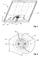
- a flat heating element 1 is made in the form of a glazing unit equipped with a first rigid pane 2, an intermediate layer 3 and a second rigid pane 4.
- the first rigid pane 2 is preferably a thermally prestressed glazing which is provided on its surface facing the intermediate layer 3 of a heating layer 5 configured as electrically conductive coating.
- the heating layer 5 consists of a composition and / or a succession of layers which is suitable for operation as a flat heating layer and which can be thermally stressed sufficiently for prestressing the window.
- Appropriate layer systems have been described many times in the state of the art, so there is no need to go into more detail. They can be made with a high transmission of visible light and therefore in a transparent way.
- Suitable arrangements ensure that said coating 5 is passivated peripherally along the edge of the flat heating element 1, i.e. there is no electrically conductive contact towards its outer or front surface. nor the risk of external corrosive attack on the layered material.
- thermoplastic which forms the intermediate layer 3 for example polyvinyl butyral (PVB) or ethylene vinyl acetate (VA)) a hermetic closure of the edge gap. It is understood that the material of the intermediate layer must be selected from to be well compatible with the material of the coating 5.
- FIG 1 we can see the essential components of the power supply of the heating layer 5, namely first two ribbon-shaped flat electrodes 6 which are arranged on both sides of a separating line 7 which isolates the two poles of the heating layer 5 are vis-a-vis each other.
- the course of the current path between the two electrodes is predetermined by the structural lines formed in the heating layer and is readily apparent from the drawing.
- a junction box 8 provided with a connecting cable 9 (which is only partly represented) is fixed at the location of the electrical contact between the heating layer 5 and the pair of electrodes 6 on the second rigid pane.
- all the devices and electrical interfaces are locally collected at a location of the flat heating element 1.
- the electrodes may naturally have other shapes than those of a ribbon (for example a semicircle).
- structural lines can be started in the area of the heating layer which is covered by the electrodes, so that the electrode is brought into electrical contact with a plurality of current paths electrically connected in parallel.
- Such a configuration or structuring of the heating layer next to its connection area may especially be necessary when the power supply could not be possible near the edge, unlike what has been shown.
- the window 4 which can also be made of glass (possibly prestressed) or synthetic material, has a bore 11 in which a sleeve-shaped lining piece 12 is fixedly inserted. Its outer perimeter is adapted as accurately as possible to the diameter or the perimeter of the bore 11.
- an overhanging flange projection 13 here configured as an annular shoulder, this lining piece 12 clings behind the edge of the liner. 11 in the plane of the intermediate layer 3.
- the free internal space of the lining piece 12 visibly releases the heating layer 5, the two electrodes 6 and the separation line 7.
- the surfaces are represented by fields gray rectangular on which the electrical connection contacts can be placed.
- the liner piece 12 may include shaped members that serve to secure and prevent the connection device from rotating. In this embodiment, they are beaks formed in the wall of its bore and provided with bores in which screws can be screwed. In contrast to the representation, these shaped elements may be arranged unsymmetrically to allow the insertion of other components in the correct position.
- FIG. 3 shows further details of an exemplary structure of the electrical connection device according to the invention, in section, identical parts being provided with another numerical reference than in FIGS. 1 and 2.
- multi-layered structure of the flat heating element Part of the thickness of the rigid pane 2 is represented, and a double line in a chain which passes through the rigid window 4 also indicates that its thickness has been shown shortened. It is obvious that these two rigid panes can be significantly thicker than the intermediate layer 3.
- the electrodes 6 and the junction box 8 which is here only partially represented
- their material has been removed to allow unobstructed access to the electrodes 6. This removal of material must be dimensioned before the binding of the two rigid panes by melting of the intermediate layer 3 so that the adhesive material can not advance to the electrodes.
- the diameter of the bore 11 has been represented smaller with respect to the thickness of the window 4; it is understood that the bore is sized to a width sufficient for the type each time provided connection device.
- connection area An optical masking of the connection area is not necessary for its operation, and fulfills only an aesthetic mission.
- the window 2 and therefore the side of the flat heating element not facing the connecting device will form its visible side.
- an opaque layer 10 between the heating layer 5 and the glass surface to mask this area vis-à-vis the 'outside.
- the actual electrodes can also be used as decorative elements in giving them an optically attractive appearance. We can then do without the opaque layer 10.
- the sleeve-shaped lining piece 12 is fixed in the bore 11 of the second rigid pane 4. Its axial length substantially corresponds to the thickness of the rigid pane 4. (a few millimeters) and it still penetrates in the plane of the intermediate layer 3. Its projection 13 which projects radially outwardly engages behind the edge of the bore 11, so that the piece of trim 12 is maintained in shape correspondence and can not be retrieved.
- this piece of gasket must be inserted into the bore 11 before the two rigid panes 2 and 4 are connected. Only after melting of the thermoplastic intermediate layer 3, it is definitely fixed. In the drawing, it can be seen that the projection 13 is still superimposed on the material of the intermediate layer.
- the lining piece 12 forms the base of the junction box 8.
- Two vertical lines in a chain denote a connection screwed between the two parts.
- a support block 14 is fixed by the connection box 8 in the bore of the packing piece 12, from which two spring contacts 15 extend which extend to the electrodes 6 and which are electrically conductive on them.
- a symbolically indicated temperature sensor 16 is also maintained by means of the contact block 14 and the lining piece 12 in contact with the coated surface of the rigid pane 2. It serves to detect the effective temperature in the contact zone electrodes 6.
- the support block 14 is inserted in the correct position, possibly forced by suitable shaped members in the liner piece 12 so that the spring contacts 15 contact the electrode each time provided, and then immobilized.
- the support block can form a first fixed unit with the connection box 8 and be fixed together with the latter in the trim piece 12.
- the spring contacts 15 satisfy the requirements of a safe and durable electrical connection, if necessary, they could be soldered, in particular thanks to a suitable pre-tinning , the necessary heat can be brought without contact, for example through the coated pane 2.
- the switching symbols of a switch 17 and a transistor 18 represent the electrical or electronic equipment of the support block 14 or of the connection box 8 and may each time represent a plurality of corresponding elements. Other control and switching tasks are also attributed to this area of the connection device in addition to supplying the electrical supply voltage to the electrodes 6 via the connecting cables 9.
- a switching element must evaluate the values measured by the temperature sensor 16 and possibly at least temporarily disconnect the supply of current to the heating layer if the effective temperature should exceed a permissible threshold. However, it is also possible to provide a switching element which provides protection against temperature overruns and which limits, in a manner known per se, the electrical power consumed to permissible values.
- At least one switch that can present a Electronic or electromechanical configuration manages the supply of current to the heating layer.
- This switch can be basically manually and locally connected and be controlled by sensors, for example the temperature sensor 16, or by a remote control device. As already indicated, the latter can form part of an automatic regulation of the temperature of a room (air conditioning installation, etc.) but can also be optionally and basically manually controlled.
- control signals are transmitted wirelessly, a suitable receiver and a decoder and other switching means (eg amplifiers) shall be provided in the junction box 8 or in the support block 14.
- control signals are transmitted by conductors, it will be necessary to provide appropriate evaluation devices for this purpose, in particular in the case where control signals are transmitted by the connecting conductors to the network, anyway present (cable 9), and must be filtered on site.
- the latter can be configured in the form of light signals (light-emitting diodes) and for example be arranged in the region of the separation line 7 between the spring contacts 15 and next to the temperature sensor 16 so as to be visible from the outside of the rigid pane 2. They are also electrically powered via the support block 14 and controlled by said switching elements 17, 18.
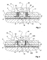
- FIG. 4 shows, in a sectional view corresponding to that of FIG. 3, a variant of a lining piece which is used here in an undercut bore 11 'of the second rigid pane 4. If the same components as in FIG. 2 are represented, the latter receiving the same numerical references and no longer being explained.
- the piece of packing is made in two parts, with a 12D undercut peg and a 12S socket screw. Such undercut sleeves are already known in many applications on glass. The production of bores 11 'undercut or recessed in glass panes is also technically mature.
- the undercut 12D pin may be inserted from the outside into the bore 11 'after completion of the assembly. Then screw the 12S socket screw which can be made of metal or a high-strength synthetic material. Vertical lines along its outer port indicate its self-tapping external thread. When screwing is established the indicated deformation of the undercut peg 12D in a projection 13 'which projects radially in collar. It is seen that this projection fills the undercut chamfer of the bore 11 'in geometric correspondence until its axial extraction becomes impossible. Likewise, the socket screw 12S is immobilized radially and axially in the bore by engagement of its external thread in the ankle.
- the socket screw itself can also be screwed only to a predetermined depth to not come into contact with the electrodes in the bottom of the bore 11 'or damage them or the heating layer 5. It can not further contact the contact springs 15.
- junction box 8 and the socket screw 12S can be assembled into a fixed entity. We could then use the box of the junction box as a lever for screwing the socket screw by hand, the lower side of the junction box which is placed on the upper side of the window 4 at the edge of the bore 11 then forming a depth stop.
- the support block can be fixed in the correct position with the contact springs and possibly the temperature sensor.
- the trim piece While in both Figures 3 and 4, the trim piece is substantially flush with the main surface of the rigid pane 4, the junction box overflows slightly above this surface.
- this side of the flat heating element 1 is most of the time not turned towards the observer / the user in the mounted state, is possibly located facing a wall or is integrated in the latter, the visibility of the connection device on the mask (or optionally on the opaque electrodes configured as decorative elements) remains on the one hand limited, and secondly risks by unauthorized manipulation or inadvertently the connection device are excluded in practice. If there is provided a handle for actuating a control member of the connecting device, the latter will naturally be arranged preferably in easily accessible places, for example near the edge of the flat heating element.
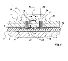
- the embodiment according to FIG. 5 combines a connection device according to the invention with a plate element, in which the functional elements
- the electrical connectors to be connected are on the second rigid pane 4 provided with the bore 11.
- no direct contact is provided here between the spring contacts 15 and the flat electrodes 6 of the heating layer. 5.
- the projection 13 of the lining piece 12 serves instead to keep the connecting bridges 20 in contact with the flat electrodes 6, after the lining piece 12 has been inserted and fixed in the bore 11 of the rigid pane. 4. As the lining piece can be clamped with the junction box 8 and thus the projection 13 is pulled with a preload against the flat electrodes 6, this point of contact is not particularly critical.
- the surfaces of the connecting bridges coming into contact with the planar electrodes may be roughened or provided with tips in order to allow slight penetration of the connection bridges in the planar electrodes.
- connecting bridges 20 opposite the flat electrodes 6 penetrate into the internal space of the lining piece 12. They form at this point, in a manner equivalent to the flat electrodes of the preceding applications, bearing faces for the contacts to spring 15 so that after assembly, they are electrically connected securely via a respective connecting bridge 20 to the respective flat electrodes 6 themselves.
- the connecting bridges 20 are preferably fixedly integrated in the lining piece 12, in order to configure as simply as possible the mounting of the connecting device. This can for example be obtained by overmolding the connecting bridges 20 (thin sheet tapes) with the plastic material of the lining piece 12 during its shaping.
- the separation line 7 is again recognized between the two poles of the heating layer 5 and the opaque layer 10, on which the heating layer is deposited in each case in the contact region.
- another opaque layer 10 is provided on the plane side of the rigid pane 2 located inside the composite, which optically covers the contact region and which can also be made in the form of an element. decorative.
- one or both opaque layers may be omitted, depending on requirements, as they are not significant for the operation of the connecting device or the plate element.
- the adhesive intermediate layer 3 is continuous in the contact region in this illustration, it can also also if necessary also be provided in this variant with a cutout similarly to FIGS. 3 and 4.
- connection device When this connection device is used for electrical functional elements of other types, for example for layered solar cells Thin or impact or precipitation probes, as indicated at the beginning, its basic structure is not modified with respect to that of the exemplary embodiments shown here. By deviating from the drawings, it may possibly provide only one contact or a plurality of contacts in each cut.
Landscapes
- Engineering & Computer Science (AREA)
- General Engineering & Computer Science (AREA)
- Thermal Sciences (AREA)
- Combustion & Propulsion (AREA)
- Mechanical Engineering (AREA)
- Physics & Mathematics (AREA)
- Chemical & Material Sciences (AREA)
- Microelectronics & Electronic Packaging (AREA)
- Surface Heating Bodies (AREA)
- Resistance Heating (AREA)
- Multi-Conductor Connections (AREA)
- Connecting Device With Holders (AREA)
- Coupling Device And Connection With Printed Circuit (AREA)
- Control Of Motors That Do Not Use Commutators (AREA)
- Led Devices (AREA)
Claims (17)
- Mehrschichtiges Flächenheizelement (1) und seine Anschlussvorrichtung, wobei das Flächenelement eine mit einer elektrisch leitfähigen Beschichtung (5) versehene erste starre Scheibe (2) sowie eine mit der ersten starren Scheibe flächig verbundene zweite starre Scheibe (4) umfasst, wobei diese zweite Scheibe mindestens eine Ausnehmung (11; 11') zum Herstellen eines elektrischen Anschlusses zu den elektrisch leitfähigen Beschichtung (5) aufweist, und die Anschlussvorrichtung ein Einsatzteil (12; 12D, 12S) umfasst, das in besagter Ausnehmung (11; 11') mit einem deren Rand in der zwischen den beiden starren Scheiben (2, 4) liegenden Ebene und/ oder einen Hinterschnitt der Ausnehmung hintergreifenden Vorsprung (13; 13') festgelegt ist, wobei das Einsatzteil (12; 12D, 12S) als Widerlager zum Befestigen wenigstens eines elektrisch mit elektrisch leitfähigen Beschichtung (5) verbundenen Anschlussteils (15) dient, dadurch gekennzeichnet, dass das Flächenelement transparent ist, die elektrisch leitende Beschichtung aus einer transparenten Heizschicht besteht und am Umfang des Flächenelements passiviert ist, wobei diese Heizschicht als elektrische Zuleitung zwei Bereiche mit unterschiedlicher Polarität auf, die in den Bereich der Ausnehmung (11; 11') eingeführt werden und aus zwei flachen, streifenförmigen Elektroden (6) bestehen, die auf beiden Seiten einer die beiden Bereiche voneinander isolierenden Trennungslinie (7) angeordnet sind, und dadurch, dass jeder dieser Bereiche mit einem am Einsatzteil befestigten Anschlusselement (15) elektrisch verbunden ist.
- Flächenelement und seine Anschlussvorrichtung nach Anspruch 1, dadurch gekennzeichnet, dass die Ausnehmung (11) in der mit der Heizschicht versehenen starren Scheibe oder in der anderen starren Scheibe vorgesehen ist.
- Flächenelement und seine Anschlussvorrichtung nach Anspruch 1 oder 2, dadurch gekennzeichnet, dass jedes Anschlussteil mindestens einen mit der Heizschicht elektrisch kontaktierten Federkontakt (15) umfasst.
- Flächenelement und seine Anschlussvorrichtung nach einem der vorstehenden Ansprüche, dadurch gekennzeichnet, dass das Einsatzteil (12) hülsenförmig ausgebildet und in die Ausnehmung (11) eingesetzt ist, wobei sein Vorsprung (13) den Rand der Ausnehmung in der Ebene der Zwischenschicht (3) hintergreift.
- Flächenelement und seine Anschlussvorrichtung nach Anspruch 1, dadurch gekennzeichnet, dass der Vorsprung (13) des Einsatzteils (12) mit mindestens einem Kontaktmittel (20) versehen ist, das zum Herstellen einer elektrischen Verbindung zwischen mindestens einem Anschlussteil (15) und der Heizschicht vorgesehen ist.
- Flächenelement und seine Anschlussvorrichtung nach Anspruch 5, dadurch gekennzeichnet, dass ein Kontaktmittel als Anschlussbrücke (20) ausgeführt ist, welche im Innenraum des hülsenförmigen Einsatzteils (12) eine Kontaktfläche für ein Anschlussteil (15) und auf einer Fläche des Vorsprungs (13) eine Kontaktfläche zum Verbinden mit der Heizschicht aufweist.
- Flächenelement und seine Anschlussvorrichtung nach einem der vorstehenden Ansprüche, dadurch gekennzeichnet, dass das Einsatzteil einen Dübel, insbesondere einen Hinterschnittdübel (12D) umfasst, der mithilfe einer Schraube (12S) in der Ausnehmung (11') festgelegt ist.
- Flächenelement und seine Anschlussvorrichtung nach Anspruch 7, dadurch gekennzeichnet, dass die Schraube als Hülsenschraube (12S) mit Außengewinde ausgeführt ist, deren Innenraum eine Aufnahme für weitere Bauteile der Anschlussvorrichtung bildet.
- Flächenelement und seine Anschlussvorrichtung nach einem der vorstehenden Ansprüche, dadurch gekennzeichnet, dass sie mit Mitteln zum Befestigen oder Aufhängen des Flächenelements an einer Unterkonstruktion, insbesondere an einer Gebäudewand, versehen ist.
- Flächenelement und seine Anschlussvorrichtung nach Anspruch 7, gekennzeichnet durch mindestens einen Temperaturfühler (16) zum Erfassen der Ist-Temperatur der Heizschicht (5).
- Flächenelement und seine Anschlussvorrichtung nach Anspruch 10, gekennzeichnet durch ein vom Temperaturfühler (16) steuerbares Schaltelement (17, 18) zum Unterbrechen oder Reduzieren des Heizstroms bei Überschreiten einer vorgegebenen Temperaturschwelle.
- Flächenelement und seine Anschlussvorrichtung nach einem der vorstehenden Ansprüche, gekennzeichnet durch einen manuell betätigbaren Einsteller zum Vorgeben einer Temperaturschwelle der Heizschicht.
- Flächenelement und seine Anschlussvorrichtung nach einem der vorstehenden Ansprüche, gekennzeichnet durch einen Empfänger für kontaktlos übertragbare Steuersignale und durch eine von dem Empfänger steuerbare Schalteinrichtung (17, 18) zum fernsteuerbaren Ein- und Ausschalten der Heizschicht.
- Flächenelement und seine Anschlussvorrichtung nach einem der vorstehenden Ansprüche, gekennzeichnet durch mindestens ein Anzeigeelement, insbesondere ein Lichtsignal, für den Betriebszustand der Heizschicht.
- Flächenelement und seine Anschlussvorrichtung nach einem der vorstehenden Ansprüche, gekennzeichnet durch eine Anschlussdose (8) in Gehäuseform als Abdeckung nach außen.
- Flächenelement und seine Anschlussvorrichtung nach einem der vorstehenden Ansprüche, dadurch gekennzeichnet, dass dessen eine starre Platte eine Glasscheibe (2) ist.
- Flächenelement und seine Anschlussvorrichtung nach einem der vorstehenden Ansprüche, dadurch gekennzeichnet, dass mindestens im Bereich der Ausnehmung oder der Anschlussvorrichtung auf der von der Ausnehmung abgewandten Seite eine optische Kaschierung vorgesehen ist.
Applications Claiming Priority (5)
| Application Number | Priority Date | Filing Date | Title |
|---|---|---|---|
| DE10241728A DE10241728B4 (de) | 2002-09-10 | 2002-09-10 | Mehrschichtiges elektrisches beheizbares Flächenelement |
| DE10241728 | 2002-09-10 | ||
| DE20308376U | 2003-05-28 | ||
| DE20308376U DE20308376U1 (de) | 2002-09-10 | 2003-05-28 | Anschlussvorrichtung für ein mehrschichtiges, mit elektrischen Funktionselementen bestücktes Flächenelement und Flächenelement |
| PCT/FR2003/002651 WO2004025995A2 (fr) | 2002-09-10 | 2003-09-05 | Dispositif de raccordement pour un element plat en plusieurs couches equipe d'elements fonctionnels electriques et element plat |
Publications (2)
| Publication Number | Publication Date |
|---|---|
| EP1537762A2 EP1537762A2 (de) | 2005-06-08 |
| EP1537762B1 true EP1537762B1 (de) | 2006-04-05 |
Family
ID=31995054
Family Applications (1)
| Application Number | Title | Priority Date | Filing Date |
|---|---|---|---|
| EP03769575A Expired - Lifetime EP1537762B1 (de) | 2002-09-10 | 2003-09-05 | Verbindungseinrichtung für ein flächiges element mit mehreren schichten ausgestattet mit elektrischen funktionselementen und flächiges element |
Country Status (9)
| Country | Link |
|---|---|
| US (1) | US7156666B2 (de) |
| EP (1) | EP1537762B1 (de) |
| KR (1) | KR101061233B1 (de) |
| AT (1) | ATE322802T1 (de) |
| AU (1) | AU2003278267A1 (de) |
| DE (1) | DE60304485T2 (de) |
| ES (1) | ES2261981T3 (de) |
| PT (1) | PT1537762E (de) |
| WO (1) | WO2004025995A2 (de) |
Families Citing this family (29)
| Publication number | Priority date | Publication date | Assignee | Title |
|---|---|---|---|---|
| DE102004025627A1 (de) * | 2004-05-25 | 2005-12-22 | Tyco Electronics Amp Gmbh | Solarmodul mit Anschlusselement |
| US20060235717A1 (en) * | 2005-04-18 | 2006-10-19 | Solaria Corporation | Method and system for manufacturing solar panels using an integrated solar cell using a plurality of photovoltaic regions |
| US20060283495A1 (en) * | 2005-06-06 | 2006-12-21 | Solaria Corporation | Method and system for integrated solar cell using a plurality of photovoltaic regions |
| US20080178922A1 (en) * | 2005-07-26 | 2008-07-31 | Solaria Corporation | Method and system for manufacturing solar panels using an integrated solar cell using a plurality of photovoltaic regions |
| US7910822B1 (en) | 2005-10-17 | 2011-03-22 | Solaria Corporation | Fabrication process for photovoltaic cell |
| US8227688B1 (en) | 2005-10-17 | 2012-07-24 | Solaria Corporation | Method and resulting structure for assembling photovoltaic regions onto lead frame members for integration on concentrating elements for solar cells |
| DE202005020315U1 (de) * | 2005-12-15 | 2006-02-16 | Döppner Bauelemente GmbH & Co. KG | Elektrischer Sockelanschluss |
| CA2533859A1 (fr) * | 2006-01-25 | 2007-07-25 | Prelco Inc. | Systeme d'attache pour gaine protectrice de cable electrique d'alimentation des vitrages |
| US20070194216A1 (en) * | 2006-02-21 | 2007-08-23 | Exatec, Llc | Printable controls for a window assembly |
| US20090056806A1 (en) * | 2007-09-05 | 2009-03-05 | Solaria Corporation | Solar cell structure including a plurality of concentrator elements with a notch design and predetermined radii and method |
| US7910392B2 (en) | 2007-04-02 | 2011-03-22 | Solaria Corporation | Method and system for assembling a solar cell package |
| US7495487B2 (en) * | 2007-04-09 | 2009-02-24 | Micron Technology, Inc. | Delay-locked loop (DLL) system for determining forward clock path delay |
| US8119902B2 (en) * | 2007-05-21 | 2012-02-21 | Solaria Corporation | Concentrating module and method of manufacture for photovoltaic strips |
| US7419377B1 (en) * | 2007-08-20 | 2008-09-02 | Solaria Corporation | Electrical coupling device and method for solar cells |
| US7910035B2 (en) * | 2007-12-12 | 2011-03-22 | Solaria Corporation | Method and system for manufacturing integrated molded concentrator photovoltaic device |
| US20100065105A1 (en) * | 2008-09-12 | 2010-03-18 | Francois Andre Koran | Thin Film Photovoltaic Module Having a Contoured Substrate |
| TW201012010A (en) * | 2008-09-15 | 2010-03-16 | Wistron Neweb Corp | Female adapter for a connector |
| US8124868B2 (en) | 2008-12-16 | 2012-02-28 | Solutia Inc. | Thin film photovoltaic module with contoured deairing substrate |
| DE102009016686A1 (de) * | 2009-04-07 | 2009-10-29 | Daimler Ag | Scheibe eines Kraftwagens |
| USD699176S1 (en) | 2011-06-02 | 2014-02-11 | Solaria Corporation | Fastener for solar modules |
| BE1020124A3 (fr) * | 2011-07-20 | 2013-05-07 | Agc Glass Europe | Panneau de vitrage isolant comprenant au moins un espace interne comprenant un lame d'un gaz isolant. |
| ITVI20120093A1 (it) * | 2012-04-23 | 2013-10-24 | Laborvetro Di Antonello Marano | Un gruppo di riscaldamento di ambienti |
| US9829202B2 (en) * | 2012-09-11 | 2017-11-28 | University of Alaska Anchorage | Systems and methods for heating concrete structures |
| WO2015056582A1 (ja) | 2013-10-16 | 2015-04-23 | 旭硝子株式会社 | 給電構造及びそれを備えた窓用樹脂製板状体、並びに給電構造を備えた窓用樹脂製板状体の製造方法 |
| US10149349B2 (en) * | 2014-06-09 | 2018-12-04 | Mitsuko BABA | Heat generating body |
| US10562274B1 (en) | 2016-02-22 | 2020-02-18 | Apple Inc. | Glass fastening and sealing systems |
| WO2018215317A1 (de) * | 2017-05-24 | 2018-11-29 | Saint-Gobain Glass France | Scheibenanordnung mit elektrischem verbinder |
| EP4190125A1 (de) * | 2020-07-29 | 2023-06-07 | Carlex Glass America, LLC | Glasprodukt, verbinder und verfahren zur installation des verbinders |
| EP4043255B1 (de) * | 2021-02-11 | 2024-11-27 | Inalfa Roof Systems Group B.V. | Transparente dachplatte mit isolierter zentraleinheit |
Family Cites Families (15)
| Publication number | Priority date | Publication date | Assignee | Title |
|---|---|---|---|---|
| US2982934A (en) * | 1956-08-27 | 1961-05-02 | Libbey Owens Ford Glass Co | Electrically conducting glass unit |
| FR1488875A (fr) | 1965-08-12 | 1967-07-13 | Ritter Pfaudler Corp | Dispositif électrique et procédé pour sa fabrication |
| JPS5060513A (de) * | 1973-09-28 | 1975-05-24 | ||
| DE7801989U1 (de) | 1978-01-24 | 1979-07-05 | Schock & Co Gmbh, 7060 Schorndorf | Beheizbarer spiegel |
| JPS62249383A (ja) | 1986-04-22 | 1987-10-30 | 日立電線株式会社 | 面状発熱体 |
| FR2646968B1 (fr) * | 1989-05-12 | 1991-08-30 | Boyeldieu Andre | Dispositif de connexion pour circuit de chauffage et de desembuage d'une glace |
| FR2652980B1 (fr) * | 1989-10-06 | 1996-07-12 | Nicolitch | Feuille de chauffage electrique et procede de fabrication d'une telle feuille. |
| US5106308A (en) * | 1991-03-04 | 1992-04-21 | Allied-Signal Inc. | Planar contact grid array connector |
| DE4325024C2 (de) | 1993-07-26 | 1995-09-07 | Ver Glaswerke Gmbh | Befestigungselement für ein aus einer Verbundglasscheibe bestehendes Glasbauelement an einer Trägerkonstruktion |
| DE69413679T2 (de) * | 1994-07-15 | 1999-04-29 | Berg Electronics Manufacturing B.V., S'-Hertogenbosch | Zusammenbau eines abgeschirmten Verbinders und einer Leiterplatte mit kontaktierten Löchern |
| JPH1022065A (ja) | 1996-07-04 | 1998-01-23 | Nec Eng Ltd | シートヒータ |
| US6188028B1 (en) * | 1997-06-09 | 2001-02-13 | Tessera, Inc. | Multilayer structure with interlocking protrusions |
| DE29718843U1 (de) | 1997-10-23 | 1997-12-11 | Feltl, Richard, 75438 Knittlingen | Beheizbares Aquarium oder Terrarium |
| US6466447B2 (en) * | 2000-02-24 | 2002-10-15 | Denso Corporation | Electronic control unit having flexible wires connecting connector to circuit board |
| US6511347B2 (en) * | 2001-06-28 | 2003-01-28 | International Business Machines Corporation | Terminating floating signals on a BGA module to a ground plane on a ball grid array (BGA) circuit board site |
-
2003
- 2003-09-05 KR KR1020057004129A patent/KR101061233B1/ko not_active Expired - Fee Related
- 2003-09-05 AT AT03769575T patent/ATE322802T1/de active
- 2003-09-05 PT PT03769575T patent/PT1537762E/pt unknown
- 2003-09-05 ES ES03769575T patent/ES2261981T3/es not_active Expired - Lifetime
- 2003-09-05 AU AU2003278267A patent/AU2003278267A1/en not_active Abandoned
- 2003-09-05 DE DE60304485T patent/DE60304485T2/de not_active Expired - Lifetime
- 2003-09-05 EP EP03769575A patent/EP1537762B1/de not_active Expired - Lifetime
- 2003-09-05 WO PCT/FR2003/002651 patent/WO2004025995A2/fr not_active Ceased
- 2003-09-05 US US10/526,764 patent/US7156666B2/en not_active Expired - Fee Related
Also Published As
| Publication number | Publication date |
|---|---|
| KR101061233B1 (ko) | 2011-09-05 |
| ATE322802T1 (de) | 2006-04-15 |
| DE60304485T2 (de) | 2006-10-12 |
| WO2004025995A2 (fr) | 2004-03-25 |
| EP1537762A2 (de) | 2005-06-08 |
| AU2003278267A1 (en) | 2004-04-30 |
| KR20050047110A (ko) | 2005-05-19 |
| US7156666B2 (en) | 2007-01-02 |
| WO2004025995A3 (fr) | 2004-04-22 |
| US20060099833A1 (en) | 2006-05-11 |
| PT1537762E (pt) | 2006-08-31 |
| DE60304485D1 (de) | 2006-05-18 |
| ES2261981T3 (es) | 2006-11-16 |
Similar Documents
| Publication | Publication Date | Title |
|---|---|---|
| EP1537762B1 (de) | Verbindungseinrichtung für ein flächiges element mit mehreren schichten ausgestattet mit elektrischen funktionselementen und flächiges element | |
| EP1478291B1 (de) | Plattenelement mit beheizter fläche | |
| EP1627555B1 (de) | Mit einer geheizten schicht ausgestattetes laminiertes element | |
| EP1714185B1 (de) | Verfahren zur steuerung eines elements, das elektrochromisch innerhalb eines transparenten fensters angesteuert werden kann | |
| CA2670954C (fr) | Vitre feuilletee avec un dispositif de fixation introduit dans un orifice de passage pour des objets | |
| EP1459602B1 (de) | Laminierte glasscheibe mit elektrisch gesteuertem funktionalelement | |
| EP1559296B1 (de) | Transparentes fenster mit nichttransparenter kontaktfläche für l t-bond-verbindung | |
| EP2010384A1 (de) | Schichtverglasung und dichtung sowie umfangsverstärkungselemente dafür | |
| FR2921520A1 (fr) | Element de connexion electrique et vitrage pourvu d'un tel element | |
| CA3025135A1 (fr) | Toit vitre feuillete lumineux de vehicule, vehicule l'incorporant et fabrication | |
| EP1585635A2 (de) | Verglasung mit elektronischen elementen | |
| EP1964450A1 (de) | Beleuchtungsstruktur mit mindestens einer leuchtdiode, herstellungs- und benutzungsverfahren dafür | |
| EP0177420B1 (de) | Windschutzscheibe aus Verbundglas mit eingebauter Fotozelle und automatischer Steuerung der Beleuchtung eines Fahrzeugs | |
| EP1106771B1 (de) | Bauelement mit einer Kabeldurchführung sowie Herstellungsverfahren für dasselbe | |
| EP1629697A1 (de) | Plattenelement für geschichtete erwärmung | |
| FR2931308A1 (fr) | Dispositif de connexion electrique d'un vitrage feuillete a un equipement hors vitrage, procede d'assemblage d'un vitrage dote d'un tel dispositif de connexion, et vitrage ainsi obtenu | |
| EP1004223A1 (de) | Elektrisches heizungspaneel | |
| FR3054403B1 (fr) | Vitrage avec element electriquement conducteur et sa connexion electrique | |
| EP3242537B1 (de) | Paneel, das eine elektronische komponente umfasst | |
| EP3723982A1 (de) | Aus einem strukturellen kunststoffmaterial hergestellte heizverglasung | |
| EP2198106A1 (de) | Verglasungselement mit stromleitstruktur |
Legal Events
| Date | Code | Title | Description |
|---|---|---|---|
| PUAI | Public reference made under article 153(3) epc to a published international application that has entered the european phase |
Free format text: ORIGINAL CODE: 0009012 |
|
| 17P | Request for examination filed |
Effective date: 20050309 |
|
| AK | Designated contracting states |
Kind code of ref document: A2 Designated state(s): AT BE BG CH CY CZ DE DK EE ES FI FR GB GR HU IE IT LI LU MC NL PT RO SE SI SK TR |
|
| AX | Request for extension of the european patent |
Extension state: AL LT LV MK |
|
| GRAP | Despatch of communication of intention to grant a patent |
Free format text: ORIGINAL CODE: EPIDOSNIGR1 |
|
| DAX | Request for extension of the european patent (deleted) | ||
| GRAS | Grant fee paid |
Free format text: ORIGINAL CODE: EPIDOSNIGR3 |
|
| GRAA | (expected) grant |
Free format text: ORIGINAL CODE: 0009210 |
|
| AK | Designated contracting states |
Kind code of ref document: B1 Designated state(s): AT BE BG CH CY CZ DE DK EE ES FI FR GB GR HU IE IT LI LU MC NL PT RO SE SI SK TR |
|
| PG25 | Lapsed in a contracting state [announced via postgrant information from national office to epo] |
Ref country code: SK Free format text: LAPSE BECAUSE OF FAILURE TO SUBMIT A TRANSLATION OF THE DESCRIPTION OR TO PAY THE FEE WITHIN THE PRESCRIBED TIME-LIMIT Effective date: 20060405 Ref country code: SI Free format text: LAPSE BECAUSE OF FAILURE TO SUBMIT A TRANSLATION OF THE DESCRIPTION OR TO PAY THE FEE WITHIN THE PRESCRIBED TIME-LIMIT Effective date: 20060405 Ref country code: IE Free format text: LAPSE BECAUSE OF FAILURE TO SUBMIT A TRANSLATION OF THE DESCRIPTION OR TO PAY THE FEE WITHIN THE PRESCRIBED TIME-LIMIT Effective date: 20060405 Ref country code: FI Free format text: LAPSE BECAUSE OF FAILURE TO SUBMIT A TRANSLATION OF THE DESCRIPTION OR TO PAY THE FEE WITHIN THE PRESCRIBED TIME-LIMIT Effective date: 20060405 |
|
| REG | Reference to a national code |
Ref country code: GB Ref legal event code: FG4D Free format text: NOT ENGLISH |
|
| REG | Reference to a national code |
Ref country code: CH Ref legal event code: EP |
|
| REG | Reference to a national code |
Ref country code: IE Ref legal event code: FG4D Free format text: LANGUAGE OF EP DOCUMENT: FRENCH |
|
| REF | Corresponds to: |
Ref document number: 60304485 Country of ref document: DE Date of ref document: 20060518 Kind code of ref document: P |
|
| PG25 | Lapsed in a contracting state [announced via postgrant information from national office to epo] |
Ref country code: DK Free format text: LAPSE BECAUSE OF FAILURE TO SUBMIT A TRANSLATION OF THE DESCRIPTION OR TO PAY THE FEE WITHIN THE PRESCRIBED TIME-LIMIT Effective date: 20060705 |
|
| REG | Reference to a national code |
Ref country code: SE Ref legal event code: TRGR |
|
| GBT | Gb: translation of ep patent filed (gb section 77(6)(a)/1977) |
Effective date: 20060621 |
|
| REG | Reference to a national code |
Ref country code: PT Ref legal event code: SC4A Effective date: 20060630 |
|
| REG | Reference to a national code |
Ref country code: RO Ref legal event code: EPE |
|
| PG25 | Lapsed in a contracting state [announced via postgrant information from national office to epo] |
Ref country code: MC Free format text: LAPSE BECAUSE OF NON-PAYMENT OF DUE FEES Effective date: 20060930 |
|
| REG | Reference to a national code |
Ref country code: IE Ref legal event code: FD4D |
|
| REG | Reference to a national code |
Ref country code: ES Ref legal event code: FG2A Ref document number: 2261981 Country of ref document: ES Kind code of ref document: T3 |
|
| REG | Reference to a national code |
Ref country code: HU Ref legal event code: AG4A Ref document number: E000726 Country of ref document: HU |
|
| PLBE | No opposition filed within time limit |
Free format text: ORIGINAL CODE: 0009261 |
|
| STAA | Information on the status of an ep patent application or granted ep patent |
Free format text: STATUS: NO OPPOSITION FILED WITHIN TIME LIMIT |
|
| 26N | No opposition filed |
Effective date: 20070108 |
|
| PG25 | Lapsed in a contracting state [announced via postgrant information from national office to epo] |
Ref country code: GR Free format text: LAPSE BECAUSE OF FAILURE TO SUBMIT A TRANSLATION OF THE DESCRIPTION OR TO PAY THE FEE WITHIN THE PRESCRIBED TIME-LIMIT Effective date: 20060706 |
|
| REG | Reference to a national code |
Ref country code: CH Ref legal event code: PL |
|
| PG25 | Lapsed in a contracting state [announced via postgrant information from national office to epo] |
Ref country code: EE Free format text: LAPSE BECAUSE OF FAILURE TO SUBMIT A TRANSLATION OF THE DESCRIPTION OR TO PAY THE FEE WITHIN THE PRESCRIBED TIME-LIMIT Effective date: 20060405 Ref country code: BG Free format text: LAPSE BECAUSE OF FAILURE TO SUBMIT A TRANSLATION OF THE DESCRIPTION OR TO PAY THE FEE WITHIN THE PRESCRIBED TIME-LIMIT Effective date: 20060705 |
|
| PG25 | Lapsed in a contracting state [announced via postgrant information from national office to epo] |
Ref country code: LI Free format text: LAPSE BECAUSE OF NON-PAYMENT OF DUE FEES Effective date: 20070930 Ref country code: CH Free format text: LAPSE BECAUSE OF NON-PAYMENT OF DUE FEES Effective date: 20070930 |
|
| PG25 | Lapsed in a contracting state [announced via postgrant information from national office to epo] |
Ref country code: CY Free format text: LAPSE BECAUSE OF FAILURE TO SUBMIT A TRANSLATION OF THE DESCRIPTION OR TO PAY THE FEE WITHIN THE PRESCRIBED TIME-LIMIT Effective date: 20060405 |
|
| PG25 | Lapsed in a contracting state [announced via postgrant information from national office to epo] |
Ref country code: LU Free format text: LAPSE BECAUSE OF NON-PAYMENT OF DUE FEES Effective date: 20140905 |
|
| REG | Reference to a national code |
Ref country code: FR Ref legal event code: PLFP Year of fee payment: 14 |
|
| REG | Reference to a national code |
Ref country code: FR Ref legal event code: PLFP Year of fee payment: 15 |
|
| REG | Reference to a national code |
Ref country code: FR Ref legal event code: PLFP Year of fee payment: 16 |
|
| PG25 | Lapsed in a contracting state [announced via postgrant information from national office to epo] |
Ref country code: LU Free format text: LAPSE BECAUSE OF NON-PAYMENT OF DUE FEES Effective date: 20140905 |
|
| PGRI | Patent reinstated in contracting state [announced from national office to epo] |
Ref country code: LU Effective date: 20150817 |
|
| PGFP | Annual fee paid to national office [announced via postgrant information from national office to epo] |
Ref country code: NL Payment date: 20220819 Year of fee payment: 20 |
|
| PGFP | Annual fee paid to national office [announced via postgrant information from national office to epo] |
Ref country code: TR Payment date: 20220902 Year of fee payment: 20 Ref country code: SE Payment date: 20220811 Year of fee payment: 20 Ref country code: RO Payment date: 20220829 Year of fee payment: 20 Ref country code: PT Payment date: 20220902 Year of fee payment: 20 Ref country code: LU Payment date: 20220826 Year of fee payment: 20 Ref country code: IT Payment date: 20220811 Year of fee payment: 20 Ref country code: GB Payment date: 20220804 Year of fee payment: 20 Ref country code: DE Payment date: 20220621 Year of fee payment: 20 Ref country code: CZ Payment date: 20220818 Year of fee payment: 20 Ref country code: AT Payment date: 20220825 Year of fee payment: 20 |
|
| PGFP | Annual fee paid to national office [announced via postgrant information from national office to epo] |
Ref country code: HU Payment date: 20220816 Year of fee payment: 20 Ref country code: FR Payment date: 20220930 Year of fee payment: 20 Ref country code: BE Payment date: 20220819 Year of fee payment: 20 |
|
| PGFP | Annual fee paid to national office [announced via postgrant information from national office to epo] |
Ref country code: ES Payment date: 20221005 Year of fee payment: 20 |
|
| REG | Reference to a national code |
Ref country code: DE Ref legal event code: R071 Ref document number: 60304485 Country of ref document: DE |
|
| REG | Reference to a national code |
Ref country code: NL Ref legal event code: MK Effective date: 20230904 |
|
| REG | Reference to a national code |
Ref country code: ES Ref legal event code: FD2A Effective date: 20230926 |
|
| REG | Reference to a national code |
Ref country code: GB Ref legal event code: PE20 Expiry date: 20230904 |
|
| REG | Reference to a national code |
Ref country code: BE Ref legal event code: MK Effective date: 20230905 |
|
| REG | Reference to a national code |
Ref country code: AT Ref legal event code: MK07 Ref document number: 322802 Country of ref document: AT Kind code of ref document: T Effective date: 20230905 |
|
| PG25 | Lapsed in a contracting state [announced via postgrant information from national office to epo] |
Ref country code: PT Free format text: LAPSE BECAUSE OF EXPIRATION OF PROTECTION Effective date: 20230914 Ref country code: GB Free format text: LAPSE BECAUSE OF EXPIRATION OF PROTECTION Effective date: 20230904 Ref country code: ES Free format text: LAPSE BECAUSE OF EXPIRATION OF PROTECTION Effective date: 20230906 Ref country code: CZ Free format text: LAPSE BECAUSE OF EXPIRATION OF PROTECTION Effective date: 20230905 |
|
| REG | Reference to a national code |
Ref country code: SE Ref legal event code: EUG |