EP1627320B1 - Compartiment de distribution securise et procedes - Google Patents
Compartiment de distribution securise et procedes Download PDFInfo
- Publication number
- EP1627320B1 EP1627320B1 EP04751552.3A EP04751552A EP1627320B1 EP 1627320 B1 EP1627320 B1 EP 1627320B1 EP 04751552 A EP04751552 A EP 04751552A EP 1627320 B1 EP1627320 B1 EP 1627320B1
- Authority
- EP
- European Patent Office
- Prior art keywords
- dispensing
- computer
- dispenser
- frame
- mechanisms
- Prior art date
- Legal status (The legal status is an assumption and is not a legal conclusion. Google has not performed a legal analysis and makes no representation as to the accuracy of the status listed.)
- Expired - Lifetime
Links
- 238000000034 method Methods 0.000 title claims description 34
- 230000007246 mechanism Effects 0.000 claims description 224
- 230000000007 visual effect Effects 0.000 claims description 8
- 238000003825 pressing Methods 0.000 claims description 4
- 230000008878 coupling Effects 0.000 claims 1
- 238000010168 coupling process Methods 0.000 claims 1
- 238000005859 coupling reaction Methods 0.000 claims 1
- 239000003814 drug Substances 0.000 description 16
- 230000008569 process Effects 0.000 description 13
- 238000004891 communication Methods 0.000 description 7
- 229940079593 drug Drugs 0.000 description 7
- 239000006187 pill Substances 0.000 description 4
- 239000007787 solid Substances 0.000 description 3
- 238000010276 construction Methods 0.000 description 2
- 238000002483 medication Methods 0.000 description 2
- 238000012986 modification Methods 0.000 description 2
- 230000004048 modification Effects 0.000 description 2
- 238000002360 preparation method Methods 0.000 description 2
- 239000003708 ampul Substances 0.000 description 1
- 230000009286 beneficial effect Effects 0.000 description 1
- 230000008859 change Effects 0.000 description 1
- 238000012790 confirmation Methods 0.000 description 1
- 238000006073 displacement reaction Methods 0.000 description 1
- 230000000694 effects Effects 0.000 description 1
- 230000006870 function Effects 0.000 description 1
- 238000012423 maintenance Methods 0.000 description 1
- 238000012856 packing Methods 0.000 description 1
- 230000008439 repair process Effects 0.000 description 1
- 238000013515 script Methods 0.000 description 1
- 238000012795 verification Methods 0.000 description 1
Images


Classifications
-
- G—PHYSICS
- G07—CHECKING-DEVICES
- G07F—COIN-FREED OR LIKE APPARATUS
- G07F11/00—Coin-freed apparatus for dispensing, or the like, discrete articles
- G07F11/62—Coin-freed apparatus for dispensing, or the like, discrete articles in which the articles are stored in compartments in fixed receptacles
-
- G—PHYSICS
- G07—CHECKING-DEVICES
- G07F—COIN-FREED OR LIKE APPARATUS
- G07F11/00—Coin-freed apparatus for dispensing, or the like, discrete articles
- G07F11/46—Coin-freed apparatus for dispensing, or the like, discrete articles from movable storage containers or supports
- G07F11/60—Coin-freed apparatus for dispensing, or the like, discrete articles from movable storage containers or supports the storage containers or supports being rectilinearly movable
-
- G—PHYSICS
- G07—CHECKING-DEVICES
- G07F—COIN-FREED OR LIKE APPARATUS
- G07F17/00—Coin-freed apparatus for hiring articles; Coin-freed facilities or services
- G07F17/0092—Coin-freed apparatus for hiring articles; Coin-freed facilities or services for assembling and dispensing of pharmaceutical articles
-
- G—PHYSICS
- G16—INFORMATION AND COMMUNICATION TECHNOLOGY [ICT] SPECIALLY ADAPTED FOR SPECIFIC APPLICATION FIELDS
- G16H—HEALTHCARE INFORMATICS, i.e. INFORMATION AND COMMUNICATION TECHNOLOGY [ICT] SPECIALLY ADAPTED FOR THE HANDLING OR PROCESSING OF MEDICAL OR HEALTHCARE DATA
- G16H20/00—ICT specially adapted for therapies or health-improving plans, e.g. for handling prescriptions, for steering therapy or for monitoring patient compliance
- G16H20/10—ICT specially adapted for therapies or health-improving plans, e.g. for handling prescriptions, for steering therapy or for monitoring patient compliance relating to drugs or medications, e.g. for ensuring correct administration to patients
- G16H20/13—ICT specially adapted for therapies or health-improving plans, e.g. for handling prescriptions, for steering therapy or for monitoring patient compliance relating to drugs or medications, e.g. for ensuring correct administration to patients delivered from dispensers
Definitions
- This invention relates generally to the field of dispensing and restocking items, and in particular to the dispensing and restocking of secured items, such as, but not limited to, pharmaceuticals. More specifically, the invention relates to dispensing devices and methods for dispensing a wide range of items upon request.
- a medicine packing apparatus in which a medicine container corresponding to a prescription is taken from medicine storage shelves to set on a medicine feeder mechanism, which enables the medicine container to be readily searched and identified.
- US 2001/029405 A1 is an apparatus for dispensing items from a dispensing unit.
- the dispensing unit comprises a plurality of locations in which the items are held, a processor in which records corresponding to the items on the unit are stored, and a plurality of item switches corresponding to the locations in which the items are held.
- the item switches are connected to the processor so that a user of the dispensing unit can input records of items removed from the unit into the processor.
- US 4 225 056 A is a computerized vending machine which has a supporting frame wherein a plurality of product dispensing trays is housed. Each product dispensing tray has a product dispensing mechanism including a special arrangement, i.e. a solenoid and a product dispenser capable of limit rotary motion under the control of the solenoid.
- a product dispensing mechanism including a special arrangement, i.e. a solenoid and a product dispenser capable of limit rotary motion under the control of the solenoid.
- US 5 912 818 A is a system for tracking and dispensing medical items.
- EP 1 241 617 A is a medicine feeder apparatus.
- EP 1 053 738 A2 is a solid preparation filling apparatus for filling a solid preparation designated by a prescription in a hospital and the like.
- a dispensing device comprises a cabinet having a front, a back and a pair of sides that enclose an interior storage area.
- a dispenser frame is coupled to the cabinet and, in some cases, may be configured to be pulled out from the interior.
- the dispenser frame includes one or more dividers to which may be coupled one or more dispensing mechanisms that hold items to be dispensed.
- a lockable door may be coupled to the front of the cabinet so as to be positioned in front of the dispenser frame. Hence, by opening the door access to the dispenser frame is gained.
- a dispense drawer may also be coupled to the cabinet below the storage dispenser frame. In this way, items dispensed from the dispensing mechanisms may fall into the dispense drawer.
- the dividers may be reconfigurable so that different types and/or arrangements of dispensing mechanisms may be provided in the same dispenser frame.
- the dispense drawer may have approximately the same width as the dispenser frame.
- the dispenser frame and dispense drawer may extend across the front of the cabinet. In this way, a single dispenser frame holding essentially all of the cabinet's dispensing mechanisms may be accessed by simply pulling out the dispenser frame.
- multiple dispense drawers could also be provided.
- the dispensing cabinet may also have a computer system that is employed to store information, such as patient information, nurse user information, restock user or pharmacist information, item information, and the like.
- the computer system may also be used to facilitate operation of the dispensing cabinet, such as by controlling dispensing operations, restocking operations, and the like.
- the computer system may include various controllers, circuit boards, other circuitry or the like to determine the divider configuration, as well as to determine the addresses of the dispensing mechanisms and to control their operation.
- the computer system may include a circuit board that is mounted to the dispenser frame and a controller that is mounted to the cabinet frame.
- the computer system may also be used to sense the configuration of the dividers. For example, in one aspect, the computer system may be used to poll as to whether a divider is present at a particular location on the dispenser frame. This information may then be stored in the computer's memory.
- each dispensing mechanism on a particular divider may also be sensed and sent to the computer so that items for each dispensing unit may be assigned and stored in the computer.
- the dividers may include interfaces for interfacing with the dispensing mechanisms.
- a sensing mechanism such as a button or a switch, on the dispensing unit may be actuated to create a detectable event, such as a short in a circuit.
- the location of the divider may be determined and transmitted to the computer.
- Information on the item may then be input into the computer so that the computer will have a record of the address for each dispensing mechanism and its associated item.
- restock user identification information may be input into the computer along with a request to restock items.
- a restock list may be generated by the computer and selected by the restock user or pharmacist. This list may be transmitted from a host over a computer network.
- a light on the door may light and a button on the door may be pushed to open the door, although in some cases the door may automatically open so that pressing of a button is not needed.
- the dispenser frame may then be pulled from the cabinet to gain access to the dispensing mechanisms. However, in some cases, the dispensing mechanisms may be accessed without needing to pull out the dispenser frame from the cabinet.
- visual indicators such as lights on the dispensing mechanisms that need restocking
- the restock technician may then actuate the sensing mechanism on one of the dispensing mechanisms having a flashing light to tell the computer that that particular dispensing mechanism is to be restocked.
- the light may then continuously light and the name of the item to be restocked may be displayed by the computer.
- the count of any existing items may be verified. Verification may also be performed to check expiration dates. Items may be restocked into the dispensing mechanism, their number entered, and the sensing mechanism actuated to indicate that restocking for that dispensing mechanism is completed. The light may then be turned off and the process repeated for another dispensing mechanism.
- the invention provides exemplary dispensing devices that may easily be reconfigured as well as restocked, among other features.
- the dispensing devices may have a dispensing unit that is secured within a cabinet, with access being provided to only authorized individuals.
- the dispensing unit may hold a variety of dispensing mechanisms that each hold items to be dispensed. Such an arrangement is particularly well suited for items that need to be secured, such as medications, drugs, and the like. If a nurse user is authorized, such items may be dispensed from the dispensing unit where they may fall into a dispense drawer that may be pulled from the cabinet to access the items.
- the dispensing unit may include a dispenser frame that holds the dispensing mechanisms.
- the dispenser frame may also be pulled out from the cabinet to provide access to the dispensing mechanisms.
- the dispenser frame may include reconfigurable dividers that hold the dispensing mechanisms. In this way, a wide variety of dispensing mechanism arrangements may be provided by reconfiguring the dividers and/or the location of the dispensing mechanisms on the dividers. Further, various types of dispensing mechanisms may be accommodated.
- the dispenser frame may be withdrawn and the dividers may be reconfigured.
- the dispensing mechanisms may be plugged into different locations on the dividers.
- Various sensing or detecting systems may be used to determine the configuration of the dividers and the addresses of the dispensing mechanisms on the dividers so that the computer system may associate items with each of the dispensing mechanisms. For example, when reconfiguring the location of a dispensing mechanism, a sensing mechanism, such as a button, may be pressed on the dispensing mechanism to indicate the new location of the dispensing mechanism. This is in stark contrast to prior art systems where physical address labels have been placed onto each divider. If the configuration of such systems changed, these labels needed to be changed as well.
- a sensing mechanism such as a button on the dispensing mechanism
- identify the dispensing mechanism may then be entered into the computer.
- the computer may detect the dispensing mechanism being accessed and may assigned the item to that address.
- a restock list may be selected.
- the dispensing cabinet's computer may be coupled to a network to permit various restock information to be downloaded to the computer. This information may be stored at the computer, or else accessed when needed over the network.
- Visual indicators, such as lights, LEDs, or the like, on the dispensing mechanisms that are to be restocked may then be actuated to guide the restock user or pharmacist through the restocking process.
- the button on the dispensing mechanism may be pushed to identify the dispensing mechanism that is being restocked, and the expected quantity may be displayed on the display screen. A count may be verified, the dispensing mechanism restocked, and the quantity entered.
- Cabinet 10 may conveniently be constructed from a cabinet frame 12 with various transparent panels 14.
- Cabinet 10 further includes a pair of doors 16 and 18 that enclose a series of shelves 20 within cabinet 10.
- shelves 20 may conveniently be divided into various storage locations using adjustable dividers 22.
- associated with each storage location may be an item button 24 that may be pressed to record the removal of items from or placement of items into each storage location.
- a light 26 may also be positioned adjacent each item button to guide the restock user to a specific storage location.
- a label 28 may be associated with each storage location include information on the items stored in a particular storage location.
- doors 16 and 18 may be locked and only opened when appropriate identification information has been entered into a computer 30. Hence, to remove an item from one of the shelves 20, a nurse user may enter appropriate identification information into computer 30.
- computer 30 includes a traditional keyboard 32 and a key pad 33 containing numeric keys.
- a touch pad 33a may be disposed above key pad 33 and used to control a pointer on a display screen 34.
- keys Disposed below key pad 33 are keys to control the contrast of display screen 34 and to control the sound that may be emitted from a speaker 33b.
- a receipt port 33c Disposed below keyboard 32 is a receipt port 33c through which printed receipts may pass. Conveniently, the panel containing keyboard 32 may be rotated downward to gain access to the receipt printer.
- One use of the various input devices on computer 30 is to permit the nurse user to select one or more items that are to be removed. Conveniently, a list of items and the entered information may conveniently be displayed on the display screen 34. Further, display screen 34 may be a touch screen display that permits various items to be selected simply by touching them on display screen 34.
- Computer 30 may be coupled to any type of computer network to permit various information to be supplied to computer 30. For example, restock lists may be transmitted from a central server or host computer system.
- doors 16 and 18 may be unlocked (in cases where doors 16 and 18 are already locked) and the appropriate lights 26 may be lighted to guide the nurse user to the items selected.
- the nurse user may press item buttons 24 a number of times corresponding to the number of items removed.
- a similar process may be used for restocking items into the storage locations. A further discussion of such a process is described in U.S. Patent Nos. 6,272,394 ; 6,385,505 ; 5,805,455 ; 5,805,456 ; 5,745,366 ; 5,905,653 ; 5,927,540 ; 6,039,467 ; 6,151,536 , previously incorporated herein by reference and will not be described further.
- Cabinet 10 further includes a pharmacy section 36 with various drawers 38 for holding pharmaceutical items or other types of items that need additional security.
- the appropriate drawers 38 may be unlocked and lights 40 on the drawers lighted to guide the nurse user to the appropriate doors.
- Drawers 38 may conveniently include various bins which may optionally have lockable lids to provide additional security to the items. The lids corresponding to bins that have the selected items may be unlocked and nurse users may be guided to the unlocked bins using lights in a manner similar to that described with shelves 20. Examples of various types of drawer and bin arrangements that may be used in pharmacy section 36 may be found in at least some of U.S. Patent Nos.
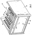
- dispensing unit 42 comprises a dispensing unit frame 44 that is insertable into cabinet frame 12 of cabinet 10. Coupled to dispensing unit frame 44 is a door 46 that may be opened to provide access to a dispenser frame 48 (see Fig. 3 ). As described in greater detail hereinafter, dispenser frame 48 may be withdrawn from dispensing unit frame 44 to provide access to various dispensing mechanisms 50 (see for example Figs. 4 and 5 ). As best shown in Fig. 2 , disposed below dispenser frame 48 is a dispense drawer 52 that receives items that fall from dispensing mechanisms 50 after such items have been selected at computer 30 (see Fig. 1 ).
- dispense drawer 52 may include a light 54 to guide the nurse user to the dispense drawer during dispensing operations.
- a handle 56 (see Figs. 1 and 2 ) may be provided on door 46 to facilitate opening of door 46.
- dispensed items may need to be returned to cabinet 10.
- various laws and regulations prohibit dispensed items from being placed back into cabinet 10.
- a return unit 58 attached to cabinet 10 may be a return unit 58 having a slidable (or rotatable) door 60 that may be opened to permit the item to be placed into unit 58.
- information regarding the return may be entered into computer 30.
- a light 62 on return unit 58 may be lighted to indicate to the nurse user that the item may be returned.
- Return unit 58 is preferably configured so that once an item is placed into the unit, the item cannot be returned from unit 58 unless a restock user or technician is authorized to gain access to return unit 58.
- a restock technician may be required to enter appropriate information into computer 30 to cause return unit 58 to unlock to allow access to the items within return unit 58.
- dispensing unit 42 may be used with a variety of dispensing cabinets.
- dispensing unit 42 may be placed within a cabinet that is used solely for dispensing pharmaceuticals and may only include drawers similar to drawers 38.
- dispensing unit 42 may be placed in a cabinet that only includes shelves that are similar to shelves 20.
- dispensing unit 42 may be used in cabinets having multiple shelves and/or drawers that are placed side by side in a vertical arrangement.
- the dispensing cabinet may include multiple dispensing units 42. These may be sized to the same size, or may be a different size.
- such dispensing cabinets may include other types of shelves, racks, drawers, and the like to facilitate the storage of items.
- shelf, rack, and drawer designs are described in U.S. Patent Nos. 6,272,394 ; 6,385,505 ; 5,805,455 ; 5,805,456 ; 5,745,366 ; 5,905,653 ; 5,927,540 ; 6,039,467 ; 6,151,536 ; 5,377,864 ; and 5,190,185 , previously incorporated herein by reference.
- door 46 is coupled to frame 44 using hinges 64. These permit door 46 to be opened to gain access to dispenser frame 48.
- arms 66 may be used to limit the extent to which door 46 may be opened so that it does not interfere with the opening of dispense drawer 52 as best illustrated in Fig. 4 .
- dispenser frame 48 and frame 44 include a track system 68 and 70 (and dispense drawer 52 and frame 44 may also include a similar track system) to permit dispense drawer 52 and dispenser frame 48 to easily be withdrawn from frame 44 as shown in Fig. 4 .
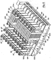
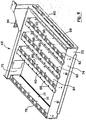
- dispenser frame 48 is constructed of a rectangular frame 72 having a front 74, a back 76 and two sides 78 and 80.
- Frame 72 is generally open except for a set of adjustable dividers 82 that are positioned between front 74 and back 76.
- another divider may be coupled to side 78 as illustrated in Fig. 6 .
- Front 74 and back 76 may include a set of mechanical interfaces, such as slots, holes, grooves, cut outs or the like to interface with tabs, protrusions, or the like on dividers 82. In this way, a blind matable connection between the dividers 82 and frame 72 may easily occur. Further, screws 84 may be used to securely couple dividers 82 to frame 72 once in place. By providing a series of mechanical interfaces, the placement of dividers 82 in dispenser frame 48 may be varied along front 74 and back 76. Further, any number of dividers 82 may be coupled to dispenser frame 48. In this way, the wide variety of dispensing mechanisms that are to be coupled to dividers 82 may be accommodated.
- mechanical interfaces such as slots, holes, grooves, cut outs or the like to interface with tabs, protrusions, or the like on dividers 82. In this way, a blind matable connection between the dividers 82 and frame 72 may easily occur. Further, screws 84 may be used to
- Back 76 may also include a series of electrical interfaces that interface with electrical interfaces on dividers 82 when they are mechanically coupled to dispenser frame 48.
- Dispenser frame 48 may also include a circuit board 86 (see Fig. 6 ) that may be used to facilitate communications between circuitry associated with the dividers 82 and computer 30.
- One capability of the circuitry used with cabinet 10 is the ability to detect the specific configuration of dividers 82 within dispenser frame 48. For example, appropriate circuitry in combination with computer 30 may be used to poll each one of the interfaces to determine if one of the dividers 82 is connected to that interface. This may be detected, for example, by sensing a short or low voltage signal that is created when divider 82 is coupled to a specific electrical interface.
- dispensing unit 42 may include a single dispenser frame 48 that has essentially the same width as dispense drawer 52 that is positioned beneath dispenser frame 48. Further, dispense drawer 52 may have essentially the same width as other drawers and/or shelves in the dispensing cabinet. In this way, a single dispenser frame may be employed to hold a wide variety of dispensing mechanisms that may all be simultaneously accessed by withdrawing dispenser frame 48. Further, the configuration of dispenser frame 48 may easily be varied simply by changing the configuration and/or number of dividers 82 that are included within dispenser frame 48. Further, the configuration of dividers 82 may be automatically sensed so that the dispensing cabinet will know the configuration of the dividers that will subsequently be needed for dispensing and/or restocking operations as described in greater detail hereinafter.
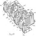
- Each divider 82 includes mechanical interfaces 88 and electrical interfaces 90 which are employed to receive dispensing mechanisms 50.
- dispensing mechanisms 50 a wide variety of dispensing mechanisms may be used.
- the dispensing mechanisms in general will be referred to with reference numeral 50.
- Specific types of dispensing mechanisms will use the same reference numeral followed by an "a", "b", etc.
- dispensing mechanisms 50a are syringe type dispensers
- dispensing mechanisms 50b are cassette type dispensers.
- two dispensing mechanisms 50b may be coupled together to form a double cassette dispenser.
- Mechanical interfaces 88 may conveniently comprise a threaded opening for receiving a screw.
- dispensing mechanisms 50b are screwed to one of the dividers 82 using a screw 92. Dispensing mechanism 50b then extends to an adjacent divider 82 to permit an electrical interface 94 on dispensing mechanism 50b to interface with electrical interface 90 of divider 82. In this way, dispensing mechanisms 50b may be coupled to dispenser frame 48 in a "plug and play" manner simply by plugging the dispensing mechanism into the appropriate electrical interface 90 and then using screw 92 to screw the dispensing mechanism to mechanical interface 88. The other dispensing mechanisms may be connected to dividers 82 in a similar manner.
- dividers 82 may be placed in any configuration to accommodate the number and/or size and/or type of dispensing mechanism 50 that may be used.
- dispensing mechanism 50 may be used.
- a wide variety of other dispensing mechanisms may be used that are capable of dispensing items based on an electrical signal that is passed through electrical interface 90 via control circuit board 86.
- Some examples of such dispensing mechanisms that may be used are described in U.S. Patent Nos. 5,377,864 ; and 5,190,185 , previously incorporated herein by reference.
- the invention is not intended to be limited to a specific type of dispensing mechanism.
- each dispensing mechanism 50 may include a button 96 that may be pressed by the restock user to produce a detectable event, such as a short or a low-voltage signal that may be detected by a circuit board that is disposed within each divider.
- the circuit boards are disposed below the connectors and contain address information for each of the dispensing mechanisms.
- the circuit boards may also be used to control actuation of the dispensing mechanisms and any sensing mechanisms.
- the address information may be transmitted from the circuit boards to computer 30.
- computer 30 may know the address of a particular dispensing mechanism when button 96 is pressed.
- the restock user may assign a given item to that particular dispensing mechanism and enter this into computer 30 so that computer 30 will have a record of the address of each dispensing mechanism and its associated item.
- dispensing mechanisms 50 may also include lights 97 that may be used to guide a restock technician to a particular dispensing mechanism during restocking operations as described in greater detail hereinafter.
- the light may be provided on the divider, and the dispensing mechanisms 50 may have a light pipe, such as a plastic conduit, to display the light.
- the dispensing mechanisms may include an identifier that uniquely identifies each dispensing mechanism. This information may be detected by the circuit board and sent to computer 30 so that computer 30 may assign a specific dispensing mechanism to a specific location. If the particular dispensing mechanism is removed to another location, computer 30 may detect the displacement and produce a warning signal. Examples of identifiers that may be used include RFID tags, EPROM chips, bar codes and the like. If such identifiers are used, configuration of the dispensing unit may occur automatically since computer 30 will know each specific dispensing mechanism and its location upon connection of the dispensing mechanism.
- Dispensing mechanisms 50a each comprise a housing 98 having an opening 100 that is configured to receive items in a stacked manner.
- opening 100 may conveniently be used to store syringes.
- Disposed at the bottom of dispensing mechanism 50a is a dispensing arrangement that is operated by a solenoid to dispense a single item each time the solenoid is operated. Alternatively, dispensing may occur by actuating a motor, other mechanical actuator or the like.
- the circuit board within the appropriate divider may be used to send a signal to the appropriate solenoid, motor or other mechanism to cause a dispensing arrangement to operate and dispense a single item.
- the dispensed item then falls into dispense drawer 52 that may be pulled from cabinet 10 to access the dispensed item.
- U.S. Patent Nos. 5,377,864 ; and 5,190,185 previously incorporated herein by reference.
- dispensing mechanisms 50b may be utilized to dispense pill packages, small ampoules, vials, and the like.
- Dispensing mechanisms 50b include a motor having a vertically oriented output shaft. Coupled to the output shaft is a gear system that is used to rotate a helical coil 302 surrounding a shaft that is contained within a housing 305. As best shown in Fig. 5A , a vial 304 is held in coil 302 and is moved downward when coil 302 is rotated. When vial 304 reaches the bottom of coil 302 is it dispensed and falls into dispense drawer 52. Hence, items may be dispensed from dispensing mechanisms 50b simply by sending an appropriate signal from computer 30 to the motor that rotates coil 302.
- circuit board 86 may be configured to send other signals to actuate other types of equipment.
- dispensing mechanisms that may be used are described in Fig. 5B . These may conveniently be coupled to dividers 82 in a manner similar to that previously described.
- One of these dispensing mechanisms is a small cassette type dispenser 50c that is similar to dispensing mechanism 50b except for its size. Dispensing mechanism 50c is particularly useful in dispensing pill packages.
- Another dispensing mechanism is a 5 ml vial dispensing mechanism 50d that is solenoid actuated in a manner similar to dispensing mechanism 50a.
- a 5 ml ampoule dispensing mechanism 50e that dispenses 5 ml ampoules using a solenoid in a manner similar to dispensing mechanism 50a.
- a large cassette dispensing mechanism 50f is employed to dispense pill packages, small ampoules, and vials.
- Dispensing mechanism 50f may be motor actuated in a manner similar to dispensing mechanism 50b.
- Dispensing mechanism 50d is illustrated in greater detail in Fig. 5C and is constructed of a housing 300 that houses a solenoid. The solenoid is used to operate a trap door system similar to that described in connection with dispensing mechanism 50a to dispense its contents. As also shown in Fig. 5C , dispensing mechanism 50d includes an electrical connector 91 that is configured to be inserted into connector 90 when dispensing mechanism 50d is coupled to a divider.
- dispenser frame 48 may be easily configured to accommodate a wide variety of dispensing mechanism types as well as arrangements.
- the divider configurations may automatically be determined and addresses for each of the dispensing mechanisms may easily be assigned since the appropriate circuitry may easily detect the location of each dispensing mechanism and may supply this information to computer 30 where items may be assigned to specific dispensing mechanisms.
- Tables 1-5 below illustrate various types of arrangements that are possible with dispenser frame 48.
- Table 1 describes an arrangement where dispenser frame 48 is configured to hold a maximum of five cassette-type dispensing mechanisms across the dispenser frame.
- Table 2 shows an arrangement where a dispenser frame may hold a maximum of two syringe-type dispensing mechanisms and one cassette-type dispensing mechanism across the dispenser frame.
- Table 3 illustrates an arrangement for holding a maximum of one syringe-type dispensing mechanism and three cassette-type dispensing mechanisms across the dispenser frame.
- the configuration between the syringe-type dispensing mechanisms and cassette-type dispensing mechanisms may be configured by removing and replacing dividers 82 as previously described.
- Table 4 illustrates a configuration having dividers that define two double wide spaces and one single wide space.
- the double wide spaces may be used to hold syringe-type dispensers while the single wide spaces may hold cassette-type dispensers. Further, one of the double wide spaces may also be used to hold two cassette-type dispensing mechanisms as well.
- Table 5 illustrates a dispenser frame configuration having dividers that define one double wide space and three single wide spaces. Further, the double wide space may be configured to hold two cassette-type dispensers in addition to syringe-type dispensers.
- circuit board 86 is incorporated into dispenser frame 48. In this way, circuit board 86 may easily be accessed for maintenance, repair or replacement simply by withdrawing dispenser frame 48 from dispensing unit 42. Further, incorporating circuit board 86 into dispenser frame 48 permits the dividers to be electrically coupled to electrical connectors using a blind matable connection. Circuit board 86 may be a passive connector board that channels commands to other boards used in connection with the dispensing cabinet. These other controllers may be on the same internal communication bus and may be used to filter out communications on non-functioning boards to allow the system to continue operating with a troublesome component.
- Circuit board 86 may be electrically coupled to another controller (that may in turn be coupled to frame 44 and electrically connected to computer 30) using various ribbon cables or other communication devices. These cables may be routed along the sides of dispensing unit 42 so as to not interfere with travel of dispenser frame 48 as it is withdrawn and pushed back into dispensing unit 42.
- the control board on frame 44 may be used as the main controller for operating the components associated with dispensing unit 42. Its functions may include manipulating and distributing power to the components in dispensing unit 42, generating module communications and interacting with the communication bus of the dispensing cabinet, and the like.
- the communications generated may include, but are not limited to, reading hardware configuration, auto calibrating a dispensing sensor system and running diagnostic scripts.
- door 46 may include an opening 108 for receiving a latch of a latching mechanism 109 that may be employed to lock door 46 to frame 44. In this way, access to dispenser frame 48 may be prevented until appropriate identification information is entered into computer 30. After such information has been entered, computer 30 may send a signal to operate latching mechanism 109 and permit door 46 to be unlocked.
- sensing system may detect when items have been dispensed from dispensing mechanisms 50 where they fall into dispense drawer 52.
- the sensing mechanism may transmit a beam or other signal below the dispensing mechanisms that may be interrupted as items fall into dispense drawer 52.
- One exemplary type of sensing system comprises IR detectors (hidden from view) and emitters 111 (see Fig. 6 ).
- the IR emitters 111 may be arranged along one of the dividers 82 to emit signals that are directed onto the opposite divider 82 that contains the detectors. In this way, the signal is sent laterally between the dividers.
- the sensing system may also have an automatic calibration feature for each IR emitter-detector.
- a calibration may be performed just prior to a dispensing event. Such a calibration may be beneficial in cases where light conditions change over time, such as during a bright day when ambient light enters when the frame is opened.
- the sensing system may be configured to sense the dispensing, even under different lighting conditions.
- each dispensing mechanism may be associated with it own sensor, including any of those described herein. In this way, each time a particular dispensing mechanism dispenses an item, the sensor may correlate the dispensing with the particular dispensing mechanism.
- Another way to accomplish such a feature is by using a second set of emitters and detectors that are mounted across the entire length of the dispenser frame (such as between front 74 and back 76 as shown in Fig. 6 ).
- a sensing system may be a vertical cavity surface emitting laser (VCSEL) sensing system.
- VCSEL vertical cavity surface emitting laser
- Such a system comprises a laser that transmits a signal across the bottoms of dispensing mechanisms 50.
- the laser is configured to reflect off a micro prism reflector so that the signal may be reflected back to a location near the laser source. If this signal varies, it may be used to detect that an item has been dispensed.
- a sensing system may be a VCSEL laser sensing system, from Honeywell. In this way, a confirmation may be made that an item was in fact dispensed when requested by the nurse user at computer 30.
- Such a sensing system is advantageous in that it reduces calibration times and is able to sense across the entire dispenser frame to reduce or eliminate errors.
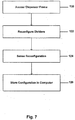
- Fig. 7 one method for configuring dividers 82 on dispenser frame 84 will be described.
- the process illustrated in Fig. 7 may be described in connection with the dispensing cabinet 10 and dispensing unit 42 as just described in connection with Figs. 1-6 .
- the restock user may log into the system using computer 30 and place computer 30 into the configuration mode.
- the restock user may then specify a zone that is to receive dispensing unit 42 so that its position within cabinet 10 is known.
- the dispenser frame is accessed as shown in step 120. This may conveniently be accomplished by withdrawing dispenser frame 48 from dispensing unit 42.
- the dividers may then be reconfigured in the desired position as illustrated in step 122.
- Control circuit board 86 may then be used to sense the reconfiguration of the dividers as illustrated in step 124. This information is transmitted to computer 30 for storage as shown in step 126.
- computer 30 could be configured to allow the restock user to manually input the configuration of the dividers so that a sensing system would not be needed.
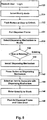
- restock user logs in as illustrated in step 128 by entering appropriate information into computer 30.
- the restock user may then select a modify mode at computer 30 as illustrated in step 130.
- door 46 on dispensing unit 42 may include a button 57 that the restock user may push to unlock door 46 as illustrated in step 132.
- latching mechanism 109 operates to unlatch the latch so that restock user may open the door.
- the restock user may then pull dispenser frame 48 out from the dispensing cabinet.
- a single dispenser frame may be employed so that the restock user may conveniently access all of the dividers when reconfiguring the dispensing mechanisms.
- the restock user may select a specific dispensing mechanism to modify as shown in step 136.
- the type of modification may depend on whether the dispensing mechanism is already coupled to a divider and simply needs to be reassigned a new type of item, or whether the dispensing mechanism is a new dispensing mechanism that is to be coupled to the divider.
- a query as to this effect is illustrated in step 138. If the dispensing mechanism is a new dispensing mechanism that is to be added to divider, the dispensing mechanism is installed to the divider as illustrated in step 140. As previously described, this may be accomplished by screwing a screw 92 into mechanical interface 88.
- button 96 may then be pressed to identify to computer 30 the specific dispensing mechanism that is being modified. This process is performed for both new and existing dispensing mechanisms. Display screen 34 may then permit the restock user to select an item to associate with the selected dispensing mechanism as illustrated in step 144. Since computer 30 knows the correct dispensing mechanism on a given divider once button 96 is pressed, it may assign that dispensing mechanism the selected item. As shown in step 146, the restock user may also enter the item quantity into the dispensing mechanism. Steps 136-146 may then be repeated to modify other dispensing units. When the process is finished the dispenser frame may be pushed back into the dispensing cabinet and the door closed as illustrated in step 148.
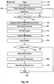
- a restock technician logs into computer 30 as illustrated in step 150 of Fig. 9 .
- a restock technician may be required to enter username and password information which is compared against a list of individuals that are authorized to access dispensing unit 42. If accepted, the restock technician may select the restock mode as illustrated in step 152.
- Computer 30 may have a record of all items stored in dispensing unit 42 along with their quantity. Further, computer 30 may include a restock list that was received from the pharmacy indicating which items are to be restocked, and may also include a quantity to restock. The restock technician may then select a restock list displayed on display screen 34 as illustrated in step 154.
- button 57 may light (and may optionally flash) to indicate to the restock technician where restocking should occur.
- Button 57 may be pressed which causes door 46 to unlock as illustrated in step 156. Door 46 may then be opened and dispenser frame 148 pulled out from dispensing unit 42 as illustrated in step 158.
- all lights 97 on dispensing mechanisms 50 that need to be restocked may flash to guide the restock technician to the dispensing mechanisms that need to be restocked as illustrated in step 160.
- the restock technician may then select one of the dispensing mechanisms to be restocked and press the associated button 96. This causes the associated light 97 to stop flashing and to continuously light as illustrated in step 162.
- Display screen 34 on computer 30 may also list the item that is associated with the dispensing mechanism that is being restocked as illustrated in step 164. Inventory information associated with the listed item may also be displayed on display screen 34.
- the restock technician may be asked to verify the number of items within dispensing mechanism 50 as illustrated in step 166. To facilitate counting of the items, an "empty dispenser" icon may be selected on display screen 34, and one of the buttons 96 may be pressed to dispense all of the items. Hence, the restock technician may manually count the items in the dispensing mechanism and enter this information into computer 30. If needed, the quantity may be modified and stored in computer 30. In most cases, however, a count back will not be needed because the sensors detect when items have been dispensed.
- the restock technician may then restock the items into dispensing mechanism 50 and enter the appropriate quantity.
- Button 96 may then be pressed to indicate that restocking of this dispensing mechanism is complete as illustrated in step 170.
- light 97 may then turn off to indicate restocking is complete.
- the restock technician may then determine whether additional dispensing mechanisms need to be restocked. If so, steps 162 through 170 are repeated. If not, the process ends at step 174. The restock technician may then push in dispenser frame 48 and close door 46 which then locks.
- restocking may easily occur by simply withdrawing dispenser frame 48 to gain access to all of the dispensing mechanisms. Further, the restock technician is guided to the specific dispensing mechanisms that need restocking.
- computer 30 may be coupled to a network so that restocking information may conveniently downloaded to computer 30 (such as from a pharmacy) to facilitate the restocking process.
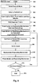
- Fig. 10 illustrates one exemplary method for dispensing items from dispensing unit 42 of cabinet 10.
- the nurse user logs into computer 30 as illustrated in step 176. This may require the nurse user to enter user name and password information to determine whether the nurse user may have access to the items stored in dispensing unit 42.
- a patient's identification information may also be entered.
- Computer 30 may then be placed into dispensing mode and the nurse user may enter a certain medication to be dispensed as illustrated in step 180. Conveniently, this medication may be selected from a list displayed on display screen 34.
- the nurse user may also be required to enter a dose as illustrated in step 182.
- the nurse user may also be asked to verify the quantity to dispense. If the nurse user wishes to dispense more than one item, the process proceeds to step 184 where steps 180 and 182 may be repeated for each additional item. Once all items have been selected, the process proceeds to step 186.
- step 186 the appropriate dispensing mechanisms 50 dispense the appropriate number of medications which fall into dispense drawer 52.
- light 54 on dispense drawer 52 may light to indicate the dispense drawer having the dispensed items as shown in step 188.
- the nurse user may then pull out dispense drawer 52 as shown step 190 and remove the dispensed medication as illustrated in step 192.
- dispense drawer 52 is closed as shown in step 194.
- the nurse user may wish to return one or more items as illustrated in step 196. If so, the nurse user may select a return mode at computer 30 as illustrated in step 198. Light 62 on return unit 58 may then light to guide the nurse user to the appropriate location for returning the dispensed items as shown in step 200. Door 60 may then be opened and the item returned as illustrated in step 202. The process then ends at step 204.
Landscapes
- General Physics & Mathematics (AREA)
- Physics & Mathematics (AREA)
- Engineering & Computer Science (AREA)
- Health & Medical Sciences (AREA)
- Medicinal Chemistry (AREA)
- Bioinformatics & Cheminformatics (AREA)
- Chemical & Material Sciences (AREA)
- Epidemiology (AREA)
- General Health & Medical Sciences (AREA)
- Medical Informatics (AREA)
- Primary Health Care (AREA)
- Public Health (AREA)
- Medical Preparation Storing Or Oral Administration Devices (AREA)
- Warehouses Or Storage Devices (AREA)
- Devices For Dispensing Beverages (AREA)
Claims (35)
- Dispositif pour la distribution d'articles, le dispositif comprenant :une armoire (10) ayant une façade, un dos, une paire de côtés et un compartiment ayant une zone de stockage;une pluralité de mécanismes de distribution (50) qui sont configurés de manière à maintenir une pluralité d'articles à l'intérieur de la zone de stockage;un indicateur visuel (97) associé avec chacun desdits mécanismes de distribution (50); etun calculateur (30) qui est couplé de manière fonctionnelle au mécanisme de distribution (50) et aux indicateurs visuels (97);caractérisé en ce quel'armoire (10) est construite à partir d'un cadre d'armoire (12);le dispositif comprenant en outre une unité de distribution (42) ayant un cadre d'unité (44) qui peut être inséré dans le cadre d'armoire (12), ladite unité de distribution (42) étant fixée à l'intérieur de ladite armoire (10);le cadre d'unité (44) comprenant un cadre de distribution (48) et un tiroir de distribution (52) disposé sous le cadre de distribution (48) de sorte que des articles distribués à partir des mécanismes de distribution (50) qui sont couplés de manière fonctionnelle au cadre de distribution (48) tombent dans le tiroir de distribution (52);le cadre de distribution (48) comprenant une pluralité de séparateurs (82), le cadre de distribution (48) et le cadre d'unité (44) comprenant un système de rails (68, 70) pour permettre au cadre de distribution (48) d'être retiré dudit cadre d'unité (44);une porte verrouillable (46) étant positionnée devant le cadre de distribution (49) et couplée au cadre d'unité (44);dans lequel la porte (46) peut être manoeuvrée pour fournir un accès au cadre de distribution (48);les séparateurs (82) étant reconfigurables dans une position désirée pour permettre l'ajustement de l'arrangement des mécanismes de distribution (50);un système de détection de séparation étant associé au cadre de distribution (48) pour détecter la configuration des séparateurs (82); etle calculateur (30) étant configuré pour stocker des informations sur la configuration des séparateurs (82) et pour actionner les indicateurs visuels (97) des mécanismes de distribution (50) qui doivent être réapprovisionnés ou modifiés.
- Dispositif selon la revendication 1 dans lequel le tiroir de distribution (52) a une largeur qui est essentiellement égale à la largeur du cadre de distribution (48).
- Dispositif selon la revendication 2, dans lequel le tiroir de distribution (52) s'étend essentiellement sur la totalité de la longueur de la façade et dans lequel le calculateur (30) est configuré pour envoyer un signal pour ouvrir automatiquement le tiroir de distribution (52) après qu'un article ait été distribué à partir d'un des mécanismes de distribution (50).
- Dispositif selon la revendication 1, dans lequel le calculateur (30) comprend en outre un enregistrement des articles dans l'armoire (10), de leur quantité et de leur emplacement.
- Dispositif selon la revendication 4, dans lequel le calculateur (30) est configuré pour permettre la sélection d'un article et pour envoyer un signal qui est utilisable par un des mécanismes de distribution (50) pour distribuer l'article sélectionné.
- Dispositif selon la revendication 5, dans lequel le tiroir de distribution (52) comprend une lampe (54) et dans lequel le calculateur (30) est configuré pour allumer la lampe de tiroir de distribution lors d'une sélection de l'article.
- Dispositif selon la revendication 4, dans lequel le calculateur (30) est configuré pour recevoir une entrée relative aux articles maintenus dans les mécanismes de distribution (50).
- Dispositif selon la revendication 7, dans lequel les mécanismes de distribution (50) comprennent chacun un mécanisme de détection qui peut être actionnable pour envoyer un signal au calculateur (30) quand il est actionné.
- Dispositif selon la revendication 8, dans lequel les mécanismes de détection peuvent être chacun actionnables pour indiquer au calculateur (30) que le mécanisme de distribution associé (50) a été marqué pour qu'on lui assigne un article, et dans lequel le calculateur (30) est configuré pour recevoir une entrée assignant un article au mécanisme de distribution (50) marqué.
- Dispositif selon la revendication 8, dans lequel les mécanismes de détection peuvent être chacun actionnables pour indiquer au calculateur (30) que le mécanisme de distribution associé (50) doit être réapprovisionné.
- Dispositif selon la revendication 1, dans lequel le calculateur (30) comprend un enregistrement des personnes qui peuvent utiliser l'armoire de distribution (10).
- Dispositif selon la revendication 11, dans lequel le calculateur (30) est configuré pour déverrouiller la porte (46) lors de l'entrée d'une information d'identification appropriée dans le calculateur (30) par une personne autorisée.
- Dispositif selon la revendication 12, dans lequel la porte (46) comprend une lampe, et dans lequel le calculateur (30) est configuré pour allumer la lampe de porte lors de la réception d'une requête de réapprovisionnement.
- Dispositif selon la revendication 13, dans lequel les indicateurs visuels (97) comprennent des lampes, et dans lequel le calculateur (30) est configuré pour allumer la lampe correspondant à chaque mécanisme de distribution (50) qui doit être réapprovisionné.
- Dispositif selon la revendication 14, dans lequel le calculateur (30) est configuré pour afficher le type d'article qui doit être réapprovisionné lorsque l'on presse sur l'une des lampes allumées.
- Dispositif selon la revendication 15, dans lequel le calculateur (30) est configuré pour produire un enregistrement de réapprovisionnement et pour éteindre la lampe du mécanisme de distribution associé (50) après un réapprovisionnement.
- Dispositif selon la revendication 1, dans lequel les séparateurs (82) comprennent des connecteurs qui sont configurés pour s'interfacer avec des connecteurs des distributeurs.
- Dispositif selon la revendication 1, dans lequel l'armoire (10) comprend en outre une unité de retour (58) qui est apte à recevoir les articles retournés.
- Dispositif selon la revendication 8, comprenant en outre un système de détection qui est configuré pour détecter le moment où les articles tombent à partir des mécanismes de distribution (50) et dans le tiroir de distribution (52).
- Dispositif selon la revendication 1, dans lequel le cadre de distribution (48) comprend en outre une carte de circuit imprimé de commande (86) qui est électriquement relié au calculateur (30) et qui est configuré pour être électriquement relié aux mécanismes de distribution (50).
- Dispositif selon la revendication 20, dans lequel chaque mécanisme de distribution (50) comprend un bouton (96) qui est configuré pour produire un événement détectable lorsqu'il est pressé, qui est détectable par une carte de circuit imprimé à l'intérieur de chaque séparateur (82).
- Dispositif selon la revendication 21, dans lequel les cartes de circuit imprimé contiennent des informations d'adresse pour chacun des mécanismes de distribution (50), le calculateur (30) étant configuré pour que les informations d'adresse soient transmises à partir d'un mécanisme de distribution (50) particulier quand le bouton (96) est pressé.
- Dispositif selon l'une quelconque des revendications 1 à 22, dans lequel le mécanisme de distribution (50) comprend un identifiant qui identifie de manière unique chaque mécanisme de distribution (50).
- Dispositif selon la revendication 23, dans lequel l'information relative à l'identifiant est détectable par la carte de circuit imprimé qui est configuré pour envoyer l'information au calculateur (30), qui est configuré pour assigné un mécanisme de distribution (50) à un emplacement spécifique.
- Dispositif selon la revendication 24, dans lequel l'identifiant est une étiquette RFID, une puce EPROM ou un code barre.
- Dispositif selon la revendication 1, comprenant en outre au moins un tiroir de maintien ayant une multitude d'emplacements de stockage qui sont configurés pour maintenir des articles additionnels.
- Dispositif selon la revendication 1, comprenant en outre au moins une étagère ayant des emplacements de stockage qui sont configurés pour maintenir des articles additionnels.
- Procédé pour configurer un dispositif de distribution, le procédé comprenant des étapes de :fournir un dispositif de distribution comprenant une armoire (10) ayant un compartiment;
une pluralité de mécanismes de distribution (50) qui maintiennent chacun une pluralité d'articles à l'intérieur du compartiment; et un calculateur (30);actionner un mécanisme de détection qui est associé à un des mécanismes de distribution (50) qui doit être configuré pour générer un signal; transmettre le signal au calculateur (30) pour indiquer que le mécanisme de distribution (50) qui est associé avec le mécanisme de détection actionné doit être configuré; etfournir un indicateur visuel (97) associé avec chacun des mécanismes de distribution (50);caractérisé par l'étape :d'utiliser une armoire (10) qui est construite à partir d'un cadre d'armoire (12);fournir une unité de distribution (42) ayant un cadre d'unité (44) qui est insérable dans le cadre d'armoire (12), l'unité de distribution (42) étant fixée à l'intérieur de ladite armoire (10);le cadre d'unité (44) comprenant un cadre de distribution (48) et un tiroir de distribution (52) disposé sous le cadre de distribution (48) de sorte que des articles distribués à partir de mécanismes de distribution (50) qui sont couplés de manière fonctionnelle au cadre de distribution (48) tombent dans le tiroir de distribution (52);coupler de manière fonctionnelle, le cadre de distribution (48) à l'armoire (10), dans lequel le cadre de distribution (48) et le cadre d'unité (44) comprennent un système de rails (68, 70) pour permettre au cadre de distribution (48) d'être retiré dudit cadre d'unité (44) et dans lequel le cadre de distribution (48) comprend une pluralité de séparateurs (82) pour maintenir la pluralité de mécanismes de distribution (50);fournir une porte verrouillable (46) étant couplée au cadre d'unité (44) et étant positionnée devant le cadre de distribution (48), dans lequel l'ouverture de la porte (46) permet d'accéder au cadre de distribution (48);fournir un système de détection de séparateurs associés avec le cadre de distribution (48) pour détecter la configuration des séparateurs (82);arranger les séparateurs (82) dans une configuration désirée;fournir un signal provenant du système de détection de séparateurs pour fournir une information concernant l'arrangement des séparateurs (82) au calculateur (30); etstocker des informations sur la configuration des séparateurs (82) dans le calculateur (30) et actionner les indicateurs visuels (97) des mécanismes de distribution (50) qui doivent être réapprovisionnés ou modifiés. - Procédé selon la revendication 28, comprenant en outre l'étape d'introduire dans le calculateur (30) un article à associer avec le mécanisme de distribution (50) qui est associé avec le mécanisme de détection actionné.
- Procédé selon la revendication 28, comprenant en outre le réapprovisionnement d'un article dans le mécanisme de distribution (50) qui est associé avec le mécanisme de détection actionné.
- Procédé selon la revendication 28, dans lequel le mécanisme de détection est actionné pour introduire une adresse d'un des mécanismes de distribution (50) dans le calculateur (30).
- Procédé selon la revendication 31, dans lequel l'adresse est déterminée en détectant l'emplacement du nouveau mécanisme de distribution (50) sur le séparateur (82) lorsque le mécanisme de détection est actionné.
- Procédé selon la revendication 32, dans lequel le mécanisme de détection comprend un bouton sur le mécanisme de distribution (50), et comprend en outre l'action de presser sur le bouton du mécanisme de distribution (50) pour entrer l'adresse du mécanisme de distribution (50) dans le calculateur (30).
- Procédé selon la revendication 29, dans lequel l'article qui a été associé avec le mécanisme de distribution (50) est introduit en sélectionnant un article à partir d'une liste d'articles affichés par le calculateur (30).
- Procédé selon la revendication 28, comprenant en outre l'étape d'introduire une requête dans le calculateur (30) pour distribuer un article, et actionner le mécanisme de distribution (50) pour distribuer l'article dans le tiroir de distribution (52).
Applications Claiming Priority (2)
| Application Number | Priority Date | Filing Date | Title |
|---|---|---|---|
| US10/434,724 US6975922B2 (en) | 2003-05-08 | 2003-05-08 | Secured dispensing cabinet and methods |
| PCT/US2004/014210 WO2004102492A2 (fr) | 2003-05-08 | 2004-05-07 | Compartiment de distribution securise et procedes |
Publications (3)
| Publication Number | Publication Date |
|---|---|
| EP1627320A2 EP1627320A2 (fr) | 2006-02-22 |
| EP1627320A4 EP1627320A4 (fr) | 2006-07-05 |
| EP1627320B1 true EP1627320B1 (fr) | 2017-04-05 |
Family
ID=33416771
Family Applications (1)
| Application Number | Title | Priority Date | Filing Date |
|---|---|---|---|
| EP04751552.3A Expired - Lifetime EP1627320B1 (fr) | 2003-05-08 | 2004-05-07 | Compartiment de distribution securise et procedes |
Country Status (7)
| Country | Link |
|---|---|
| US (3) | US6975922B2 (fr) |
| EP (1) | EP1627320B1 (fr) |
| JP (1) | JP4598773B2 (fr) |
| AU (1) | AU2004239714B2 (fr) |
| CA (1) | CA2523129C (fr) |
| ES (1) | ES2632292T3 (fr) |
| WO (1) | WO2004102492A2 (fr) |
Families Citing this family (157)
| Publication number | Priority date | Publication date | Assignee | Title |
|---|---|---|---|---|
| US7366772B2 (en) * | 2001-06-29 | 2008-04-29 | International Business Machines Corporation | Method and apparatus for creating and exposing order status within a supply chain having disparate systems |
| US8770372B2 (en) | 2012-02-03 | 2014-07-08 | Ellenby Technologies, Inc. | Coin and bill dispensing safe |
| US6847861B2 (en) | 2001-11-30 | 2005-01-25 | Mckesson Automation, Inc. | Carousel product for use in integrated restocking and dispensing system |
| AU2003261446A1 (en) * | 2002-08-09 | 2004-02-25 | Mckesson Automation Systems, Inc. | Controller for dispensing products |
| US7228198B2 (en) | 2002-08-09 | 2007-06-05 | Mckesson Automation Systems, Inc. | Prescription filling apparatus implementing a pick and place method |
| US7052097B2 (en) | 2002-12-06 | 2006-05-30 | Mckesson Automation, Inc. | High capacity drawer with mechanical indicator for a dispensing device |
| US6975922B2 (en) * | 2003-05-08 | 2005-12-13 | Omnicell, Inc. | Secured dispensing cabinet and methods |
| US8195328B2 (en) | 2003-09-19 | 2012-06-05 | Vesta Medical, Llc | Combination disposal and dispensing apparatus and method |
| CA2752578C (fr) | 2003-11-26 | 2016-02-02 | Mckesson Automation Inc. | Suite integree d'instruments medicaux |
| US20050171813A1 (en) * | 2004-02-04 | 2005-08-04 | Jordan Mchael L. | System for identifying and sorting orders |
| US7395897B2 (en) * | 2004-04-09 | 2008-07-08 | Vecta Oil & Gas, Ltd. | Accelerated weight drop configurable for use as a shear wave seismic energy source and a method of operation thereof |
| US7177721B2 (en) * | 2004-11-24 | 2007-02-13 | Cerner Innovation, Inc. | Computerized method and system for loading and/or unloading a tray having a light grid over a surface thereof |
| US7146247B2 (en) * | 2004-11-24 | 2006-12-05 | Cerner Innovation, Inc. | Computerized method and system for loading and/or unloading a tray using laser scanning technology |
| US7845041B2 (en) * | 2005-05-03 | 2010-12-07 | Colgate-Palmolive Company | Interactive musical toothbrush |
| US20070023512A1 (en) * | 2005-06-10 | 2007-02-01 | Mckesson Automation Inc. | Inventory management system using rfid tags to aid in dispensing and restocking inventory |
| ITMI20051727A1 (it) | 2005-09-19 | 2007-03-20 | Bottigelli Service S R L | Dispositivo di immagazzinamento e di prelievo di prodotti e suo procedimento di gestione |
| US7747347B2 (en) * | 2005-10-03 | 2010-06-29 | Sabal Medical, Inc. | Mobile medication storage and dispensing apparatus |
| WO2007064816A2 (fr) | 2005-12-02 | 2007-06-07 | Asd Specialty Healthcare, Inc. D/B/A Amerisourcebergen Specialty Group | Systeme et procede destines a la gestion et au suivi pharmaceutiques |
| US7630791B2 (en) * | 2005-12-09 | 2009-12-08 | CareFusion 303 Inc. | System and method for storing items and tracking item usage |
| FR2898116B1 (fr) * | 2006-03-06 | 2008-05-30 | Arx Sarl | Dispositif modulaire pour distribuer et ejecter automatiquement des produits stockes en rangees longitudinales paralleles |
| US8036773B2 (en) | 2006-05-10 | 2011-10-11 | Mckesson Automation Inc. | System, method and corresponding apparatus for storing, retrieving and delivering unit dose blisters |
| US8878676B2 (en) * | 2006-05-16 | 2014-11-04 | Gt Angel, Llc | Healthcare workstations and RFID devices for detecting medication errors |
| US7693603B2 (en) | 2007-01-22 | 2010-04-06 | John David Higham | Pharmaceutical dispensing system with coordinate guidance |
| US8251629B2 (en) * | 2007-02-09 | 2012-08-28 | Cerner Innovation, Inc. | Medication dispensing apparatus |
| US7974728B2 (en) * | 2007-05-04 | 2011-07-05 | Taiwan Semiconductor Manufacturing Company, Ltd. | System for extraction of key process parameters from fault detection classification to enable wafer prediction |
| US8009913B2 (en) | 2007-05-29 | 2011-08-30 | Mckesson Automation, Inc. | System, method, apparatus and computer program product for capturing human-readable text displayed on a unit dose package |
| US8738383B2 (en) | 2007-06-07 | 2014-05-27 | Aesynt Incorporated | Remotely and interactively controlling semi-automatic devices |
| US10395327B2 (en) * | 2007-06-19 | 2019-08-27 | Omnicell, Inc. | Management of patient transfer systems, methods, and devices |
| US8280550B2 (en) * | 2008-06-17 | 2012-10-02 | Omnicell, Inc. | Cabinet with remote integration |
| US8403908B2 (en) | 2007-12-17 | 2013-03-26 | Hospira, Inc. | Differential pressure based flow sensor assembly for medication delivery monitoring and method of using the same |
| US9026370B2 (en) | 2007-12-18 | 2015-05-05 | Hospira, Inc. | User interface improvements for medical devices |
| US8006903B2 (en) | 2007-12-28 | 2011-08-30 | Mckesson Automation, Inc. | Proximity-based inventory management system using RFID tags to aid in dispensing and restocking inventory |
| US8094028B2 (en) | 2007-12-28 | 2012-01-10 | Mckesson Automation, Inc. | Radio frequency alignment object, carriage and associated method of storing a product associated therewith |
| US20090169138A1 (en) * | 2007-12-28 | 2009-07-02 | Mckesson Automation Inc. | Medication and medical supply storage package and method |
| US20090194987A1 (en) * | 2008-01-31 | 2009-08-06 | Mckesson Automation Inc. | Method, apparatus and medication storage device for efficiently generating medication labels |
| US7992746B2 (en) * | 2008-02-11 | 2011-08-09 | Carefusion 303, Inc. | Method and apparatus for removing, inserting and securing receptacles in a receptacle tray |
| US11264124B2 (en) | 2008-02-20 | 2022-03-01 | Chudy Group, LLC | System and apparatus for item management |
| US8380346B2 (en) | 2008-02-20 | 2013-02-19 | Chundy Group, LLC | System and apparatus for item management |
| ES2328656B1 (es) * | 2008-05-14 | 2010-05-25 | Microtiker, S.L | Instalacion para la dispensacion automatica y reposicion semiautomatica de productos comerciales. |
| US8065924B2 (en) * | 2008-05-23 | 2011-11-29 | Hospira, Inc. | Cassette for differential pressure based medication delivery flow sensor assembly for medication delivery monitoring and method of making the same |
| US7819838B2 (en) * | 2008-09-02 | 2010-10-26 | Hospira, Inc. | Cassette for use in a medication delivery flow sensor assembly and method of making the same |
| US20100114027A1 (en) * | 2008-11-05 | 2010-05-06 | Hospira, Inc. | Fluid medication delivery systems for delivery monitoring of secondary medications |
| US8744621B2 (en) | 2009-01-09 | 2014-06-03 | Automed Technologies, Inc. | Medical cabinet access belt optimization system |
| US8103379B2 (en) | 2009-01-09 | 2012-01-24 | Automed Technologies, Inc. | Medication cabinetry |
| US9121197B2 (en) | 2009-01-09 | 2015-09-01 | Automed Technologies, Inc. | Cabinet system with improved drawer security |
| US8588966B2 (en) | 2009-01-09 | 2013-11-19 | Automed Technologies, Inc. | Cabinet system |
| US20100179890A1 (en) * | 2009-01-14 | 2010-07-15 | Cianciotto Jr Michael S | Tool inventory management system |
| US8484049B2 (en) * | 2009-01-30 | 2013-07-09 | Omnicell, Inc. | Tissue tracking |
| US8048022B2 (en) * | 2009-01-30 | 2011-11-01 | Hospira, Inc. | Cassette for differential pressure based medication delivery flow sensor assembly for medication delivery monitoring and method of making the same |
| US8386275B2 (en) | 2009-02-10 | 2013-02-26 | Timothy Chambers | Automatic pill dispensing device and method of use thereof |
| US7982612B2 (en) | 2009-02-20 | 2011-07-19 | Mckesson Automation Inc. | Methods, apparatuses, and computer program products for monitoring a volume of fluid in a flexible fluid bag |
| US9149405B2 (en) | 2009-03-03 | 2015-10-06 | Aesynt Incorporated | Medication storage and dispensing unit having a vial dispenser |
| US8929641B2 (en) | 2009-03-17 | 2015-01-06 | Aesynt Incorporated | System and method for determining the orientation of a unit dose package |
| US8405875B2 (en) | 2009-03-23 | 2013-03-26 | Mckesson Automation Inc. | Visibly-coded medication label and associated method, apparatus and computer program product for providing same |
| US20100249997A1 (en) | 2009-03-25 | 2010-09-30 | Greyshock Shawn T | System, method and corresponding apparatus for detecting perforations on a unit dose blister card |
| US8400277B2 (en) | 2009-03-30 | 2013-03-19 | Mckesson Automation Inc. | Methods, apparatuses, and computer program products for monitoring a transfer of fluid between a syringe and a fluid reservoir |
| US20100263947A1 (en) * | 2009-04-20 | 2010-10-21 | Chris John Reichart | Method for generating electricity from solar panels for an electrical system inside a truck/semi/vehicle |
| US20100280486A1 (en) * | 2009-04-29 | 2010-11-04 | Hospira, Inc. | System and method for delivering and monitoring medication |
| US8267491B2 (en) * | 2009-05-07 | 2012-09-18 | Hotel Outsource Management International, Inc. | Vending machine compartment assembly |
| EP2255774A1 (fr) * | 2009-05-25 | 2010-12-01 | Wiegand AG | Station de cintrage de médicaments |
| DE102009042891A1 (de) * | 2009-09-24 | 2011-03-31 | Giesecke & Devrient Gmbh | Behälter und System für die Bearbeitung von Banknoten |
| US8644982B2 (en) | 2009-09-30 | 2014-02-04 | Mckesson Automation Inc. | Unit dose packaging and associated robotic dispensing system and method |
| ES2335470B1 (es) * | 2009-10-14 | 2010-09-27 | Grifols, S.A. | Sistema electronico para la gestion de reposicion u el llenado de almacenes de planta en hospitales. |
| US8869667B2 (en) | 2009-12-04 | 2014-10-28 | Aesynt Incorporated | System, method and corresponding apparatus for singulating a unit dose blister card |
| US20110161108A1 (en) * | 2009-12-30 | 2011-06-30 | Mckesson Automation Inc. | Systems and methods for detecting diversion in drug dispensing |
| US8746908B2 (en) | 2010-01-27 | 2014-06-10 | Automed Technologies, Inc. | Medical supply cabinet with lighting features |
| US8640586B2 (en) | 2010-03-23 | 2014-02-04 | Mckesson Automation Inc. | Method and apparatus for facilitating cutting of a unit dose blister card |
| US8453548B2 (en) | 2010-03-23 | 2013-06-04 | Mckesson Automation Inc. | Apparatuses for cutting a unit dose blister card |
| US8593278B2 (en) | 2010-03-29 | 2013-11-26 | Mckesson Automation Inc. | Medication storage device usage status notifications |
| US8527090B2 (en) | 2010-03-30 | 2013-09-03 | Mckesson Automation Inc. | Method, computer program product and apparatus for facilitating storage and/or retrieval of unit dose medications |
| US8660687B2 (en) | 2010-03-30 | 2014-02-25 | Mckesson Automation Inc. | Medication bin having an electronic display and an associated method and computer program product |
| US8474691B2 (en) | 2010-03-31 | 2013-07-02 | Mckesson Automation Inc. | System, apparatus, method and computer-readable storage medium for generating medication labels |
| US20120012606A1 (en) | 2010-07-14 | 2012-01-19 | Mark Longley | Automated pharmacy system for dispensing unit doses of pharmaceuticals and the like |
| US8694162B2 (en) | 2010-12-20 | 2014-04-08 | Mckesson Automation, Inc. | Methods, apparatuses and computer program products for utilizing near field communication to guide robots |
| US8662606B2 (en) | 2011-03-17 | 2014-03-04 | Mckesson Automation Inc. | Drawer assembly and associated method for controllably limiting the slideable extension of a drawer |
| US8701931B2 (en) | 2011-03-30 | 2014-04-22 | Aesynt Incorporated | Medication dispensing cabinet and associated drawer assembly having pockets with controllably openable lids |
| US8588964B2 (en) | 2011-03-30 | 2013-11-19 | Mckesson Automation Inc. | Storage devices, systems, and methods for dispensing medications |
| US8554365B2 (en) | 2011-03-31 | 2013-10-08 | Mckesson Automation Inc. | Storage devices, systems, and methods for facilitating medication dispensing and restocking |
| US9412217B2 (en) | 2011-03-31 | 2016-08-09 | Aesynt Incorporated | Medication dispensing apparatus having conveyed carriers |
| KR101945217B1 (ko) | 2011-05-02 | 2019-02-07 | 옴니셀 인코포레이티드 | 시설-광역 약품 관리 시스템 |
| US9042607B2 (en) | 2011-05-02 | 2015-05-26 | Omnicell, Inc. | System and method for user access of dispensing unit |
| US9355220B2 (en) | 2011-05-02 | 2016-05-31 | Omnicell, Inc. | Medication dispensing cabinet systems and methods |
| US9355219B2 (en) | 2011-05-02 | 2016-05-31 | Omnicell, Inc. | Dispensing cabinet with articulating arm |
| US8670864B2 (en) | 2011-06-27 | 2014-03-11 | Cerner Innovation, Inc. | Dynamic refill level for medication dispensing apparatus |
| WO2013028497A1 (fr) | 2011-08-19 | 2013-02-28 | Hospira, Inc. | Systèmes et procédés pour une interface graphique comprenant une représentation graphique de données médicales |
| US9910965B2 (en) | 2011-09-16 | 2018-03-06 | Aesynt Incorporated | Systems, methods and computer program product for monitoring interactions with a medication storage device |
| US9471750B2 (en) | 2011-09-23 | 2016-10-18 | Aesynt Incorporated | Systems, methods and computer program product for streamlined medication dispensing |
| US8700210B2 (en) | 2011-09-29 | 2014-04-15 | Aesynt Incorporated | Systems, methods and computer program products for visually emphasizing portions of a medication storage device |
| US8650042B2 (en) | 2011-09-30 | 2014-02-11 | Mckesson Automation Inc. | Case and medication tracking |
| WO2013090709A1 (fr) | 2011-12-16 | 2013-06-20 | Hospira, Inc. | Système permettant de surveiller et d'administrer un médicament à un patient et méthode l'utilisant pour réduire les risques associés à une thérapie automatisée |
| US8983655B2 (en) | 2012-03-26 | 2015-03-17 | Aesynt Incorporated | Automated dispensing system and method |
| US9443370B2 (en) | 2012-03-26 | 2016-09-13 | Omnicare, Inc. | Method and apparatus for onsite distribution of medications and medical supplies |
| ES2741725T3 (es) | 2012-03-30 | 2020-02-12 | Icu Medical Inc | Sistema de detección de aire y método para detectar aire en una bomba de un sistema de infusión |
| US8755930B2 (en) | 2012-03-30 | 2014-06-17 | Aesynt Incorporated | Method, apparatus, and computer program product for optimization of item location in an automated storage system |
| US10045909B2 (en) | 2012-03-30 | 2018-08-14 | Aesynt Incorporated | Storage apparatus with support structures |
| US8807389B2 (en) | 2012-03-30 | 2014-08-19 | Aesynt Incorporated | Item dispensing unit |
| US20130282171A1 (en) * | 2012-04-18 | 2013-10-24 | Jvm Co., Ltd. | Medicine storage apparatus |
| US8869364B2 (en) | 2012-06-25 | 2014-10-28 | Aesynt Incorporated | Material separating tool |
| US9123195B2 (en) | 2012-06-29 | 2015-09-01 | Aesynt Incorporated | Modular, multi-orientation conveyor |
| US9171246B2 (en) | 2012-06-29 | 2015-10-27 | Aesynt Incorporated | System, methods, apparatuses, and computer program products for detecting that an object has been accessed |
| US10360751B2 (en) * | 2012-07-23 | 2019-07-23 | Pharmadva, LLC | Object dispenser having a variable orifice and image identification |
| US10463788B2 (en) | 2012-07-31 | 2019-11-05 | Icu Medical, Inc. | Patient care system for critical medications |
| KR101728104B1 (ko) * | 2012-09-28 | 2017-05-02 | 이노베이티브 프로덕트 어치브먼츠, 엘엘씨 | 물품 지급 장치 |
| CN103158979A (zh) * | 2012-10-11 | 2013-06-19 | 苏州艾隆科技股份有限公司 | 出药机 |
| US20140108027A1 (en) | 2012-10-12 | 2014-04-17 | Mckesson Automation Inc. | Apparatuses, systems, and methods for delivering medications from a central pharmacy to a patient in a healthcare facility |
| US9150119B2 (en) | 2013-03-15 | 2015-10-06 | Aesynt Incorporated | Apparatuses, systems, and methods for anticipating and delivering medications from a central pharmacy to a patient using a track based transport system |
| JP6490587B2 (ja) | 2012-11-19 | 2019-03-27 | オムニセル, インコーポレイテッド | 複数のrfidリーダを備えた保管キャビネット |
| US9814828B2 (en) | 2013-03-15 | 2017-11-14 | Aesynt Incorporated | Method and apparatus for preparing and monitoring an intravenous fluid bag |
| US9443371B2 (en) | 2013-03-27 | 2016-09-13 | Aesynt Incorporated | Medication dispensing cabinet, computing device and associated method for measuring the force applied to a drawer |
| US9884695B2 (en) | 2013-03-28 | 2018-02-06 | Aesynt Incorporated | Compartment configured for presentation of stored articles |
| US9195803B2 (en) | 2013-03-28 | 2015-11-24 | Aesynt Incorporated | Systems, methods, apparatuses, and computer program products for providing controlled access to intravenous bags |
| US9626817B2 (en) | 2013-03-29 | 2017-04-18 | Aesynt Incorporated | Apparatuses, systems, and methods for storing and dispensing medication proximate a patient |
| US10046112B2 (en) | 2013-05-24 | 2018-08-14 | Icu Medical, Inc. | Multi-sensor infusion system for detecting air or an occlusion in the infusion system |
| EP3003442B1 (fr) | 2013-05-29 | 2020-12-30 | ICU Medical, Inc. | Système de perfusion et procédé d'utilisation évitant la sursaturation d'un convertisseur analogique-numérique |
| AU2014274146B2 (en) | 2013-05-29 | 2019-01-24 | Icu Medical, Inc. | Infusion system which utilizes one or more sensors and additional information to make an air determination regarding the infusion system |
| US20150076973A1 (en) * | 2013-09-19 | 2015-03-19 | Donald A. PIERSON | Furniture for and method of dispensing diapers |
| US10235652B2 (en) * | 2013-09-26 | 2019-03-19 | Sonia Varrasso | Inventory control system |
| US20150133861A1 (en) | 2013-11-11 | 2015-05-14 | Kevin P. McLennan | Thermal management system and method for medical devices |
| US10984901B1 (en) | 2013-12-18 | 2021-04-20 | Stuart Renwick Locklear | Method and system to implement medical information tracking system and medication dispenser |
| US9365315B2 (en) | 2014-01-28 | 2016-06-14 | Omnicell, Inc. | Versatile lighting system for dispensing cabinets |
| ES2776363T3 (es) | 2014-02-28 | 2020-07-30 | Icu Medical Inc | Sistema de infusión y método que utiliza detección óptica de aire en línea de doble longitud de onda |
| WO2015184366A1 (fr) | 2014-05-29 | 2015-12-03 | Hospira, Inc. | Système et pompe de perfusion à rattrapage de débit d'administration réglable en boucle fermée |
| US10143795B2 (en) | 2014-08-18 | 2018-12-04 | Icu Medical, Inc. | Intravenous pole integrated power, control, and communication system and method for an infusion pump |
| CN104443982B (zh) * | 2014-10-30 | 2016-08-24 | 江苏迅捷装具科技有限公司 | 处方药品缓存快速发药系统及方法 |
| US11344668B2 (en) | 2014-12-19 | 2022-05-31 | Icu Medical, Inc. | Infusion system with concurrent TPN/insulin infusion |
| US9818251B2 (en) | 2015-02-27 | 2017-11-14 | Omnicell, Inc. | Unit dose dispensing systems and methods |
| US10850024B2 (en) | 2015-03-02 | 2020-12-01 | Icu Medical, Inc. | Infusion system, device, and method having advanced infusion features |
| AU2016267763B2 (en) | 2015-05-26 | 2021-07-08 | Icu Medical, Inc. | Disposable infusion fluid delivery device for programmable large volume drug delivery |
| RU2597456C1 (ru) * | 2015-08-21 | 2016-09-10 | Кирилл Эдуардович Пищик | Торговый автомат для дистанционной продажи и способ дистанционной продажи контролируемых товаров |
| CA2939591C (fr) | 2015-08-25 | 2021-11-09 | Chudy Group, LLC | Systeme de conditionnement de medicament automatique multimode |
| US10515722B2 (en) | 2015-10-15 | 2019-12-24 | Omnicell, Inc. | Medical equipment with diversion mechanism |
| US10685091B1 (en) * | 2016-02-02 | 2020-06-16 | PharmRight Corporation | System and method for dispensing pharmaceutical doses |
| US10186100B2 (en) | 2016-02-09 | 2019-01-22 | Omnicell, Inc. | Relay box |
| EP4085944A1 (fr) | 2016-05-13 | 2022-11-09 | ICU Medical, Inc. | Système de pompe à perfusion avec rinçage automatique de la ligne commune |
| WO2017214441A1 (fr) | 2016-06-10 | 2017-12-14 | Icu Medical, Inc. | Capteur de flux acoustique pour mesures continues de débit de médicament et commande par rétroaction de perfusion |
| US10517799B2 (en) | 2017-08-31 | 2019-12-31 | Omnicell, Inc. | Unit dose dispensing mechanisms |
| US11735304B2 (en) | 2017-09-26 | 2023-08-22 | Mckesson Corporation | Robotic dispensary system and methods |
| US10358247B2 (en) | 2017-10-27 | 2019-07-23 | Chudy Group, LLC | Compartmentalized container loading and management system |
| US10663218B2 (en) | 2017-11-17 | 2020-05-26 | Omnicell, Inc. | Dispensing system with temperature controlled drawers |
| US11536506B2 (en) | 2018-09-12 | 2022-12-27 | Omnicell, Inc. | Temperature controlled dispense drawer |
| US10089055B1 (en) | 2017-12-27 | 2018-10-02 | Icu Medical, Inc. | Synchronized display of screen content on networked devices |
| US11348672B2 (en) | 2017-12-29 | 2022-05-31 | Cerner Innovation, Inc. | Medical order entry integration with automated dispensing systems |
| WO2019143734A1 (fr) * | 2018-01-17 | 2019-07-25 | Zanghi Robert Joseph | Améliorations apportées à la sécurité d'une chaîne d'approvisionnement |
| US10806676B2 (en) | 2018-01-30 | 2020-10-20 | Omnicell, Inc. | Relay tray |
| CN108986316A (zh) * | 2018-07-24 | 2018-12-11 | 吉林工程技术师范学院 | 一种自动售货机 |
| WO2020061372A1 (fr) * | 2018-09-20 | 2020-03-26 | Supplypro, Inc. | Appareil, système et procédés de stockage modulaire |
| CN110013409B (zh) * | 2019-04-28 | 2020-08-28 | 漯河医学高等专科学校 | 一种用于妇产科护理的药物供给装置 |
| CN110322638A (zh) * | 2019-08-14 | 2019-10-11 | 山东便利客智能科技有限公司 | 一种自动售药机 |
| USD939079S1 (en) | 2019-08-22 | 2021-12-21 | Icu Medical, Inc. | Infusion pump |
| US11426329B2 (en) * | 2019-11-12 | 2022-08-30 | Omnicell, Inc. | Dispensing systems and methods for prefilled syringes |
| US11278671B2 (en) | 2019-12-04 | 2022-03-22 | Icu Medical, Inc. | Infusion pump with safety sequence keypad |
| US11505354B1 (en) | 2020-02-19 | 2022-11-22 | Nelson Irrigation Coporation | Packaging/inspection system for a nozzle pivot package |
| CA3189781A1 (fr) | 2020-07-21 | 2022-01-27 | Icu Medical, Inc. | Dispositifs de transfert de fluide et procedes d'utilisation |
| CN112082306A (zh) * | 2020-09-08 | 2020-12-15 | 枣庄市妇幼保健院 | 一种多功能药房药品调剂柜 |
| US11135360B1 (en) | 2020-12-07 | 2021-10-05 | Icu Medical, Inc. | Concurrent infusion with common line auto flush |
| WO2023170680A1 (fr) | 2022-03-08 | 2023-09-14 | Equashield Medical Ltd | Station de transfert de fluide dans un système de préparation pharmaceutique robotique |
| CN116552967B (zh) * | 2023-07-11 | 2023-09-19 | 佳木斯大学 | 一种医疗临床科用消毒液存放收纳架 |
Citations (2)
| Publication number | Priority date | Publication date | Assignee | Title |
|---|---|---|---|---|
| WO1998026746A2 (fr) * | 1996-12-05 | 1998-06-25 | Omnicell Technologies, Inc. | Meuble de remplacement et procedes applicables a un appareil distributeur |
| EP1053738A2 (fr) * | 1999-05-20 | 2000-11-22 | SANYO ELECTRIC Co., Ltd. | Appareil de remplissage pour préparations solides |
Family Cites Families (51)
| Publication number | Priority date | Publication date | Assignee | Title |
|---|---|---|---|---|
| US2606803A (en) * | 1948-04-30 | 1952-08-12 | Craig Machine Inc | Vending machine |
| US2653850A (en) * | 1949-11-17 | 1953-09-29 | Theodore F Vollten | Combination storage and dispensing rack |
| US3437238A (en) * | 1967-08-28 | 1969-04-08 | Marion J Luba | Automatic butter dispenser |
| US4062385A (en) * | 1975-03-14 | 1977-12-13 | Eastman Kodak Company | Toner handling apparatus |
| US3998356A (en) * | 1975-08-28 | 1976-12-21 | Arthur A. Bennett, Jr. | Electronic system for article dispensing apparatus |
| US4225056A (en) * | 1978-09-28 | 1980-09-30 | Artag Plastics Corporation | Computerized vending machine |
| US4267942A (en) * | 1979-06-20 | 1981-05-19 | John B. Wick, Jr. | Pharmaceutical dispensing cabinet |
| US4360125A (en) * | 1980-03-10 | 1982-11-23 | Medtronic, Inc. | Medication inventory device |
| US4519522A (en) * | 1981-07-06 | 1985-05-28 | Photo Vending Corporation | Apparatus and method for storing and retrieving articles |
| DE3233559C2 (de) * | 1982-09-10 | 1984-11-29 | Agfa-Gevaert Ag, 5090 Leverkusen | Vorrichtung zum lichtdichten Einführen eines Filmstapelbehälters |
| GB8323810D0 (en) * | 1983-09-06 | 1983-10-05 | Banks E J K | Supervising access to individual items |
| US4573606A (en) * | 1983-09-12 | 1986-03-04 | Kermit E. Lewis | Automatic pill dispenser and method of administering medical pills |
| US4572403A (en) * | 1984-02-01 | 1986-02-25 | Rafael Benaroya | Timed dispensing device for tablets, capsules, and the like |
| US4663621A (en) * | 1984-03-30 | 1987-05-05 | Field David J | Medicine cabinet |
| US4695954A (en) * | 1984-10-31 | 1987-09-22 | Rose Robert J | Modular medication dispensing system and apparatus utilizing portable memory device |
| JPS6392984U (fr) * | 1986-12-05 | 1988-06-15 | ||
| US4814592A (en) * | 1986-05-29 | 1989-03-21 | Videomat Associates | Apparatus and method for storing and retrieving articles |
| DE3702407A1 (de) * | 1986-11-06 | 1988-05-11 | Nsm Apparatebau Gmbh Kg | Vermiet- und verkaufsmaschine, insbesondere fuer videokassetten, und kassettenbox fuer videokassetten |
| US4785969A (en) * | 1986-11-10 | 1988-11-22 | Pyxis Corporation | Medication dispensing system |
| SE457917B (sv) * | 1987-05-19 | 1989-02-06 | Electrolux Ab | Skaap foer att tillhandehaalla olika artiklar placerade imagasin, som aer loesbart fastgoerbara i fack i skaapet |
| US4847764C1 (en) * | 1987-05-21 | 2001-09-11 | Meditrol Inc | System for dispensing drugs in health care instituions |
| US4811764A (en) * | 1987-10-19 | 1989-03-14 | Mclaughlin John T | Medication dispenser station |
| SU1698598A1 (ru) * | 1987-12-11 | 1991-12-15 | В.А. Васильев | Бытовой холодильник |
| US4967928A (en) * | 1988-06-09 | 1990-11-06 | Carter Cheryl L | Inventory control including individual patient listing and medical chart record for medication cart |
| EP0594268B1 (fr) * | 1989-05-25 | 1997-01-08 | Baxter International Inc. | Cartouche contenant des containers de médicaments |
| US5267174A (en) * | 1989-09-29 | 1993-11-30 | Healthtech Services Corp. | Interactive medication delivery system |
| US5190185A (en) * | 1990-05-18 | 1993-03-02 | Baxter International Inc. | Medication transport and dispensing magazine |
| JP3468790B2 (ja) * | 1993-01-19 | 2003-11-17 | 健 柳沢 | 搬送装置 |
| US5790409A (en) * | 1993-01-25 | 1998-08-04 | Medselect Systems, Inc. | Inventory monitoring and dispensing system for medical items |
| US5912818A (en) | 1993-01-25 | 1999-06-15 | Diebold, Incorporated | System for tracking and dispensing medical items |
| JP3354219B2 (ja) * | 1993-07-07 | 2002-12-09 | 三洋電機株式会社 | 薬品保管庫 |
| US6272394B1 (en) * | 1993-07-21 | 2001-08-07 | Omnicell.Com | Methods and apparatus for dispensing items |
| US6385505B1 (en) * | 1993-07-21 | 2002-05-07 | Omnicell.Com | Methods and apparatus for dispensing items |
| US5431299A (en) * | 1994-01-26 | 1995-07-11 | Andrew E. Brewer | Medication dispensing and storing system with dispensing modules |
| US5905653A (en) * | 1994-07-14 | 1999-05-18 | Omnicell Technologies, Inc. | Methods and devices for dispensing pharmaceutical and medical supply items |
| US5805456A (en) * | 1994-07-14 | 1998-09-08 | Omnicell Technologies, Inc. | Device and method for providing access to items to be dispensed |
| US5745366A (en) * | 1994-07-14 | 1998-04-28 | Omnicell Technologies, Inc. | Pharmaceutical dispensing device and methods |
| US6760643B2 (en) | 1994-10-11 | 2004-07-06 | Omnicell, Inc. | Methods and apparatus for dispensing items |
| JP2933837B2 (ja) | 1994-10-21 | 1999-08-16 | 株式会社湯山製作所 | 薬剤包装装置 |
| US5797515A (en) * | 1995-10-18 | 1998-08-25 | Adds, Inc. | Method for controlling a drug dispensing system |
| DE19728885C2 (de) * | 1997-07-07 | 2000-10-19 | Reinhard Albers | Rechnergestützt arbeitendes Ausleihsystem |
| US5927540A (en) * | 1997-08-20 | 1999-07-27 | Omnicell Technologies, Inc. | Controlled dispensing system and method |
| US6062438A (en) * | 1998-04-20 | 2000-05-16 | Mars, Inc. | Apparatus for dispensing of bulk product |
| US6151536A (en) * | 1998-09-28 | 2000-11-21 | Omnicell.Com | Dispensing system and methods |
| US6564121B1 (en) * | 1999-09-22 | 2003-05-13 | Telepharmacy Solutions, Inc. | Systems and methods for drug dispensing |
| US6658322B1 (en) * | 2000-05-05 | 2003-12-02 | Medselect Inc. | System and method for tracking medical items and supplies |
| WO2003074396A1 (fr) * | 2002-03-04 | 2003-09-12 | Alexandre Maldonado | Mecanisme de distribution ajustable faisant intervenir une poussee vers l'avant |
| JP2002156181A (ja) * | 2000-11-16 | 2002-05-31 | Yozan Inc | 冷蔵庫 |
| JP4617011B2 (ja) | 2001-03-13 | 2011-01-19 | 株式会社湯山製作所 | 薬剤収容取出し装置 |
| JP2002282342A (ja) * | 2001-03-26 | 2002-10-02 | Naka Instruments Co Ltd | 薬品管理システム |
| US6975922B2 (en) * | 2003-05-08 | 2005-12-13 | Omnicell, Inc. | Secured dispensing cabinet and methods |
-
2003
- 2003-05-08 US US10/434,724 patent/US6975922B2/en not_active Expired - Lifetime
-
2004
- 2004-05-07 ES ES04751552.3T patent/ES2632292T3/es not_active Expired - Lifetime
- 2004-05-07 WO PCT/US2004/014210 patent/WO2004102492A2/fr active Application Filing
- 2004-05-07 AU AU2004239714A patent/AU2004239714B2/en active Active
- 2004-05-07 JP JP2006532834A patent/JP4598773B2/ja not_active Expired - Lifetime
- 2004-05-07 EP EP04751552.3A patent/EP1627320B1/fr not_active Expired - Lifetime
- 2004-05-07 CA CA2523129A patent/CA2523129C/fr not_active Expired - Lifetime
-
2005
- 2005-08-17 US US11/206,660 patent/US7571024B2/en not_active Expired - Lifetime
-
2009
- 2009-07-02 US US12/496,746 patent/US7835819B2/en not_active Expired - Lifetime
Patent Citations (2)
| Publication number | Priority date | Publication date | Assignee | Title |
|---|---|---|---|---|
| WO1998026746A2 (fr) * | 1996-12-05 | 1998-06-25 | Omnicell Technologies, Inc. | Meuble de remplacement et procedes applicables a un appareil distributeur |
| EP1053738A2 (fr) * | 1999-05-20 | 2000-11-22 | SANYO ELECTRIC Co., Ltd. | Appareil de remplissage pour préparations solides |
Also Published As
| Publication number | Publication date |
|---|---|
| ES2632292T3 (es) | 2017-09-12 |
| EP1627320A4 (fr) | 2006-07-05 |
| CA2523129A1 (fr) | 2004-11-25 |
| US20100070074A1 (en) | 2010-03-18 |
| AU2004239714A1 (en) | 2004-11-25 |
| WO2004102492A3 (fr) | 2005-08-18 |
| US7835819B2 (en) | 2010-11-16 |
| US6975922B2 (en) | 2005-12-13 |
| WO2004102492A2 (fr) | 2004-11-25 |
| JP2007502191A (ja) | 2007-02-08 |
| AU2004239714B2 (en) | 2011-02-03 |
| JP4598773B2 (ja) | 2010-12-15 |
| US20040225409A1 (en) | 2004-11-11 |
| EP1627320A2 (fr) | 2006-02-22 |
| US20060085094A1 (en) | 2006-04-20 |
| US7571024B2 (en) | 2009-08-04 |
| CA2523129C (fr) | 2013-01-29 |
Similar Documents
| Publication | Publication Date | Title |
|---|---|---|
| EP1627320B1 (fr) | Compartiment de distribution securise et procedes | |
| US6788997B1 (en) | Medical cabinet with adjustable drawers | |
| US6112502A (en) | Restocking method for medical item dispensing system | |
| US5912818A (en) | System for tracking and dispensing medical items | |
| EP3373883B1 (fr) | Station de technologie médicale et procédé d'utilisation | |
| EP3261496B1 (fr) | Systèmes et procédés de distribution de dose unitaire | |
| US5848593A (en) | System for dispensing a kit of associated medical items | |
| US5993046A (en) | System for dispensing medical items by brand or generic name | |
| US8423180B1 (en) | System for tracking and dispensing medical items from environmentally controlled storage area | |
| US5745366A (en) | Pharmaceutical dispensing device and methods | |
| US7085621B2 (en) | Method of operating a dispensing cabinet | |
| US6108588A (en) | Restocking method for medical item dispensing system | |
| US6163737A (en) | Medical item dispensing apparatus | |
| US7689317B2 (en) | Medical item inventory monitoring system with automatic electronic reordering | |
| US7596426B2 (en) | Method of monitoring medical item inventory | |
| US20030105554A1 (en) | Dispensing cabinet with unit dose dispensing drawer | |
| WO1995020804A1 (fr) | Systeme d'administration de medicament avec modules de stockage et de distribution du medicament | |
| EP0954800B1 (fr) | Dispositif et procede de distribution de produits pharmaceutiques | |
| AU728806B2 (en) | Pharmaceutical dispensing device and methods | |
| US11426329B2 (en) | Dispensing systems and methods for prefilled syringes | |
| WO1999006920A1 (fr) | Systeme de pistage informatise gerant les stocks de produits medicaux destines a des dispositifs de stockage non fermes |
Legal Events
| Date | Code | Title | Description |
|---|---|---|---|
| PUAI | Public reference made under article 153(3) epc to a published international application that has entered the european phase |
Free format text: ORIGINAL CODE: 0009012 |
|
| 17P | Request for examination filed |
Effective date: 20051202 |
|
| AK | Designated contracting states |
Kind code of ref document: A2 Designated state(s): AT BE BG CH CY CZ DE DK EE ES FI FR GB GR HU IE IT LI LU MC NL PL PT RO SE SI SK TR |
|
| AX | Request for extension of the european patent |
Extension state: AL HR LT LV MK |
|
| A4 | Supplementary search report drawn up and despatched |
Effective date: 20060606 |
|
| DAX | Request for extension of the european patent (deleted) | ||
| 17Q | First examination report despatched |
Effective date: 20061106 |
|
| GRAP | Despatch of communication of intention to grant a patent |
Free format text: ORIGINAL CODE: EPIDOSNIGR1 |
|
| INTG | Intention to grant announced |
Effective date: 20161012 |
|
| GRAS | Grant fee paid |
Free format text: ORIGINAL CODE: EPIDOSNIGR3 |
|
| GRAA | (expected) grant |
Free format text: ORIGINAL CODE: 0009210 |
|
| AK | Designated contracting states |
Kind code of ref document: B1 Designated state(s): AT BE BG CH CY CZ DE DK EE ES FI FR GB GR HU IE IT LI LU MC NL PL PT RO SE SI SK TR |
|
| REG | Reference to a national code |
Ref country code: GB Ref legal event code: FG4D |
|
| REG | Reference to a national code |
Ref country code: CH Ref legal event code: EP |
|
| REG | Reference to a national code |
Ref country code: AT Ref legal event code: REF Ref document number: 882415 Country of ref document: AT Kind code of ref document: T Effective date: 20170415 |
|
| REG | Reference to a national code |
Ref country code: IE Ref legal event code: FG4D |
|
| REG | Reference to a national code |
Ref country code: FR Ref legal event code: PLFP Year of fee payment: 14 |
|
| REG | Reference to a national code |
Ref country code: DE Ref legal event code: R096 Ref document number: 602004051043 Country of ref document: DE |
|
| REG | Reference to a national code |
Ref country code: NL Ref legal event code: MP Effective date: 20170405 |
|
| REG | Reference to a national code |
Ref country code: ES Ref legal event code: FG2A Ref document number: 2632292 Country of ref document: ES Kind code of ref document: T3 Effective date: 20170912 |
|
| REG | Reference to a national code |
Ref country code: AT Ref legal event code: MK05 Ref document number: 882415 Country of ref document: AT Kind code of ref document: T Effective date: 20170405 |
|
| PG25 | Lapsed in a contracting state [announced via postgrant information from national office to epo] |
Ref country code: NL Free format text: LAPSE BECAUSE OF FAILURE TO SUBMIT A TRANSLATION OF THE DESCRIPTION OR TO PAY THE FEE WITHIN THE PRESCRIBED TIME-LIMIT Effective date: 20170405 |
|
| PG25 | Lapsed in a contracting state [announced via postgrant information from national office to epo] |
Ref country code: FI Free format text: LAPSE BECAUSE OF FAILURE TO SUBMIT A TRANSLATION OF THE DESCRIPTION OR TO PAY THE FEE WITHIN THE PRESCRIBED TIME-LIMIT Effective date: 20170405 Ref country code: GR Free format text: LAPSE BECAUSE OF FAILURE TO SUBMIT A TRANSLATION OF THE DESCRIPTION OR TO PAY THE FEE WITHIN THE PRESCRIBED TIME-LIMIT Effective date: 20170706 Ref country code: AT Free format text: LAPSE BECAUSE OF FAILURE TO SUBMIT A TRANSLATION OF THE DESCRIPTION OR TO PAY THE FEE WITHIN THE PRESCRIBED TIME-LIMIT Effective date: 20170405 |
|
| PG25 | Lapsed in a contracting state [announced via postgrant information from national office to epo] |
Ref country code: SE Free format text: LAPSE BECAUSE OF FAILURE TO SUBMIT A TRANSLATION OF THE DESCRIPTION OR TO PAY THE FEE WITHIN THE PRESCRIBED TIME-LIMIT Effective date: 20170405 Ref country code: BG Free format text: LAPSE BECAUSE OF FAILURE TO SUBMIT A TRANSLATION OF THE DESCRIPTION OR TO PAY THE FEE WITHIN THE PRESCRIBED TIME-LIMIT Effective date: 20170705 Ref country code: PL Free format text: LAPSE BECAUSE OF FAILURE TO SUBMIT A TRANSLATION OF THE DESCRIPTION OR TO PAY THE FEE WITHIN THE PRESCRIBED TIME-LIMIT Effective date: 20170405 |
|
| REG | Reference to a national code |
Ref country code: CH Ref legal event code: PL |
|
| REG | Reference to a national code |
Ref country code: DE Ref legal event code: R097 Ref document number: 602004051043 Country of ref document: DE |
|
| PG25 | Lapsed in a contracting state [announced via postgrant information from national office to epo] |
Ref country code: RO Free format text: LAPSE BECAUSE OF FAILURE TO SUBMIT A TRANSLATION OF THE DESCRIPTION OR TO PAY THE FEE WITHIN THE PRESCRIBED TIME-LIMIT Effective date: 20170405 Ref country code: MC Free format text: LAPSE BECAUSE OF FAILURE TO SUBMIT A TRANSLATION OF THE DESCRIPTION OR TO PAY THE FEE WITHIN THE PRESCRIBED TIME-LIMIT Effective date: 20170405 Ref country code: SK Free format text: LAPSE BECAUSE OF FAILURE TO SUBMIT A TRANSLATION OF THE DESCRIPTION OR TO PAY THE FEE WITHIN THE PRESCRIBED TIME-LIMIT Effective date: 20170405 Ref country code: EE Free format text: LAPSE BECAUSE OF FAILURE TO SUBMIT A TRANSLATION OF THE DESCRIPTION OR TO PAY THE FEE WITHIN THE PRESCRIBED TIME-LIMIT Effective date: 20170405 Ref country code: DK Free format text: LAPSE BECAUSE OF FAILURE TO SUBMIT A TRANSLATION OF THE DESCRIPTION OR TO PAY THE FEE WITHIN THE PRESCRIBED TIME-LIMIT Effective date: 20170405 Ref country code: CZ Free format text: LAPSE BECAUSE OF FAILURE TO SUBMIT A TRANSLATION OF THE DESCRIPTION OR TO PAY THE FEE WITHIN THE PRESCRIBED TIME-LIMIT Effective date: 20170405 |
|
| PLBE | No opposition filed within time limit |
Free format text: ORIGINAL CODE: 0009261 |
|
| STAA | Information on the status of an ep patent application or granted ep patent |
Free format text: STATUS: NO OPPOSITION FILED WITHIN TIME LIMIT |
|
| REG | Reference to a national code |
Ref country code: IE Ref legal event code: MM4A |
|
| PG25 | Lapsed in a contracting state [announced via postgrant information from national office to epo] |
Ref country code: IT Free format text: LAPSE BECAUSE OF FAILURE TO SUBMIT A TRANSLATION OF THE DESCRIPTION OR TO PAY THE FEE WITHIN THE PRESCRIBED TIME-LIMIT Effective date: 20170405 Ref country code: CH Free format text: LAPSE BECAUSE OF NON-PAYMENT OF DUE FEES Effective date: 20170531 Ref country code: LI Free format text: LAPSE BECAUSE OF NON-PAYMENT OF DUE FEES Effective date: 20170531 |
|
| 26N | No opposition filed |
Effective date: 20180108 |
|
| PG25 | Lapsed in a contracting state [announced via postgrant information from national office to epo] |
Ref country code: LU Free format text: LAPSE BECAUSE OF NON-PAYMENT OF DUE FEES Effective date: 20170507 |
|
| REG | Reference to a national code |
Ref country code: FR Ref legal event code: PLFP Year of fee payment: 15 |
|
| REG | Reference to a national code |
Ref country code: BE Ref legal event code: MM Effective date: 20170531 |
|
| PG25 | Lapsed in a contracting state [announced via postgrant information from national office to epo] |
Ref country code: IE Free format text: LAPSE BECAUSE OF NON-PAYMENT OF DUE FEES Effective date: 20170507 |
|
| PG25 | Lapsed in a contracting state [announced via postgrant information from national office to epo] |
Ref country code: SI Free format text: LAPSE BECAUSE OF FAILURE TO SUBMIT A TRANSLATION OF THE DESCRIPTION OR TO PAY THE FEE WITHIN THE PRESCRIBED TIME-LIMIT Effective date: 20170405 |
|
| PG25 | Lapsed in a contracting state [announced via postgrant information from national office to epo] |
Ref country code: BE Free format text: LAPSE BECAUSE OF NON-PAYMENT OF DUE FEES Effective date: 20170531 |
|
| PG25 | Lapsed in a contracting state [announced via postgrant information from national office to epo] |
Ref country code: HU Free format text: LAPSE BECAUSE OF FAILURE TO SUBMIT A TRANSLATION OF THE DESCRIPTION OR TO PAY THE FEE WITHIN THE PRESCRIBED TIME-LIMIT; INVALID AB INITIO Effective date: 20040507 |
|
| PG25 | Lapsed in a contracting state [announced via postgrant information from national office to epo] |
Ref country code: CY Free format text: LAPSE BECAUSE OF NON-PAYMENT OF DUE FEES Effective date: 20170405 |
|
| PG25 | Lapsed in a contracting state [announced via postgrant information from national office to epo] |
Ref country code: TR Free format text: LAPSE BECAUSE OF FAILURE TO SUBMIT A TRANSLATION OF THE DESCRIPTION OR TO PAY THE FEE WITHIN THE PRESCRIBED TIME-LIMIT Effective date: 20170405 |
|
| PG25 | Lapsed in a contracting state [announced via postgrant information from national office to epo] |
Ref country code: PT Free format text: LAPSE BECAUSE OF FAILURE TO SUBMIT A TRANSLATION OF THE DESCRIPTION OR TO PAY THE FEE WITHIN THE PRESCRIBED TIME-LIMIT Effective date: 20170405 |
|
| P01 | Opt-out of the competence of the unified patent court (upc) registered |
Effective date: 20230522 |
|
| PGFP | Annual fee paid to national office [announced via postgrant information from national office to epo] |
Ref country code: FR Payment date: 20230421 Year of fee payment: 20 Ref country code: ES Payment date: 20230605 Year of fee payment: 20 Ref country code: DE Payment date: 20230418 Year of fee payment: 20 |
|
| PGFP | Annual fee paid to national office [announced via postgrant information from national office to epo] |
Ref country code: GB Payment date: 20230420 Year of fee payment: 20 |