EP1627320B1 - Secured dispensing cabinet and methods - Google Patents
Secured dispensing cabinet and methods Download PDFInfo
- Publication number
- EP1627320B1 EP1627320B1 EP04751552.3A EP04751552A EP1627320B1 EP 1627320 B1 EP1627320 B1 EP 1627320B1 EP 04751552 A EP04751552 A EP 04751552A EP 1627320 B1 EP1627320 B1 EP 1627320B1
- Authority
- EP
- European Patent Office
- Prior art keywords
- dispensing
- computer
- dispenser
- frame
- mechanisms
- Prior art date
- Legal status (The legal status is an assumption and is not a legal conclusion. Google has not performed a legal analysis and makes no representation as to the accuracy of the status listed.)
- Active
Links
Images


Classifications
-
- G—PHYSICS
- G07—CHECKING-DEVICES
- G07F—COIN-FREED OR LIKE APPARATUS
- G07F11/00—Coin-freed apparatus for dispensing, or the like, discrete articles
- G07F11/62—Coin-freed apparatus for dispensing, or the like, discrete articles in which the articles are stored in compartments in fixed receptacles
-
- G—PHYSICS
- G07—CHECKING-DEVICES
- G07F—COIN-FREED OR LIKE APPARATUS
- G07F11/00—Coin-freed apparatus for dispensing, or the like, discrete articles
- G07F11/46—Coin-freed apparatus for dispensing, or the like, discrete articles from movable storage containers or supports
- G07F11/60—Coin-freed apparatus for dispensing, or the like, discrete articles from movable storage containers or supports the storage containers or supports being rectilinearly movable
-
- G—PHYSICS
- G07—CHECKING-DEVICES
- G07F—COIN-FREED OR LIKE APPARATUS
- G07F17/00—Coin-freed apparatus for hiring articles; Coin-freed facilities or services
- G07F17/0092—Coin-freed apparatus for hiring articles; Coin-freed facilities or services for assembling and dispensing of pharmaceutical articles
-
- G—PHYSICS
- G16—INFORMATION AND COMMUNICATION TECHNOLOGY [ICT] SPECIALLY ADAPTED FOR SPECIFIC APPLICATION FIELDS
- G16H—HEALTHCARE INFORMATICS, i.e. INFORMATION AND COMMUNICATION TECHNOLOGY [ICT] SPECIALLY ADAPTED FOR THE HANDLING OR PROCESSING OF MEDICAL OR HEALTHCARE DATA
- G16H20/00—ICT specially adapted for therapies or health-improving plans, e.g. for handling prescriptions, for steering therapy or for monitoring patient compliance
- G16H20/10—ICT specially adapted for therapies or health-improving plans, e.g. for handling prescriptions, for steering therapy or for monitoring patient compliance relating to drugs or medications, e.g. for ensuring correct administration to patients
- G16H20/13—ICT specially adapted for therapies or health-improving plans, e.g. for handling prescriptions, for steering therapy or for monitoring patient compliance relating to drugs or medications, e.g. for ensuring correct administration to patients delivered from dispensers
Description
- This invention relates generally to the field of dispensing and restocking items, and in particular to the dispensing and restocking of secured items, such as, but not limited to, pharmaceuticals. More specifically, the invention relates to dispensing devices and methods for dispensing a wide range of items upon request.
- Many industries require items to be available for use at specific locations. For example, in the medical industry, practitioners find it convenient to place medical supply items or pharmaceuticals near where patients are being treated. Depending on the type of items to be dispensed, the environment where the items are to be used, and the like, a variety of dispensing cabinets have been proposed. Such cabinets may be provided in a variety of sizes, configuration and security levels and may conveniently be located near where the items are to be used. Examples of several successful dispensing cabinets are described in
U.S. Patent Nos. 6,272,394 ;6,385,505 ;5,805,455 ;5,805,456 ;5,745,366 ;5,905,653 ;5,927,540 ;6,039,467 ;6,151,536 ;5,377,864 ; and5,190,185 , the complete disclosures of which are herein incorporated by reference. - Known from
US 5 377 864 A is a device for dispensing items and a method for configuring a dispensing device according to the preamble ofclaims 1 and 28, respectively. - Known from
US 5 671 592 A is a medicine packing apparatus in which a medicine container corresponding to a prescription is taken from medicine storage shelves to set on a medicine feeder mechanism, which enables the medicine container to be readily searched and identified. - Known from
US 2001/029405 A1 is an apparatus for dispensing items from a dispensing unit. The dispensing unit comprises a plurality of locations in which the items are held, a processor in which records corresponding to the items on the unit are stored, and a plurality of item switches corresponding to the locations in which the items are held. The item switches are connected to the processor so that a user of the dispensing unit can input records of items removed from the unit into the processor. - Known from
US 4 225 056 A is a computerized vending machine which has a supporting frame wherein a plurality of product dispensing trays is housed. Each product dispensing tray has a product dispensing mechanism including a special arrangement, i.e. a solenoid and a product dispenser capable of limit rotary motion under the control of the solenoid. - Known from
US 5 912 818 A is a system for tracking and dispensing medical items. - Known from
EP 1 241 617 A is a medicine feeder apparatus. - Known from
US 6 062 438 A is an apparatus for dispensing a user-determined amount of product stored in bulk. - Known from
DE 197 28 885 A1 is a computer-controlled lending system for objects. - Known from
US 5 431 299 A is a system for the controlled dispensing and storing of medication. - Known from
US 6 163 737 A ,US 5 790 409 A ,US 5 419 410 A andUS 5 267 174 A are dispensing and/or delivery systems. - Known from
EP 1 053 738 A2 is a solid preparation filling apparatus for filling a solid preparation designated by a prescription in a hospital and the like. - Known from
WO 98/26746 A2 - The invention provides various devices and methods for dispensing and restocking items. In some embodiments, such a dispensing device comprises a cabinet having a front, a back and a pair of sides that enclose an interior storage area. A dispenser frame is coupled to the cabinet and, in some cases, may be configured to be pulled out from the interior. The dispenser frame includes one or more dividers to which may be coupled one or more dispensing mechanisms that hold items to be dispensed. A lockable door may be coupled to the front of the cabinet so as to be positioned in front of the dispenser frame. Hence, by opening the door access to the dispenser frame is gained. Further, a dispense drawer may also be coupled to the cabinet below the storage dispenser frame. In this way, items dispensed from the dispensing mechanisms may fall into the dispense drawer.
- One feature of the dispensing cabinet is that the dividers may be reconfigurable so that different types and/or arrangements of dispensing mechanisms may be provided in the same dispenser frame. Further, the dispense drawer may have approximately the same width as the dispenser frame. For example, the dispenser frame and dispense drawer may extend across the front of the cabinet. In this way, a single dispenser frame holding essentially all of the cabinet's dispensing mechanisms may be accessed by simply pulling out the dispenser frame. However, it will be appreciated that multiple dispense drawers could also be provided.
- The dispensing cabinet may also have a computer system that is employed to store information, such as patient information, nurse user information, restock user or pharmacist information, item information, and the like. The computer system may also be used to facilitate operation of the dispensing cabinet, such as by controlling dispensing operations, restocking operations, and the like. The computer system may include various controllers, circuit boards, other circuitry or the like to determine the divider configuration, as well as to determine the addresses of the dispensing mechanisms and to control their operation. For example, in one aspect, the computer system may include a circuit board that is mounted to the dispenser frame and a controller that is mounted to the cabinet frame.
- The computer system may also be used to sense the configuration of the dividers. For example, in one aspect, the computer system may be used to poll as to whether a divider is present at a particular location on the dispenser frame. This information may then be stored in the computer's memory.
- The location or address of each dispensing mechanism on a particular divider may also be sensed and sent to the computer so that items for each dispensing unit may be assigned and stored in the computer. Conveniently, the dividers may include interfaces for interfacing with the dispensing mechanisms. When ready to assign an item to a dispensing mechanism, a sensing mechanism, such as a button or a switch, on the dispensing unit may be actuated to create a detectable event, such as a short in a circuit. In this way, the location of the divider may be determined and transmitted to the computer. Information on the item may then be input into the computer so that the computer will have a record of the address for each dispensing mechanism and its associated item.
- To restock items into the dispensing cabinet, restock user identification information may be input into the computer along with a request to restock items. If approved, a restock list may be generated by the computer and selected by the restock user or pharmacist. This list may be transmitted from a host over a computer network. Optionally, a light on the door may light and a button on the door may be pushed to open the door, although in some cases the door may automatically open so that pressing of a button is not needed. The dispenser frame may then be pulled from the cabinet to gain access to the dispensing mechanisms. However, in some cases, the dispensing mechanisms may be accessed without needing to pull out the dispenser frame from the cabinet.
- In one aspect, visual indicators, such as lights on the dispensing mechanisms that need restocking, may flash. The restock technician may then actuate the sensing mechanism on one of the dispensing mechanisms having a flashing light to tell the computer that that particular dispensing mechanism is to be restocked. The light may then continuously light and the name of the item to be restocked may be displayed by the computer. Optionally, the count of any existing items may be verified. Verification may also be performed to check expiration dates. Items may be restocked into the dispensing mechanism, their number entered, and the sensing mechanism actuated to indicate that restocking for that dispensing mechanism is completed. The light may then be turned off and the process repeated for another dispensing mechanism.
-
-
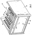
Fig. 1 is a front perspective view of a dispensing cabinet according to the invention. -
Fig. 1A is a detailed view of a portion of a shelf of the cabinet ofFig. 1 . -
Fig. 2 illustrates a pharmaceutical dispensing unit f the cabinet ofFig. 1 -
Fig. 3 illustrates the unit ofFig. 2 having dispensing mechanisms and showing a front door opened. -
Fig. 4 illustrates the unit ofFig. 3 with a dispenser frame having the dispensing mechanisms withdrawn. -
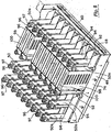
Fig. 5 is a more detailed view of the dispenser frame and dispensing mechanisms ofFig. 4 . -
Fig. 5A illustrates a dispensing coil of one particular dispensing mechanism. -
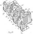
Fig. 5B illustrates a set of dispensing mechanisms according to the invention. -
Fig. 5C is a more detailed view of a cassette type dispensing mechanism according to the invention. -
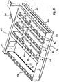
Fig. 6 illustrates the dispenser frame ofFig. 4 with the dispensing mechanisms removed. -
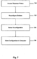
Fig. 7 is a flowchart illustrating one method for reconfiguring the dividers of a dispensing dispenser frame. -
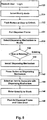
Fig. 8 is a flowchart illustrating one method for assigning items to dispensing mechanisms. -
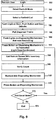
Fig. 9 is a flowchart illustrating one method for restocking items. -
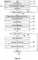
Fig. 10 is a flowchart illustrating one method for dispensing items. - The invention provides exemplary dispensing devices that may easily be reconfigured as well as restocked, among other features. The dispensing devices may have a dispensing unit that is secured within a cabinet, with access being provided to only authorized individuals. The dispensing unit may hold a variety of dispensing mechanisms that each hold items to be dispensed. Such an arrangement is particularly well suited for items that need to be secured, such as medications, drugs, and the like. If a nurse user is authorized, such items may be dispensed from the dispensing unit where they may fall into a dispense drawer that may be pulled from the cabinet to access the items.
- The dispensing unit may include a dispenser frame that holds the dispensing mechanisms. The dispenser frame may also be pulled out from the cabinet to provide access to the dispensing mechanisms. Further, the dispenser frame may include reconfigurable dividers that hold the dispensing mechanisms. In this way, a wide variety of dispensing mechanism arrangements may be provided by reconfiguring the dividers and/or the location of the dispensing mechanisms on the dividers. Further, various types of dispensing mechanisms may be accommodated.
- To reconfigure the unit, the dispenser frame may be withdrawn and the dividers may be reconfigured. Also, the dispensing mechanisms may be plugged into different locations on the dividers. Various sensing or detecting systems may be used to determine the configuration of the dividers and the addresses of the dispensing mechanisms on the dividers so that the computer system may associate items with each of the dispensing mechanisms. For example, when reconfiguring the location of a dispensing mechanism, a sensing mechanism, such as a button, may be pressed on the dispensing mechanism to indicate the new location of the dispensing mechanism. This is in stark contrast to prior art systems where physical address labels have been placed onto each divider. If the configuration of such systems changed, these labels needed to be changed as well.
- Such an arrangement also facilitates initial stocking and restocking. To initially stock a dispensing mechanism, a sensing mechanism, such as a button on the dispensing mechanism, may be pushed to identify the dispensing mechanism. The type and quantity of the item to be stocked may then be entered into the computer. By pressing the button, the computer may detect the dispensing mechanism being accessed and may assigned the item to that address.
- To restock, a restock list may be selected. The dispensing cabinet's computer may be coupled to a network to permit various restock information to be downloaded to the computer. This information may be stored at the computer, or else accessed when needed over the network. Visual indicators, such as lights, LEDs, or the like, on the dispensing mechanisms that are to be restocked may then be actuated to guide the restock user or pharmacist through the restocking process. The button on the dispensing mechanism may be pushed to identify the dispensing mechanism that is being restocked, and the expected quantity may be displayed on the display screen. A count may be verified, the dispensing mechanism restocked, and the quantity entered.
- Referring now to
Fig. 1 , one embodiment of a dispensingcabinet 10 will be described.Cabinet 10 may conveniently be constructed from acabinet frame 12 with varioustransparent panels 14.Cabinet 10 further includes a pair ofdoors shelves 20 withincabinet 10. As also shown inFig. 1A ,shelves 20 may conveniently be divided into various storage locations usingadjustable dividers 22. Further, associated with each storage location may be anitem button 24 that may be pressed to record the removal of items from or placement of items into each storage location. A light 26 may also be positioned adjacent each item button to guide the restock user to a specific storage location. Further, alabel 28 may be associated with each storage location include information on the items stored in a particular storage location. Optionally,doors computer 30. Hence, to remove an item from one of theshelves 20, a nurse user may enter appropriate identification information intocomputer 30. - To facilitate the entry of information,
computer 30 includes atraditional keyboard 32 and akey pad 33 containing numeric keys. A touch pad 33a may be disposed abovekey pad 33 and used to control a pointer on adisplay screen 34. Disposed belowkey pad 33 are keys to control the contrast ofdisplay screen 34 and to control the sound that may be emitted from a speaker 33b. Disposed belowkeyboard 32 is areceipt port 33c through which printed receipts may pass. Conveniently, thepanel containing keyboard 32 may be rotated downward to gain access to the receipt printer. - One use of the various input devices on
computer 30 is to permit the nurse user to select one or more items that are to be removed. Conveniently, a list of items and the entered information may conveniently be displayed on thedisplay screen 34. Further,display screen 34 may be a touch screen display that permits various items to be selected simply by touching them ondisplay screen 34.Computer 30 may be coupled to any type of computer network to permit various information to be supplied tocomputer 30. For example, restock lists may be transmitted from a central server or host computer system. - When the appropriate items have been selected,
doors doors appropriate lights 26 may be lighted to guide the nurse user to the items selected. Upon removal of the items, the nurse user may press item buttons 24 a number of times corresponding to the number of items removed. A similar process may be used for restocking items into the storage locations. A further discussion of such a process is described inU.S. Patent Nos. 6,272,394 ;6,385,505 ;5,805,455 ;5,805,456 ;5,745,366 ;5,905,653 ;5,927,540 ;6,039,467 ;6,151,536 , previously incorporated herein by reference and will not be described further. -
Cabinet 10 further includes apharmacy section 36 withvarious drawers 38 for holding pharmaceutical items or other types of items that need additional security. When appropriate information has been entered intocomputer 30, theappropriate drawers 38 may be unlocked andlights 40 on the drawers lighted to guide the nurse user to the appropriate doors.Drawers 38 may conveniently include various bins which may optionally have lockable lids to provide additional security to the items. The lids corresponding to bins that have the selected items may be unlocked and nurse users may be guided to the unlocked bins using lights in a manner similar to that described withshelves 20. Examples of various types of drawer and bin arrangements that may be used inpharmacy section 36 may be found in at least some ofU.S. Patent Nos. 6,272,394 ;6,385,505 ;5,805,455 ;5,805,456 ;5,745,366 ;5,905,653 ;5,927,540 ;6,039,467 ;6,151,536 , previously incorporated herein by reference, and will not be described further. -
Pharmacy section 36 further includes a dispensingunit 42 that is also illustrated in greater detail with reference toFigs. 2-5 . Briefly, dispensingunit 42 comprises adispensing unit frame 44 that is insertable intocabinet frame 12 ofcabinet 10. Coupled to dispensingunit frame 44 is adoor 46 that may be opened to provide access to a dispenser frame 48 (seeFig. 3 ). As described in greater detail hereinafter,dispenser frame 48 may be withdrawn from dispensingunit frame 44 to provide access to various dispensing mechanisms 50 (see for exampleFigs. 4 and5 ). As best shown inFig. 2 , disposed belowdispenser frame 48 is a dispensedrawer 52 that receives items that fall from dispensingmechanisms 50 after such items have been selected at computer 30 (seeFig. 1 ). Conveniently, dispensedrawer 52 may include a light 54 to guide the nurse user to the dispense drawer during dispensing operations. Conveniently, a handle 56 (seeFigs. 1 and2 ) may be provided ondoor 46 to facilitate opening ofdoor 46. - In some cases, dispensed items may need to be returned to
cabinet 10. In some situations, various laws and regulations prohibit dispensed items from being placed back intocabinet 10. As such, attached tocabinet 10 may be areturn unit 58 having a slidable (or rotatable)door 60 that may be opened to permit the item to be placed intounit 58. When returning the item, information regarding the return may be entered intocomputer 30. Conveniently, a light 62 onreturn unit 58 may be lighted to indicate to the nurse user that the item may be returned.Return unit 58 is preferably configured so that once an item is placed into the unit, the item cannot be returned fromunit 58 unless a restock user or technician is authorized to gain access to returnunit 58. For example, a restock technician may be required to enter appropriate information intocomputer 30 to causereturn unit 58 to unlock to allow access to the items withinreturn unit 58. - Although one specific arrangement of
cabinet 10 has been described, it will be appreciated that dispensingunit 42 may be used with a variety of dispensing cabinets. For example, dispensingunit 42 may be placed within a cabinet that is used solely for dispensing pharmaceuticals and may only include drawers similar todrawers 38. As another alternative, dispensingunit 42 may be placed in a cabinet that only includes shelves that are similar toshelves 20. Further, dispensingunit 42 may be used in cabinets having multiple shelves and/or drawers that are placed side by side in a vertical arrangement. Also, the dispensing cabinet may include multiple dispensingunits 42. These may be sized to the same size, or may be a different size. Still further, in some cases such dispensing cabinets may include other types of shelves, racks, drawers, and the like to facilitate the storage of items. Various examples of shelf, rack, and drawer designs are described inU.S. Patent Nos. 6,272,394 ;6,385,505 ;5,805,455 ;5,805,456 ;5,745,366 ;5,905,653 ;5,927,540 ;6,039,467 ;6,151,536 ;5,377,864 ; and5,190,185 , previously incorporated herein by reference. - Referring now to
Figs. 2-6 , construction and operation of dispensingunit 42 will be described in greater detail. As best shown inFig. 3 ,door 46 is coupled to frame 44 using hinges 64. These permitdoor 46 to be opened to gain access todispenser frame 48. Conveniently,arms 66 may be used to limit the extent to whichdoor 46 may be opened so that it does not interfere with the opening of dispensedrawer 52 as best illustrated inFig. 4 . Conveniently,dispenser frame 48 andframe 44 include atrack system 68 and 70 (and dispensedrawer 52 andframe 44 may also include a similar track system) to permit dispensedrawer 52 anddispenser frame 48 to easily be withdrawn fromframe 44 as shown inFig. 4 . - As best shown in
Fig. 6 ,dispenser frame 48 is constructed of arectangular frame 72 having a front 74, a back 76 and twosides Frame 72 is generally open except for a set ofadjustable dividers 82 that are positioned betweenfront 74 and back 76. Optionally, another divider may be coupled toside 78 as illustrated inFig. 6 . -
Front 74 and back 76 may include a set of mechanical interfaces, such as slots, holes, grooves, cut outs or the like to interface with tabs, protrusions, or the like ondividers 82. In this way, a blind matable connection between thedividers 82 andframe 72 may easily occur. Further, screws 84 may be used to securely coupledividers 82 to frame 72 once in place. By providing a series of mechanical interfaces, the placement ofdividers 82 indispenser frame 48 may be varied alongfront 74 and back 76. Further, any number ofdividers 82 may be coupled todispenser frame 48. In this way, the wide variety of dispensing mechanisms that are to be coupled todividers 82 may be accommodated. Back 76 may also include a series of electrical interfaces that interface with electrical interfaces ondividers 82 when they are mechanically coupled todispenser frame 48.Dispenser frame 48 may also include a circuit board 86 (seeFig. 6 ) that may be used to facilitate communications between circuitry associated with thedividers 82 andcomputer 30. One capability of the circuitry used withcabinet 10 is the ability to detect the specific configuration ofdividers 82 withindispenser frame 48. For example, appropriate circuitry in combination withcomputer 30 may be used to poll each one of the interfaces to determine if one of thedividers 82 is connected to that interface. This may be detected, for example, by sensing a short or low voltage signal that is created whendivider 82 is coupled to a specific electrical interface. - Hence, dispensing
unit 42 may include asingle dispenser frame 48 that has essentially the same width as dispensedrawer 52 that is positioned beneathdispenser frame 48. Further, dispensedrawer 52 may have essentially the same width as other drawers and/or shelves in the dispensing cabinet. In this way, a single dispenser frame may be employed to hold a wide variety of dispensing mechanisms that may all be simultaneously accessed by withdrawingdispenser frame 48. Further, the configuration ofdispenser frame 48 may easily be varied simply by changing the configuration and/or number ofdividers 82 that are included withindispenser frame 48. Further, the configuration ofdividers 82 may be automatically sensed so that the dispensing cabinet will know the configuration of the dividers that will subsequently be needed for dispensing and/or restocking operations as described in greater detail hereinafter. - Each
divider 82 includesmechanical interfaces 88 andelectrical interfaces 90 which are employed to receive dispensingmechanisms 50. As will be appreciated, a wide variety of dispensing mechanisms may be used. For convenience of discussion, the dispensing mechanisms in general will be referred to withreference numeral 50. Specific types of dispensing mechanisms will use the same reference numeral followed by an "a", "b", etc. For example, dispensingmechanisms 50a are syringe type dispensers, and dispensingmechanisms 50b are cassette type dispensers. Conveniently, two dispensingmechanisms 50b may be coupled together to form a double cassette dispenser.Mechanical interfaces 88 may conveniently comprise a threaded opening for receiving a screw. Also, it will be appreciated that other connectors may be used, such as quick release mechanisms, detents, snap fits, other tool-less connections, and the like. As best shown inFig. 4 , dispensingmechanisms 50b are screwed to one of thedividers 82 using ascrew 92.Dispensing mechanism 50b then extends to anadjacent divider 82 to permit anelectrical interface 94 on dispensingmechanism 50b to interface withelectrical interface 90 ofdivider 82. In this way, dispensingmechanisms 50b may be coupled todispenser frame 48 in a "plug and play" manner simply by plugging the dispensing mechanism into the appropriateelectrical interface 90 and then usingscrew 92 to screw the dispensing mechanism tomechanical interface 88. The other dispensing mechanisms may be connected todividers 82 in a similar manner. - As previously described,
dividers 82 may be placed in any configuration to accommodate the number and/or size and/or type ofdispensing mechanism 50 that may be used. For example, although illustrated with several specific types of dispensing mechanisms, it will be appreciated that a wide variety of other dispensing mechanisms may be used that are capable of dispensing items based on an electrical signal that is passed throughelectrical interface 90 viacontrol circuit board 86. Some examples of such dispensing mechanisms that may be used are described inU.S. Patent Nos. 5,377,864 ; and5,190,185 , previously incorporated herein by reference. Hence, it will be appreciated that the invention is not intended to be limited to a specific type of dispensing mechanism. - In order to control dispensing and restock operations, computer 30 (see
Fig. 1 ) needs to know the address of each dispensing mechanism and the type of item stored in that dispensing mechanism. This may easily be accomplished since the location of eachdivider 82 ondispenser frame 48 is automatically determined. In a similar manner, the address for each dispensingmechanism 50 may be determined by using a similar polling process since each dispensing mechanism is electrically coupled to one of thedividers 82. Conveniently, each dispensingmechanism 50 may include abutton 96 that may be pressed by the restock user to produce a detectable event, such as a short or a low-voltage signal that may be detected by a circuit board that is disposed within each divider. The circuit boards are disposed below the connectors and contain address information for each of the dispensing mechanisms. The circuit boards may also be used to control actuation of the dispensing mechanisms and any sensing mechanisms. The address information may be transmitted from the circuit boards tocomputer 30. In this way,computer 30 may know the address of a particular dispensing mechanism whenbutton 96 is pressed. At the same time, the restock user may assign a given item to that particular dispensing mechanism and enter this intocomputer 30 so thatcomputer 30 will have a record of the address of each dispensing mechanism and its associated item. Conveniently, dispensingmechanisms 50 may also includelights 97 that may be used to guide a restock technician to a particular dispensing mechanism during restocking operations as described in greater detail hereinafter. In some cases, the light may be provided on the divider, and the dispensingmechanisms 50 may have a light pipe, such as a plastic conduit, to display the light. In some cases, the dispensing mechanisms may include an identifier that uniquely identifies each dispensing mechanism. This information may be detected by the circuit board and sent tocomputer 30 so thatcomputer 30 may assign a specific dispensing mechanism to a specific location. If the particular dispensing mechanism is removed to another location,computer 30 may detect the displacement and produce a warning signal. Examples of identifiers that may be used include RFID tags, EPROM chips, bar codes and the like. If such identifiers are used, configuration of the dispensing unit may occur automatically sincecomputer 30 will know each specific dispensing mechanism and its location upon connection of the dispensing mechanism. - Referring now to
Figs. 3-5 , construction of dispensingmechanisms 50a will be described. However, as previously set forth,dispenser frame 48 may utilize a wide variety of dispensing mechanisms and the invention is not intended to be limited to a specific type of dispensing mechanism.Dispensing mechanisms 50a each comprise ahousing 98 having anopening 100 that is configured to receive items in a stacked manner. For example, opening 100 may conveniently be used to store syringes. Disposed at the bottom of dispensingmechanism 50a is a dispensing arrangement that is operated by a solenoid to dispense a single item each time the solenoid is operated. Alternatively, dispensing may occur by actuating a motor, other mechanical actuator or the like. Hence, after receiving signals from thecomputer 30, the circuit board within the appropriate divider may be used to send a signal to the appropriate solenoid, motor or other mechanism to cause a dispensing arrangement to operate and dispense a single item. The dispensed item then falls into dispensedrawer 52 that may be pulled fromcabinet 10 to access the dispensed item. A more detailed described of how such a dispensing arrangement may operate is set forth inU.S. Patent Nos. 5,377,864 ; and5,190,185 , previously incorporated herein by reference. - It will be appreciated that other dispensing mechanisms may be used to hold other types of items such as vials, ampoules, cassettes, pills, tablets, other oral solids, and the like. For example, dispensing
mechanisms 50b may be utilized to dispense pill packages, small ampoules, vials, and the like.Dispensing mechanisms 50b include a motor having a vertically oriented output shaft. Coupled to the output shaft is a gear system that is used to rotate ahelical coil 302 surrounding a shaft that is contained within ahousing 305. As best shown inFig. 5A , avial 304 is held incoil 302 and is moved downward whencoil 302 is rotated. Whenvial 304 reaches the bottom ofcoil 302 is it dispensed and falls into dispensedrawer 52. Hence, items may be dispensed from dispensingmechanisms 50b simply by sending an appropriate signal fromcomputer 30 to the motor that rotatescoil 302. - When utilizing other types of dispensing mechanisms,
circuit board 86 may be configured to send other signals to actuate other types of equipment. For example, other types of dispensing mechanisms that may be used are described inFig. 5B . These may conveniently be coupled todividers 82 in a manner similar to that previously described. One of these dispensing mechanisms is a small cassette type dispenser 50c that is similar to dispensingmechanism 50b except for its size. Dispensing mechanism 50c is particularly useful in dispensing pill packages. Another dispensing mechanism is a 5 ml vial dispensing mechanism 50d that is solenoid actuated in a manner similar to dispensingmechanism 50a. Also shown is a 5 mlampoule dispensing mechanism 50e that dispenses 5 ml ampoules using a solenoid in a manner similar to dispensingmechanism 50a. A largecassette dispensing mechanism 50f is employed to dispense pill packages, small ampoules, and vials.Dispensing mechanism 50f may be motor actuated in a manner similar to dispensingmechanism 50b. - Dispensing mechanism 50d is illustrated in greater detail in
Fig. 5C and is constructed of ahousing 300 that houses a solenoid. The solenoid is used to operate a trap door system similar to that described in connection with dispensingmechanism 50a to dispense its contents. As also shown inFig. 5C , dispensing mechanism 50d includes an electrical connector 91 that is configured to be inserted intoconnector 90 when dispensing mechanism 50d is coupled to a divider. - Hence, by utilizing a reconfigurable divider system, and by configuring the divider so that a wide variety of dispensing mechanisms may be interfaced in a plug and play manner,
dispenser frame 48 may be easily configured to accommodate a wide variety of dispensing mechanism types as well as arrangements. The divider configurations may automatically be determined and addresses for each of the dispensing mechanisms may easily be assigned since the appropriate circuitry may easily detect the location of each dispensing mechanism and may supply this information tocomputer 30 where items may be assigned to specific dispensing mechanisms. Although not intended to be limiting, Tables 1-5 below illustrate various types of arrangements that are possible withdispenser frame 48.TABLE 1 Cassette Dispenser Cassette Dispenser Cassette Dispenser Cassette Dispenser Cassette Dispenser Cassette Dispenser Cassette Dispenser Cassette Dispenser Cassette Dispenser Cassette Dispenser Cassette Dispenser Cassette Dispenser Cassette Dispenser Cassette Dispenser Cassette Dispenser Cassette Dispenser Cassette Dispenser Cassette Dispenser Cassette Dispenser Cassette Dispenser Cassette Dispenser Cassette Dispenser Cassette Dispenser Cassette Dispenser Cassette Dispenser Cassette Dispenser Cassette Dispenser Cassette Dispenser Cassette Dispenser Cassette Dispenser Cassette Dispenser Cassette Dispenser Cassette Dispenser Cassette Dispenser Cassette Dispenser Cassette Dispenser Cassette Dispenser Cassette Dispenser Cassette Dispenser Cassette Dispenser Cassette Dispenser Cassette Dispenser Cassette Dispenser Cassette Dispenser Cassette Dispenser - Table 1 describes an arrangement where
dispenser frame 48 is configured to hold a maximum of five cassette-type dispensing mechanisms across the dispenser frame.TABLE 2 Syringe Dispenser Cassette Dispenser Syringe Dispenser Syringe Dispenser Cassette Dispenser Syringe Dispenser Syringe Dispenser Cassette Dispenser Syringe Dispenser Syringe Dispenser Cassette Dispenser Syringe Dispenser Syringe Dispenser Cassette Dispenser Syringe Dispenser Syringe Dispenser Cassette Dispenser Syringe Dispenser Syringe Dispenser Cassette Dispenser Syringe Dispenser Syringe Dispenser Cassette Dispenser Syringe Dispenser Syringe Dispenser Cassette Dispenser Syringe Dispenser - Table 2 shows an arrangement where a dispenser frame may hold a maximum of two syringe-type dispensing mechanisms and one cassette-type dispensing mechanism across the dispenser frame.
TABLE 3 Syringe Dispenser Cassette Dispenser Cassette Dispenser Cassette Dispenser Syringe Dispenser Cassette Dispenser Cassette Dispenser Cassette Dispenser Syringe Dispenser Cassette Dispenser Cassette Dispenser Cassette Dispenser Syringe Dispenser Cassette Dispenser Cassette Dispenser Cassette Dispenser Syringe Dispenser Cassette Dispenser Cassette Dispenser Cassette Dispenser Syringe Dispenser Cassette Dispenser Cassette Dispenser Cassette Dispenser Syringe Dispenser Cassette Dispenser Cassette Dispenser Cassette Dispenser Syringe Dispenser Cassette Dispenser Cassette Dispenser Cassette Dispenser Syringe Dispenser Cassette Dispenser Cassette Dispenser Cassette Dispenser - Table 3 illustrates an arrangement for holding a maximum of one syringe-type dispensing mechanism and three cassette-type dispensing mechanisms across the dispenser frame. The configuration between the syringe-type dispensing mechanisms and cassette-type dispensing mechanisms may be configured by removing and replacing
dividers 82 as previously described.TABLE 4 Top View Syringe Dispenser Cassette Dispenser Syringe Dispenser Syringe Dispenser Cassette Dispenser Syringe Dispenser Syringe Dispenser Cassette Dispenser Syringe Dispenser Syringe Dispenser Cassette Dispenser Syringe Dispenser Syringe Dispenser Cassette Dispenser Syringe Dispenser Cassette Dispenser Cassette Dispenser Cassette Dispenser Syringe Dispenser Cassette Dispenser Cassette Dispenser Cassette Dispenser Syringe Dispenser Cassette Dispenser Cassette Dispenser Cassette Dispenser Syringe Dispenser Cassette Dispenser Cassette Dispenser Cassette Dispenser Syringe Dispenser - Table 4 illustrates a configuration having dividers that define two double wide spaces and one single wide space. The double wide spaces may be used to hold syringe-type dispensers while the single wide spaces may hold cassette-type dispensers. Further, one of the double wide spaces may also be used to hold two cassette-type dispensing mechanisms as well.
TABLE 5 Top View Syringe Dispenser Cassette Dispenser Cassette Dispenser Cassette Dispenser Cassette Dispenser Cassette Dispenser Cassette Dispenser Cassette Dispenser Cassette Dispenser Cassette Dispenser Cassette Dispenser Cassette Dispenser Cassette Dispenser Cassette Dispenser Cassette Dispenser Cassette Dispenser Cassette Dispenser Cassette Dispenser Cassette Dispenser Cassette Dispenser Cassette Dispenser Cassette Dispenser Cassette Dispenser Cassette Dispenser Cassette Dispenser Cassette Dispenser Cassette Dispenser Cassette Dispenser Cassette Dispenser Cassette Dispenser Cassette Dispenser Cassette Dispenser Cassette Dispenser Cassette Dispenser Cassette Dispenser Cassette Dispenser Cassette Dispenser Cassette Dispenser Cassette Dispenser Cassette Dispenser Cassette Dispenser Cassette Dispenser Cassette Dispenser Cassette Dispenser - Table 5 illustrates a dispenser frame configuration having dividers that define one double wide space and three single wide spaces. Further, the double wide space may be configured to hold two cassette-type dispensers in addition to syringe-type dispensers.
- Another feature of dispensing
unit 42 is thatcircuit board 86 is incorporated intodispenser frame 48. In this way,circuit board 86 may easily be accessed for maintenance, repair or replacement simply by withdrawingdispenser frame 48 from dispensingunit 42. Further, incorporatingcircuit board 86 intodispenser frame 48 permits the dividers to be electrically coupled to electrical connectors using a blind matable connection.Circuit board 86 may be a passive connector board that channels commands to other boards used in connection with the dispensing cabinet. These other controllers may be on the same internal communication bus and may be used to filter out communications on non-functioning boards to allow the system to continue operating with a troublesome component.Circuit board 86 may be electrically coupled to another controller (that may in turn be coupled toframe 44 and electrically connected to computer 30) using various ribbon cables or other communication devices. These cables may be routed along the sides of dispensingunit 42 so as to not interfere with travel ofdispenser frame 48 as it is withdrawn and pushed back into dispensingunit 42. The control board onframe 44 may be used as the main controller for operating the components associated with dispensingunit 42. Its functions may include manipulating and distributing power to the components in dispensingunit 42, generating module communications and interacting with the communication bus of the dispensing cabinet, and the like. The communications generated may include, but are not limited to, reading hardware configuration, auto calibrating a dispensing sensor system and running diagnostic scripts. - Various security features may also be provided to dispensing
unit 42. For example, as best shown inFig. 3 ,door 46 may include anopening 108 for receiving a latch of alatching mechanism 109 that may be employed to lockdoor 46 to frame 44. In this way, access todispenser frame 48 may be prevented until appropriate identification information is entered intocomputer 30. After such information has been entered,computer 30 may send a signal to operatelatching mechanism 109 and permitdoor 46 to be unlocked. - Another feature is the use of a sensing system to detect when items have been dispensed from dispensing
mechanisms 50 where they fall into dispensedrawer 52. The sensing mechanism may transmit a beam or other signal below the dispensing mechanisms that may be interrupted as items fall into dispensedrawer 52. One exemplary type of sensing system comprises IR detectors (hidden from view) and emitters 111 (seeFig. 6 ). The IR emitters 111 may be arranged along one of thedividers 82 to emit signals that are directed onto theopposite divider 82 that contains the detectors. In this way, the signal is sent laterally between the dividers. The sensing system may also have an automatic calibration feature for each IR emitter-detector. A calibration may be performed just prior to a dispensing event. Such a calibration may be beneficial in cases where light conditions change over time, such as during a bright day when ambient light enters when the frame is opened. By calibrating just prior to dispensing, the sensing system may be configured to sense the dispensing, even under different lighting conditions. As one alternative, each dispensing mechanism may be associated with it own sensor, including any of those described herein. In this way, each time a particular dispensing mechanism dispenses an item, the sensor may correlate the dispensing with the particular dispensing mechanism. Another way to accomplish such a feature is by using a second set of emitters and detectors that are mounted across the entire length of the dispenser frame (such as betweenfront 74 and back 76 as shown inFig. 6 ). In this way, two sets of emitters and detectors and positioned perpendicular to each other. In this way, the X and Y position of the item may be detected as it is dropped from a dispensing mechanism. This information may be sent tocomputer 30 to indicate the exact dispenser from which the item was dispensed. - Another example of such a sensing system may be a vertical cavity surface emitting laser (VCSEL) sensing system. Such a system comprises a laser that transmits a signal across the bottoms of dispensing
mechanisms 50. The laser is configured to reflect off a micro prism reflector so that the signal may be reflected back to a location near the laser source. If this signal varies, it may be used to detect that an item has been dispensed. Such a sensing system may be a VCSEL laser sensing system, from Honeywell. In this way, a confirmation may be made that an item was in fact dispensed when requested by the nurse user atcomputer 30. Such a sensing system is advantageous in that it reduces calibration times and is able to sense across the entire dispenser frame to reduce or eliminate errors. - Referring now to
Fig. 7 , one method for configuringdividers 82 on dispenser frame 84 will be described. Conveniently, the process illustrated inFig. 7 may be described in connection with the dispensingcabinet 10 and dispensingunit 42 as just described in connection withFigs. 1-6 . Initially, the restock user may log into thesystem using computer 30 andplace computer 30 into the configuration mode. The restock user may then specify a zone that is to receive dispensingunit 42 so that its position withincabinet 10 is known. To configure the dividers, the dispenser frame is accessed as shown instep 120. This may conveniently be accomplished by withdrawingdispenser frame 48 from dispensingunit 42. The dividers may then be reconfigured in the desired position as illustrated instep 122.Control circuit board 86 may then be used to sense the reconfiguration of the dividers as illustrated instep 124. This information is transmitted tocomputer 30 for storage as shown instep 126. Optionally,computer 30 could be configured to allow the restock user to manually input the configuration of the dividers so that a sensing system would not be needed. - Referring now to
Fig. 8 , one method for configuring the dispensing mechanisms withindispenser frame 48 will be described. Initially, the restock user logs in as illustrated instep 128 by entering appropriate information intocomputer 30. The restock user may then select a modify mode atcomputer 30 as illustrated instep 130. Optionally,door 46 on dispensingunit 42 may include abutton 57 that the restock user may push to unlockdoor 46 as illustrated instep 132. In so doing, latchingmechanism 109 operates to unlatch the latch so that restock user may open the door. As shown instep 134, the restock user may then pulldispenser frame 48 out from the dispensing cabinet. As previously described, one feature of the invention is that a single dispenser frame may be employed so that the restock user may conveniently access all of the dividers when reconfiguring the dispensing mechanisms. - Once the dispenser frame is pulled out, the restock user may select a specific dispensing mechanism to modify as shown in
step 136. The type of modification may depend on whether the dispensing mechanism is already coupled to a divider and simply needs to be reassigned a new type of item, or whether the dispensing mechanism is a new dispensing mechanism that is to be coupled to the divider. A query as to this effect is illustrated instep 138. If the dispensing mechanism is a new dispensing mechanism that is to be added to divider, the dispensing mechanism is installed to the divider as illustrated instep 140. As previously described, this may be accomplished by screwing ascrew 92 intomechanical interface 88. As shown instep 142,button 96 may then be pressed to identify tocomputer 30 the specific dispensing mechanism that is being modified. This process is performed for both new and existing dispensing mechanisms.Display screen 34 may then permit the restock user to select an item to associate with the selected dispensing mechanism as illustrated instep 144. Sincecomputer 30 knows the correct dispensing mechanism on a given divider oncebutton 96 is pressed, it may assign that dispensing mechanism the selected item. As shown instep 146, the restock user may also enter the item quantity into the dispensing mechanism. Steps 136-146 may then be repeated to modify other dispensing units. When the process is finished the dispenser frame may be pushed back into the dispensing cabinet and the door closed as illustrated instep 148. - To restock dispensing
cabinet 10, a restock technician logs intocomputer 30 as illustrated instep 150 ofFig. 9 . A restock technician may be required to enter username and password information which is compared against a list of individuals that are authorized to access dispensingunit 42. If accepted, the restock technician may select the restock mode as illustrated instep 152.Computer 30 may have a record of all items stored in dispensingunit 42 along with their quantity. Further,computer 30 may include a restock list that was received from the pharmacy indicating which items are to be restocked, and may also include a quantity to restock. The restock technician may then select a restock list displayed ondisplay screen 34 as illustrated instep 154. - Once a restock list has been selected,
button 57 may light (and may optionally flash) to indicate to the restock technician where restocking should occur.Button 57 may be pressed which causesdoor 46 to unlock as illustrated instep 156.Door 46 may then be opened anddispenser frame 148 pulled out from dispensingunit 42 as illustrated instep 158. Conveniently, alllights 97 on dispensingmechanisms 50 that need to be restocked may flash to guide the restock technician to the dispensing mechanisms that need to be restocked as illustrated instep 160. The restock technician may then select one of the dispensing mechanisms to be restocked and press the associatedbutton 96. This causes the associated light 97 to stop flashing and to continuously light as illustrated instep 162.Display screen 34 oncomputer 30 may also list the item that is associated with the dispensing mechanism that is being restocked as illustrated instep 164. Inventory information associated with the listed item may also be displayed ondisplay screen 34. Optionally, the restock technician may be asked to verify the number of items within dispensingmechanism 50 as illustrated instep 166. To facilitate counting of the items, an "empty dispenser" icon may be selected ondisplay screen 34, and one of thebuttons 96 may be pressed to dispense all of the items. Hence, the restock technician may manually count the items in the dispensing mechanism and enter this information intocomputer 30. If needed, the quantity may be modified and stored incomputer 30. In most cases, however, a count back will not be needed because the sensors detect when items have been dispensed. In cases where an item that was dispensed is not needed (such as when the patient is asleep), the item is still sensed, but may be returned to the side bin. As shown instep 168, the restock technician may then restock the items into dispensingmechanism 50 and enter the appropriate quantity.Button 96 may then be pressed to indicate that restocking of this dispensing mechanism is complete as illustrated instep 170. Conveniently, light 97 may then turn off to indicate restocking is complete. As shown instep 172, the restock technician may then determine whether additional dispensing mechanisms need to be restocked. If so,steps 162 through 170 are repeated. If not, the process ends atstep 174. The restock technician may then push indispenser frame 48 andclose door 46 which then locks. - Hence, restocking may easily occur by simply withdrawing
dispenser frame 48 to gain access to all of the dispensing mechanisms. Further, the restock technician is guided to the specific dispensing mechanisms that need restocking. Conveniently,computer 30 may be coupled to a network so that restocking information may conveniently downloaded to computer 30 (such as from a pharmacy) to facilitate the restocking process. -
Fig. 10 illustrates one exemplary method for dispensing items from dispensingunit 42 ofcabinet 10. Initially, the nurse user logs intocomputer 30 as illustrated instep 176. This may require the nurse user to enter user name and password information to determine whether the nurse user may have access to the items stored in dispensingunit 42. As shown instep 178, a patient's identification information may also be entered.Computer 30 may then be placed into dispensing mode and the nurse user may enter a certain medication to be dispensed as illustrated instep 180. Conveniently, this medication may be selected from a list displayed ondisplay screen 34. The nurse user may also be required to enter a dose as illustrated instep 182. Optionally, the nurse user may also be asked to verify the quantity to dispense. If the nurse user wishes to dispense more than one item, the process proceeds to step 184 wheresteps - In
step 186, theappropriate dispensing mechanisms 50 dispense the appropriate number of medications which fall into dispensedrawer 52. Conveniently, light 54 on dispensedrawer 52 may light to indicate the dispense drawer having the dispensed items as shown instep 188. The nurse user may then pull out dispensedrawer 52 as shownstep 190 and remove the dispensed medication as illustrated instep 192. Finally, dispensedrawer 52 is closed as shown instep 194. - In some circumstances, the nurse user may wish to return one or more items as illustrated in
step 196. If so, the nurse user may select a return mode atcomputer 30 as illustrated instep 198.Light 62 onreturn unit 58 may then light to guide the nurse user to the appropriate location for returning the dispensed items as shown instep 200.Door 60 may then be opened and the item returned as illustrated instep 202. The process then ends atstep 204. - The invention has now been described in detail for purposes of clarity and understanding. However, it will be appreciated that certain changes and modifications may be practiced within the scope of the appended claims.
Claims (35)
- A device for dispensing items, the device comprising:a cabinet (10) having a front, a back, a pair of sides and an interior having a storage area;a plurality of dispensing mechanisms (50) that are configured to hold a plurality of items within the storage area;a visual indicator (97) associated with each of the dispensing mechanisms (50); anda computer (30) that is operably coupled to the dispensing mechanisms (50) and the visual indicators (97);characterized bythe cabinet (10) being constructed from a cabinet frame (12);the device further comprising a dispensing unit (42) having a unit frame (44) that is insertable into the cabinet frame (12), said dispensing unit (42) being secured within said cabinet (10);the unit frame (44) comprising a dispenser frame (48) and a dispense drawer (52) disposed below the dispenser frame (48) such that items dispensed from the dispensing mechanisms (50) which are operably coupled to the dispenser frame (48) fall into the dispense drawer (52);the dispenser frame (48) includinga plurality of dividers (82), the dispenser frame (48) and the unit frame (44) include a track system (68,70) to permit the dispenser frame (48) be withdrawn from said unit frame (44);a lockable door (46) being positioned in front of the dispenser frame (48) and coupled to the unit frame (44);wherein the door (46) is operable to provide access to the dispenser frame (48);the dividers (82) being reconfigurable in a desired position to permit the arrangement of the dispensing mechanisms (50) to be adjusted;a divider sensing system associated with the dispenser frame (48) to sense the configuration of the dividers (82); andthe computer (30) being configured to store information on the configuration of the dividers (82) and to actuate the visual indicators (97) of the dispensing mechanisms (50) that are to be restocked or modified.
- A device as in claim 1, wherein the dispense drawer (52) has a width that is essentially equal to the width of the dispenser frame (48).
- A device as in claim 2, wherein the dispense drawer (52) extends across essentially the entire length of the front, and wherein the computer (30) is configured to send a signal to automatically open the dispense drawer (52) after an item is dispensed from one of the dispensing mechanisms (50).
- A device as in claim 1, wherein the computer (30) further includes a record of items in the cabinet (10), their quantity and their location.
- A device as in claim 4, wherein the computer (30) is configured to permit the selection of an item and to send a signal that is usable by one of the dispensing mechanisms (50) to dispense the selected item.
- A device as in claim 5, wherein the dispense drawer (52) includes a light (54), and wherein the computer (30) is configured to light the dispense drawer light upon selection of the item.
- A device as in claim 4, wherein the computer (30) is configured to receive input on the items held within the dispensing mechanisms (50).
- A device as in claim 7, wherein the dispensing mechanisms (50) each include a sensor mechanism that is actuatable to send a signal to the computer (30) when actuated.
- A device as in claim 8, wherein the sensor mechanisms are each actuatable to indicate to the computer (30) that the associated dispensing mechanism (50) has been flagged to be assigned an item, and wherein the computer (30) is configured to receive an input assigning an item to the flagged dispensing mechanism (50).
- A device as in claim 8, wherein the sensor mechanisms are each actuatable to indicate to the computer (30) that the associated dispensing mechanism (50) is to be restocked.
- A device as in claim 1, wherein the computer (30) includes a record of individuals that may use the dispensing cabinet (10).
- A device as in claim 11, wherein the computer (30) is configured to unlock the door (46) upon entry of appropriate identification information into the computer (30) from an authorized individual.
- A device as in claim 12, wherein the door (46) includes a light, and wherein the computer (30) is configured to light the door light upon receipt of a restocking request.
- A device as in claim 13, wherein the visual indicators (97) comprise lights, and wherein the computer (30) is configured to light the light corresponding to each dispensing mechanism (50) that is to be restocked.
- A device as in claim 14, wherein the computer (30) is configured to display the type of item to be restocked upon pressing of one of the lighted lights.
- A device as in claim 15, wherein the computer (30) is configured to produce a record of restocking and to turn off the light of the associated dispensing mechanism (50) following restocking.
- A device as in claim 1, wherein the dividers (82) include connectors that are configured to interface with connectors on the dispensers.
- A device as in claim 1, wherein the cabinet (10) further includes a return unit (58) that is adapted to receive returned items.
- A device as in claim 1, further comprising a sensor system that is configured to detect when items fall from the dispensing mechanisms (50) and into the dispense drawer (52).
- A device as in claim 1, wherein the dispenser frame (48) further includes a control circuit board (86) that is electrically coupled to the computer (30) and that is configured to be electrically coupled to the dispensing mechanisms (50).
- A device according to claim 20, wherein each dispensing mechanism (50) includes a button (96), which is configured to produce a detectable event when pressed, which is detectable by a circuit board that is disposed within each divider (82).
- A device according to claim 21, wherein the circuit boards contain address information for each of the dispensing mechanisms (50), the computer (30) being configured that the address information is transmitted from a particular dispensing mechanism (50) when the button (96) is pressed.
- A device according to any one of claims 1 to 22, wherein the dispensing mechanism (50) includes an identifier that uniquely identifies each dispensing mechanism (50).
- A device according to claim 23, wherein information about the identifier is detectable by the circuit board which is configured to send the information to the computer (30), which is configured to assign a specific dispensing mechanism (50) to a specific location.
- A device according to claim 24, wherein the identifier is a RFID tag, EPROM chip or bar code.
- A device as in claim 1, further comprising at least one holding drawer having multiple storage locations that are configured to hold additional items.
- A device as in claim 1, further comprising at least one shelf having storage locations that are configured to hold additional items.
- A method for configuring a dispensing device, the method comprising:providing a dispensing device comprising a cabinet (10) having an interior; a plurality of dispensing mechanisms (50) that each hold a plurality of items within the interior; and a computer (30);actuating a sensing mechanism that is associated with one of the dispensing mechanisms (50) that is to be configured to generate a signal;transmitting the signal to the computer (30) to indicate that the dispensing mechanism (50) that is associated with the actuated sensing mechanism is to be configured; andproviding a visual indicator (97) associated with each of the dispensing mechanisms (50);characterized by:using a cabinet (10) being constructed from a cabinet frame (12);providing a dispensing unit (42) having a unit frame (44) that is insertable into the cabinet frame (12), the dispensing unit (42) being secured within said cabinet (10);the unit frame (44) comprising a dispenser frame (48) and a dispense drawer (52) disposed below the dispenser frame (48) such that items dispensed from the dispensing mechanisms (50) which are operably coupled to the dispenser frame (48) fall into the dispense drawer (52);coupling operably the dispenser frame (48) to the cabinet (10),wherein the dispenser frame (48) and the unit frame (44) include a track system (68,70) to permit the dispenser frame (48) be withdrawn from said unit frame (44) andwherein the dispenser frame (48) includes a plurality of dividers (82) for holding the plurality of dispensing mechanisms (50);providing a lockable door (46) being coupled to the unit frame (44) and being positioned in front of the dispenser frame (48), wherein opening of the door (46) allows to access the dispenser frame (48);providing a divider sensing system associated with the dispenser frame (48) to sense the configuration of the dividers (82);arranging the dividers (82) in a desired configuration;providing a signal from the divider sensing system for supplying information on the arrangement of the dividers (82) to the computer (30); andstoring information on the configuration of the dividers (82) in the computer (30) and to actuating the visual indicators (97) of the dispensing mechanisms (50) that are to be restocked or modified.
- A method as in claim 28, further comprising entering into the computer (30) an item to associate with the dispensing mechanism (50) that is associated with the actuated sensing mechanism.
- A method as in claim 28, further comprising restocking an item into the dispensing mechanism (50) that is associated with the actuated sensing mechanism.
- A method as in claim 28, wherein the sensing mechanism is actuated to enter an address of one of the dispensing mechanisms (50) into the computer (30).
- A method as in claim 31, wherein the address is determined by sensing the location of the new dispensing mechanism (50) on the divider (82) when the sensing mechanism is actuated.
- A method as in claim 32, wherein the sensing mechanism comprises a button on the dispensing mechanism (50), and further comprising pressing the button on the dispensing mechanism (50) to enter the address of the dispensing mechanism (50) into the computer (30).
- A method as in claim 29, wherein the item that is to be associated with the dispensing mechanism (50) is entered by selecting an item from a list of items displayed by the computer (30).
- A method as in claim 28, further comprising entering a request into the computer (30) to dispense an item, and operating the dispensing mechanism (50) to dispense the item into the dispense drawer (52).
Applications Claiming Priority (2)
| Application Number | Priority Date | Filing Date | Title |
|---|---|---|---|
| US10/434,724 US6975922B2 (en) | 2003-05-08 | 2003-05-08 | Secured dispensing cabinet and methods |
| PCT/US2004/014210 WO2004102492A2 (en) | 2003-05-08 | 2004-05-07 | Secured dispensing cabinet and methods |
Publications (3)
| Publication Number | Publication Date |
|---|---|
| EP1627320A2 EP1627320A2 (en) | 2006-02-22 |
| EP1627320A4 EP1627320A4 (en) | 2006-07-05 |
| EP1627320B1 true EP1627320B1 (en) | 2017-04-05 |
Family
ID=33416771
Family Applications (1)
| Application Number | Title | Priority Date | Filing Date |
|---|---|---|---|
| EP04751552.3A Active EP1627320B1 (en) | 2003-05-08 | 2004-05-07 | Secured dispensing cabinet and methods |
Country Status (7)
| Country | Link |
|---|---|
| US (3) | US6975922B2 (en) |
| EP (1) | EP1627320B1 (en) |
| JP (1) | JP4598773B2 (en) |
| AU (1) | AU2004239714B2 (en) |
| CA (1) | CA2523129C (en) |
| ES (1) | ES2632292T3 (en) |
| WO (1) | WO2004102492A2 (en) |
Families Citing this family (157)
| Publication number | Priority date | Publication date | Assignee | Title |
|---|---|---|---|---|
| US7366772B2 (en) * | 2001-06-29 | 2008-04-29 | International Business Machines Corporation | Method and apparatus for creating and exposing order status within a supply chain having disparate systems |
| US8770372B2 (en) * | 2012-02-03 | 2014-07-08 | Ellenby Technologies, Inc. | Coin and bill dispensing safe |
| US6847861B2 (en) | 2001-11-30 | 2005-01-25 | Mckesson Automation, Inc. | Carousel product for use in integrated restocking and dispensing system |
| US7228198B2 (en) | 2002-08-09 | 2007-06-05 | Mckesson Automation Systems, Inc. | Prescription filling apparatus implementing a pick and place method |
| AU2003261446A1 (en) * | 2002-08-09 | 2004-02-25 | Mckesson Automation Systems, Inc. | Controller for dispensing products |
| US7052097B2 (en) | 2002-12-06 | 2006-05-30 | Mckesson Automation, Inc. | High capacity drawer with mechanical indicator for a dispensing device |
| US6975922B2 (en) * | 2003-05-08 | 2005-12-13 | Omnicell, Inc. | Secured dispensing cabinet and methods |
| US8195328B2 (en) | 2003-09-19 | 2012-06-05 | Vesta Medical, Llc | Combination disposal and dispensing apparatus and method |
| CA2547246C (en) | 2003-11-26 | 2012-01-17 | Mckesson Automation Inc. | Integrated suite of medical tools |
| US20050171813A1 (en) * | 2004-02-04 | 2005-08-04 | Jordan Mchael L. | System for identifying and sorting orders |
| US7395897B2 (en) * | 2004-04-09 | 2008-07-08 | Vecta Oil & Gas, Ltd. | Accelerated weight drop configurable for use as a shear wave seismic energy source and a method of operation thereof |
| US7146247B2 (en) * | 2004-11-24 | 2006-12-05 | Cerner Innovation, Inc. | Computerized method and system for loading and/or unloading a tray using laser scanning technology |
| US7177721B2 (en) * | 2004-11-24 | 2007-02-13 | Cerner Innovation, Inc. | Computerized method and system for loading and/or unloading a tray having a light grid over a surface thereof |
| US7845041B2 (en) * | 2005-05-03 | 2010-12-07 | Colgate-Palmolive Company | Interactive musical toothbrush |
| US20070023512A1 (en) * | 2005-06-10 | 2007-02-01 | Mckesson Automation Inc. | Inventory management system using rfid tags to aid in dispensing and restocking inventory |
| ITMI20051727A1 (en) | 2005-09-19 | 2007-03-20 | Bottigelli Service S R L | STORAGE AND WITHDRAWAL OF PRODUCT AND ITS MANAGEMENT PROCEDURE |
| US7747347B2 (en) * | 2005-10-03 | 2010-06-29 | Sabal Medical, Inc. | Mobile medication storage and dispensing apparatus |
| WO2007064816A2 (en) | 2005-12-02 | 2007-06-07 | Asd Specialty Healthcare, Inc. D/B/A Amerisourcebergen Specialty Group | System and method for pharmaceutical management and tracking |
| US7630791B2 (en) * | 2005-12-09 | 2009-12-08 | CareFusion 303 Inc. | System and method for storing items and tracking item usage |
| FR2898116B1 (en) * | 2006-03-06 | 2008-05-30 | Arx Sarl | MODULAR DEVICE FOR AUTOMATICALLY DISTRIBUTING AND EJECTING PRODUCTS STORED IN PARALLEL LONGITUDINAL RANGES |
| US8036773B2 (en) | 2006-05-10 | 2011-10-11 | Mckesson Automation Inc. | System, method and corresponding apparatus for storing, retrieving and delivering unit dose blisters |
| US8878676B2 (en) * | 2006-05-16 | 2014-11-04 | Gt Angel, Llc | Healthcare workstations and RFID devices for detecting medication errors |
| US7693603B2 (en) | 2007-01-22 | 2010-04-06 | John David Higham | Pharmaceutical dispensing system with coordinate guidance |
| US8251629B2 (en) * | 2007-02-09 | 2012-08-28 | Cerner Innovation, Inc. | Medication dispensing apparatus |
| US8682466B2 (en) * | 2007-05-04 | 2014-03-25 | Taiwan Semiconductor Manufacturing Company, Ltd. | Automatic virtual metrology for semiconductor wafer result prediction |
| US8009913B2 (en) | 2007-05-29 | 2011-08-30 | Mckesson Automation, Inc. | System, method, apparatus and computer program product for capturing human-readable text displayed on a unit dose package |
| US8738383B2 (en) | 2007-06-07 | 2014-05-27 | Aesynt Incorporated | Remotely and interactively controlling semi-automatic devices |
| US8280550B2 (en) | 2008-06-17 | 2012-10-02 | Omnicell, Inc. | Cabinet with remote integration |
| US8140186B2 (en) * | 2007-06-19 | 2012-03-20 | Omnicell, Inc. | Bin allocation systems, methods, and devices |
| US8403908B2 (en) | 2007-12-17 | 2013-03-26 | Hospira, Inc. | Differential pressure based flow sensor assembly for medication delivery monitoring and method of using the same |
| US8517990B2 (en) | 2007-12-18 | 2013-08-27 | Hospira, Inc. | User interface improvements for medical devices |
| US8006903B2 (en) | 2007-12-28 | 2011-08-30 | Mckesson Automation, Inc. | Proximity-based inventory management system using RFID tags to aid in dispensing and restocking inventory |
| US8094028B2 (en) | 2007-12-28 | 2012-01-10 | Mckesson Automation, Inc. | Radio frequency alignment object, carriage and associated method of storing a product associated therewith |
| US20090169138A1 (en) * | 2007-12-28 | 2009-07-02 | Mckesson Automation Inc. | Medication and medical supply storage package and method |
| US20090194987A1 (en) * | 2008-01-31 | 2009-08-06 | Mckesson Automation Inc. | Method, apparatus and medication storage device for efficiently generating medication labels |
| US7992746B2 (en) * | 2008-02-11 | 2011-08-09 | Carefusion 303, Inc. | Method and apparatus for removing, inserting and securing receptacles in a receptacle tray |
| US11264124B2 (en) | 2008-02-20 | 2022-03-01 | Chudy Group, LLC | System and apparatus for item management |
| US8380346B2 (en) | 2008-02-20 | 2013-02-19 | Chundy Group, LLC | System and apparatus for item management |
| ES2328656B1 (en) * | 2008-05-14 | 2010-05-25 | Microtiker, S.L | INSTALLATION FOR THE AUTOMATIC DISPENSING AND SEMIAUTOMATIC REPOSITIONING OF COMMERCIAL PRODUCTS. |
| US8065924B2 (en) * | 2008-05-23 | 2011-11-29 | Hospira, Inc. | Cassette for differential pressure based medication delivery flow sensor assembly for medication delivery monitoring and method of making the same |
| US7819838B2 (en) * | 2008-09-02 | 2010-10-26 | Hospira, Inc. | Cassette for use in a medication delivery flow sensor assembly and method of making the same |
| US20100114027A1 (en) * | 2008-11-05 | 2010-05-06 | Hospira, Inc. | Fluid medication delivery systems for delivery monitoring of secondary medications |
| US8588966B2 (en) | 2009-01-09 | 2013-11-19 | Automed Technologies, Inc. | Cabinet system |
| US8103379B2 (en) * | 2009-01-09 | 2012-01-24 | Automed Technologies, Inc. | Medication cabinetry |
| US8744621B2 (en) | 2009-01-09 | 2014-06-03 | Automed Technologies, Inc. | Medical cabinet access belt optimization system |
| US9121197B2 (en) | 2009-01-09 | 2015-09-01 | Automed Technologies, Inc. | Cabinet system with improved drawer security |
| US20100179890A1 (en) * | 2009-01-14 | 2010-07-15 | Cianciotto Jr Michael S | Tool inventory management system |
| US8484049B2 (en) * | 2009-01-30 | 2013-07-09 | Omnicell, Inc. | Tissue tracking |
| US8048022B2 (en) * | 2009-01-30 | 2011-11-01 | Hospira, Inc. | Cassette for differential pressure based medication delivery flow sensor assembly for medication delivery monitoring and method of making the same |
| US8386275B2 (en) | 2009-02-10 | 2013-02-26 | Timothy Chambers | Automatic pill dispensing device and method of use thereof |
| US7982612B2 (en) | 2009-02-20 | 2011-07-19 | Mckesson Automation Inc. | Methods, apparatuses, and computer program products for monitoring a volume of fluid in a flexible fluid bag |
| US9149405B2 (en) | 2009-03-03 | 2015-10-06 | Aesynt Incorporated | Medication storage and dispensing unit having a vial dispenser |
| US8929641B2 (en) | 2009-03-17 | 2015-01-06 | Aesynt Incorporated | System and method for determining the orientation of a unit dose package |
| US8405875B2 (en) | 2009-03-23 | 2013-03-26 | Mckesson Automation Inc. | Visibly-coded medication label and associated method, apparatus and computer program product for providing same |
| US20100249997A1 (en) | 2009-03-25 | 2010-09-30 | Greyshock Shawn T | System, method and corresponding apparatus for detecting perforations on a unit dose blister card |
| US8400277B2 (en) | 2009-03-30 | 2013-03-19 | Mckesson Automation Inc. | Methods, apparatuses, and computer program products for monitoring a transfer of fluid between a syringe and a fluid reservoir |
| US20100263947A1 (en) * | 2009-04-20 | 2010-10-21 | Chris John Reichart | Method for generating electricity from solar panels for an electrical system inside a truck/semi/vehicle |
| US20100280486A1 (en) * | 2009-04-29 | 2010-11-04 | Hospira, Inc. | System and method for delivering and monitoring medication |
| US8267491B2 (en) * | 2009-05-07 | 2012-09-18 | Hotel Outsource Management International, Inc. | Vending machine compartment assembly |
| EP2255774A1 (en) * | 2009-05-25 | 2010-12-01 | Wiegand AG | Medicine dispenser |
| DE102009042891A1 (en) * | 2009-09-24 | 2011-03-31 | Giesecke & Devrient Gmbh | Container and system for processing banknotes |
| US8644982B2 (en) | 2009-09-30 | 2014-02-04 | Mckesson Automation Inc. | Unit dose packaging and associated robotic dispensing system and method |
| ES2335470B1 (en) | 2009-10-14 | 2010-09-27 | Grifols, S.A. | ELECTRONIC SYSTEM FOR THE MANAGEMENT OF REPLACEMENT OR FILLING OF PLANT STORES IN HOSPITALS. |
| US8869667B2 (en) | 2009-12-04 | 2014-10-28 | Aesynt Incorporated | System, method and corresponding apparatus for singulating a unit dose blister card |
| US20110161108A1 (en) * | 2009-12-30 | 2011-06-30 | Mckesson Automation Inc. | Systems and methods for detecting diversion in drug dispensing |
| US8746908B2 (en) | 2010-01-27 | 2014-06-10 | Automed Technologies, Inc. | Medical supply cabinet with lighting features |
| US8453548B2 (en) | 2010-03-23 | 2013-06-04 | Mckesson Automation Inc. | Apparatuses for cutting a unit dose blister card |
| US8640586B2 (en) | 2010-03-23 | 2014-02-04 | Mckesson Automation Inc. | Method and apparatus for facilitating cutting of a unit dose blister card |
| US8593278B2 (en) | 2010-03-29 | 2013-11-26 | Mckesson Automation Inc. | Medication storage device usage status notifications |
| US8527090B2 (en) | 2010-03-30 | 2013-09-03 | Mckesson Automation Inc. | Method, computer program product and apparatus for facilitating storage and/or retrieval of unit dose medications |
| US8660687B2 (en) | 2010-03-30 | 2014-02-25 | Mckesson Automation Inc. | Medication bin having an electronic display and an associated method and computer program product |
| US8474691B2 (en) | 2010-03-31 | 2013-07-02 | Mckesson Automation Inc. | System, apparatus, method and computer-readable storage medium for generating medication labels |
| US20120012606A1 (en) | 2010-07-14 | 2012-01-19 | Mark Longley | Automated pharmacy system for dispensing unit doses of pharmaceuticals and the like |
| US8694162B2 (en) | 2010-12-20 | 2014-04-08 | Mckesson Automation, Inc. | Methods, apparatuses and computer program products for utilizing near field communication to guide robots |
| US8662606B2 (en) | 2011-03-17 | 2014-03-04 | Mckesson Automation Inc. | Drawer assembly and associated method for controllably limiting the slideable extension of a drawer |
| US8701931B2 (en) | 2011-03-30 | 2014-04-22 | Aesynt Incorporated | Medication dispensing cabinet and associated drawer assembly having pockets with controllably openable lids |
| US8588964B2 (en) | 2011-03-30 | 2013-11-19 | Mckesson Automation Inc. | Storage devices, systems, and methods for dispensing medications |
| US8554365B2 (en) | 2011-03-31 | 2013-10-08 | Mckesson Automation Inc. | Storage devices, systems, and methods for facilitating medication dispensing and restocking |
| US9412217B2 (en) | 2011-03-31 | 2016-08-09 | Aesynt Incorporated | Medication dispensing apparatus having conveyed carriers |
| WO2012151332A1 (en) | 2011-05-02 | 2012-11-08 | Omnicell, Inc. | Facility-wide medication management systems |
| US9042607B2 (en) | 2011-05-02 | 2015-05-26 | Omnicell, Inc. | System and method for user access of dispensing unit |
| US9355220B2 (en) | 2011-05-02 | 2016-05-31 | Omnicell, Inc. | Medication dispensing cabinet systems and methods |
| US9355219B2 (en) | 2011-05-02 | 2016-05-31 | Omnicell, Inc. | Dispensing cabinet with articulating arm |
| US8670864B2 (en) | 2011-06-27 | 2014-03-11 | Cerner Innovation, Inc. | Dynamic refill level for medication dispensing apparatus |
| US9240002B2 (en) | 2011-08-19 | 2016-01-19 | Hospira, Inc. | Systems and methods for a graphical interface including a graphical representation of medical data |
| US9910965B2 (en) | 2011-09-16 | 2018-03-06 | Aesynt Incorporated | Systems, methods and computer program product for monitoring interactions with a medication storage device |
| US9471750B2 (en) | 2011-09-23 | 2016-10-18 | Aesynt Incorporated | Systems, methods and computer program product for streamlined medication dispensing |
| US8700210B2 (en) | 2011-09-29 | 2014-04-15 | Aesynt Incorporated | Systems, methods and computer program products for visually emphasizing portions of a medication storage device |
| US8650042B2 (en) | 2011-09-30 | 2014-02-11 | Mckesson Automation Inc. | Case and medication tracking |
| US10022498B2 (en) | 2011-12-16 | 2018-07-17 | Icu Medical, Inc. | System for monitoring and delivering medication to a patient and method of using the same to minimize the risks associated with automated therapy |
| US8983655B2 (en) | 2012-03-26 | 2015-03-17 | Aesynt Incorporated | Automated dispensing system and method |
| US9443370B2 (en) | 2012-03-26 | 2016-09-13 | Omnicare, Inc. | Method and apparatus for onsite distribution of medications and medical supplies |
| US8755930B2 (en) | 2012-03-30 | 2014-06-17 | Aesynt Incorporated | Method, apparatus, and computer program product for optimization of item location in an automated storage system |
| JP6306566B2 (en) | 2012-03-30 | 2018-04-04 | アイシーユー・メディカル・インコーポレーテッド | Air detection system and method for detecting air in an infusion system pump |
| US8807389B2 (en) | 2012-03-30 | 2014-08-19 | Aesynt Incorporated | Item dispensing unit |
| US10045909B2 (en) | 2012-03-30 | 2018-08-14 | Aesynt Incorporated | Storage apparatus with support structures |
| US20130282171A1 (en) * | 2012-04-18 | 2013-10-24 | Jvm Co., Ltd. | Medicine storage apparatus |
| US8869364B2 (en) | 2012-06-25 | 2014-10-28 | Aesynt Incorporated | Material separating tool |
| US9123195B2 (en) | 2012-06-29 | 2015-09-01 | Aesynt Incorporated | Modular, multi-orientation conveyor |
| US9171246B2 (en) | 2012-06-29 | 2015-10-27 | Aesynt Incorporated | System, methods, apparatuses, and computer program products for detecting that an object has been accessed |
| US10360751B2 (en) * | 2012-07-23 | 2019-07-23 | Pharmadva, LLC | Object dispenser having a variable orifice and image identification |
| CA3089257C (en) | 2012-07-31 | 2023-07-25 | Icu Medical, Inc. | Patient care system for critical medications |
| CN104798115B (en) * | 2012-09-28 | 2018-02-02 | 创新产品成就公司 | Article dispensing device |
| CN103158979A (en) * | 2012-10-11 | 2013-06-19 | 苏州艾隆科技股份有限公司 | Medicine outlet machine |
| US20140108027A1 (en) | 2012-10-12 | 2014-04-17 | Mckesson Automation Inc. | Apparatuses, systems, and methods for delivering medications from a central pharmacy to a patient in a healthcare facility |
| US9150119B2 (en) | 2013-03-15 | 2015-10-06 | Aesynt Incorporated | Apparatuses, systems, and methods for anticipating and delivering medications from a central pharmacy to a patient using a track based transport system |
| BR112015011514B1 (en) | 2012-11-19 | 2022-01-25 | Omnicell, Inc | Cabinet system and method for monitoring items having an RFID tag |
| US9814828B2 (en) | 2013-03-15 | 2017-11-14 | Aesynt Incorporated | Method and apparatus for preparing and monitoring an intravenous fluid bag |
| US9443371B2 (en) | 2013-03-27 | 2016-09-13 | Aesynt Incorporated | Medication dispensing cabinet, computing device and associated method for measuring the force applied to a drawer |
| US9884695B2 (en) | 2013-03-28 | 2018-02-06 | Aesynt Incorporated | Compartment configured for presentation of stored articles |
| US9195803B2 (en) | 2013-03-28 | 2015-11-24 | Aesynt Incorporated | Systems, methods, apparatuses, and computer program products for providing controlled access to intravenous bags |
| US9626817B2 (en) | 2013-03-29 | 2017-04-18 | Aesynt Incorporated | Apparatuses, systems, and methods for storing and dispensing medication proximate a patient |
| AU2014268355B2 (en) | 2013-05-24 | 2018-06-14 | Icu Medical, Inc. | Multi-sensor infusion system for detecting air or an occlusion in the infusion system |
| EP3003441B1 (en) | 2013-05-29 | 2020-12-02 | ICU Medical, Inc. | Infusion system which utilizes one or more sensors and additional information to make an air determination regarding the infusion system |
| ES2845748T3 (en) | 2013-05-29 | 2021-07-27 | Icu Medical Inc | Infusion system and method of use that prevent oversaturation of an analog-digital converter |
| US20150076973A1 (en) * | 2013-09-19 | 2015-03-19 | Donald A. PIERSON | Furniture for and method of dispensing diapers |
| US20150088306A1 (en) | 2013-09-26 | 2015-03-26 | Sonia Varrasso | Inventory monitoring system |
| US20150133861A1 (en) | 2013-11-11 | 2015-05-14 | Kevin P. McLennan | Thermal management system and method for medical devices |
| US10984901B1 (en) | 2013-12-18 | 2021-04-20 | Stuart Renwick Locklear | Method and system to implement medical information tracking system and medication dispenser |
| US9365315B2 (en) | 2014-01-28 | 2016-06-14 | Omnicell, Inc. | Versatile lighting system for dispensing cabinets |
| AU2015222800B2 (en) | 2014-02-28 | 2019-10-17 | Icu Medical, Inc. | Infusion system and method which utilizes dual wavelength optical air-in-line detection |
| AU2015266706B2 (en) | 2014-05-29 | 2020-01-30 | Icu Medical, Inc. | Infusion system and pump with configurable closed loop delivery rate catch-up |
| US10143795B2 (en) | 2014-08-18 | 2018-12-04 | Icu Medical, Inc. | Intravenous pole integrated power, control, and communication system and method for an infusion pump |
| CN104443982B (en) * | 2014-10-30 | 2016-08-24 | 江苏迅捷装具科技有限公司 | Ethical goods caching rapid medicine dispensing system and method |
| US11344668B2 (en) | 2014-12-19 | 2022-05-31 | Icu Medical, Inc. | Infusion system with concurrent TPN/insulin infusion |
| US9818251B2 (en) | 2015-02-27 | 2017-11-14 | Omnicell, Inc. | Unit dose dispensing systems and methods |
| US10850024B2 (en) | 2015-03-02 | 2020-12-01 | Icu Medical, Inc. | Infusion system, device, and method having advanced infusion features |
| CA2987011A1 (en) | 2015-05-26 | 2016-12-01 | Icu Medical, Inc. | Disposable infusion fluid delivery device for programmable large volume drug delivery |
| RU2597456C1 (en) * | 2015-08-21 | 2016-09-10 | Кирилл Эдуардович Пищик | Vending machine for remote selling and method of remote selling controlled goods |
| US10427819B2 (en) | 2015-08-25 | 2019-10-01 | Chudy Group, LLC | Plural-mode automatic medicament packaging system |
| US10515722B2 (en) | 2015-10-15 | 2019-12-24 | Omnicell, Inc. | Medical equipment with diversion mechanism |
| US10685091B1 (en) * | 2016-02-02 | 2020-06-16 | PharmRight Corporation | System and method for dispensing pharmaceutical doses |
| US10186100B2 (en) | 2016-02-09 | 2019-01-22 | Omnicell, Inc. | Relay box |
| WO2017197024A1 (en) | 2016-05-13 | 2017-11-16 | Icu Medical, Inc. | Infusion pump system and method with common line auto flush |
| WO2017214441A1 (en) | 2016-06-10 | 2017-12-14 | Icu Medical, Inc. | Acoustic flow sensor for continuous medication flow measurements and feedback control of infusion |
| US10517799B2 (en) | 2017-08-31 | 2019-12-31 | Omnicell, Inc. | Unit dose dispensing mechanisms |
| US11735304B2 (en) | 2017-09-26 | 2023-08-22 | Mckesson Corporation | Robotic dispensary system and methods |
| US10358247B2 (en) | 2017-10-27 | 2019-07-23 | Chudy Group, LLC | Compartmentalized container loading and management system |
| US11536506B2 (en) | 2018-09-12 | 2022-12-27 | Omnicell, Inc. | Temperature controlled dispense drawer |
| US10663218B2 (en) | 2017-11-17 | 2020-05-26 | Omnicell, Inc. | Dispensing system with temperature controlled drawers |
| US10089055B1 (en) | 2017-12-27 | 2018-10-02 | Icu Medical, Inc. | Synchronized display of screen content on networked devices |
| US11348672B2 (en) | 2017-12-29 | 2022-05-31 | Cerner Innovation, Inc. | Medical order entry integration with automated dispensing systems |
| WO2019143734A1 (en) * | 2018-01-17 | 2019-07-25 | Zanghi Robert Joseph | Improvements to supply chain security |
| US10806676B2 (en) | 2018-01-30 | 2020-10-20 | Omnicell, Inc. | Relay tray |
| CN108986316A (en) * | 2018-07-24 | 2018-12-11 | 吉林工程技术师范学院 | A kind of automatic vending machine |
| EP3853675A4 (en) * | 2018-09-20 | 2022-07-27 | SupplyPro, Inc. | Modular storage system apparatus and methods |
| CN110013409B (en) * | 2019-04-28 | 2020-08-28 | 漯河医学高等专科学校 | A medicine feeding device for gynaecology and obstetrics's nursing |
| CN110322638A (en) * | 2019-08-14 | 2019-10-11 | 山东便利客智能科技有限公司 | A kind of automatic medicine selling machine |
| USD939079S1 (en) | 2019-08-22 | 2021-12-21 | Icu Medical, Inc. | Infusion pump |
| US11426329B2 (en) | 2019-11-12 | 2022-08-30 | Omnicell, Inc. | Dispensing systems and methods for prefilled syringes |
| US11278671B2 (en) | 2019-12-04 | 2022-03-22 | Icu Medical, Inc. | Infusion pump with safety sequence keypad |
| US11505354B1 (en) | 2020-02-19 | 2022-11-22 | Nelson Irrigation Coporation | Packaging/inspection system for a nozzle pivot package |
| EP4185260A1 (en) | 2020-07-21 | 2023-05-31 | ICU Medical, Inc. | Fluid transfer devices and methods of use |
| CN112082306A (en) * | 2020-09-08 | 2020-12-15 | 枣庄市妇幼保健院 | Multifunctional pharmacy medicine dispensing cabinet |
| US11135360B1 (en) | 2020-12-07 | 2021-10-05 | Icu Medical, Inc. | Concurrent infusion with common line auto flush |
| WO2023170680A1 (en) | 2022-03-08 | 2023-09-14 | Equashield Medical Ltd | Fluid transfer station in a robotic pharmaceutical preparation system |
| CN116552967B (en) * | 2023-07-11 | 2023-09-19 | 佳木斯大学 | Frame is accomodate with antiseptic solution to clinical branch of academic or vocational study of medical treatment |
Citations (2)
| Publication number | Priority date | Publication date | Assignee | Title |
|---|---|---|---|---|
| WO1998026746A2 (en) * | 1996-12-05 | 1998-06-25 | Omnicell Technologies, Inc. | Replacement liner and methods for dispensing device |
| EP1053738A2 (en) * | 1999-05-20 | 2000-11-22 | SANYO ELECTRIC Co., Ltd. | Solid preparation filling Apparatus |
Family Cites Families (51)
| Publication number | Priority date | Publication date | Assignee | Title |
|---|---|---|---|---|
| US2606803A (en) | 1948-04-30 | 1952-08-12 | Craig Machine Inc | Vending machine |
| US2653850A (en) | 1949-11-17 | 1953-09-29 | Theodore F Vollten | Combination storage and dispensing rack |
| US3437238A (en) | 1967-08-28 | 1969-04-08 | Marion J Luba | Automatic butter dispenser |
| US4062385A (en) | 1975-03-14 | 1977-12-13 | Eastman Kodak Company | Toner handling apparatus |
| US3998356A (en) | 1975-08-28 | 1976-12-21 | Arthur A. Bennett, Jr. | Electronic system for article dispensing apparatus |
| US4225056A (en) | 1978-09-28 | 1980-09-30 | Artag Plastics Corporation | Computerized vending machine |
| US4267942A (en) | 1979-06-20 | 1981-05-19 | John B. Wick, Jr. | Pharmaceutical dispensing cabinet |
| US4360125A (en) | 1980-03-10 | 1982-11-23 | Medtronic, Inc. | Medication inventory device |
| US4519522A (en) | 1981-07-06 | 1985-05-28 | Photo Vending Corporation | Apparatus and method for storing and retrieving articles |
| DE3233559C2 (en) | 1982-09-10 | 1984-11-29 | Agfa-Gevaert Ag, 5090 Leverkusen | Device for the light-tight introduction of a stacked film container |
| GB8323810D0 (en) | 1983-09-06 | 1983-10-05 | Banks E J K | Supervising access to individual items |
| US4573606A (en) | 1983-09-12 | 1986-03-04 | Kermit E. Lewis | Automatic pill dispenser and method of administering medical pills |
| US4572403A (en) | 1984-02-01 | 1986-02-25 | Rafael Benaroya | Timed dispensing device for tablets, capsules, and the like |
| US4663621A (en) | 1984-03-30 | 1987-05-05 | Field David J | Medicine cabinet |
| US4695954A (en) | 1984-10-31 | 1987-09-22 | Rose Robert J | Modular medication dispensing system and apparatus utilizing portable memory device |
| JPS6392984U (en) | 1986-12-05 | 1988-06-15 | ||
| US4814592A (en) | 1986-05-29 | 1989-03-21 | Videomat Associates | Apparatus and method for storing and retrieving articles |
| DE3702407A1 (en) | 1986-11-06 | 1988-05-11 | Nsm Apparatebau Gmbh Kg | RENTAL AND SALES MACHINE, ESPECIALLY FOR VIDEO CASSETTE, AND CASSETTE BOX FOR VIDEO CASSETTE |
| US4785969A (en) | 1986-11-10 | 1988-11-22 | Pyxis Corporation | Medication dispensing system |
| SE457917B (en) | 1987-05-19 | 1989-02-06 | Electrolux Ab | CABINET FOR SELLING DIFFERENT ARTICLES LOCATED IMAGASIN, WHICH IS LOADABLE FIXABLE IN POCKETS IN THE CABINET |
| US4847764C1 (en) | 1987-05-21 | 2001-09-11 | Meditrol Inc | System for dispensing drugs in health care instituions |
| US4811764A (en) | 1987-10-19 | 1989-03-14 | Mclaughlin John T | Medication dispenser station |
| SU1698598A1 (en) * | 1987-12-11 | 1991-12-15 | В.А. Васильев | Household refrigerator |
| US4967928A (en) | 1988-06-09 | 1990-11-06 | Carter Cheryl L | Inventory control including individual patient listing and medical chart record for medication cart |
| JP3362225B2 (en) | 1989-05-25 | 2003-01-07 | バクスター・インターナショナル・インコーポレーテッド | Drug supply device |
| US5267174A (en) | 1989-09-29 | 1993-11-30 | Healthtech Services Corp. | Interactive medication delivery system |
| US5190185A (en) | 1990-05-18 | 1993-03-02 | Baxter International Inc. | Medication transport and dispensing magazine |
| JP3468790B2 (en) | 1993-01-19 | 2003-11-17 | 健 柳沢 | Transfer device |
| US5912818A (en) * | 1993-01-25 | 1999-06-15 | Diebold, Incorporated | System for tracking and dispensing medical items |
| US5790409A (en) | 1993-01-25 | 1998-08-04 | Medselect Systems, Inc. | Inventory monitoring and dispensing system for medical items |
| JP3354219B2 (en) * | 1993-07-07 | 2002-12-09 | 三洋電機株式会社 | Chemical storage |
| US6385505B1 (en) | 1993-07-21 | 2002-05-07 | Omnicell.Com | Methods and apparatus for dispensing items |
| US6272394B1 (en) | 1993-07-21 | 2001-08-07 | Omnicell.Com | Methods and apparatus for dispensing items |
| US5431299A (en) | 1994-01-26 | 1995-07-11 | Andrew E. Brewer | Medication dispensing and storing system with dispensing modules |
| US5745366A (en) | 1994-07-14 | 1998-04-28 | Omnicell Technologies, Inc. | Pharmaceutical dispensing device and methods |
| US5905653A (en) | 1994-07-14 | 1999-05-18 | Omnicell Technologies, Inc. | Methods and devices for dispensing pharmaceutical and medical supply items |
| US5805456A (en) | 1994-07-14 | 1998-09-08 | Omnicell Technologies, Inc. | Device and method for providing access to items to be dispensed |
| US6760643B2 (en) * | 1994-10-11 | 2004-07-06 | Omnicell, Inc. | Methods and apparatus for dispensing items |
| JP2933837B2 (en) * | 1994-10-21 | 1999-08-16 | 株式会社湯山製作所 | Drug packaging device |
| US5797515A (en) * | 1995-10-18 | 1998-08-25 | Adds, Inc. | Method for controlling a drug dispensing system |
| DE19728885C2 (en) * | 1997-07-07 | 2000-10-19 | Reinhard Albers | Computer-based loan system |
| US5927540A (en) | 1997-08-20 | 1999-07-27 | Omnicell Technologies, Inc. | Controlled dispensing system and method |
| US6062438A (en) * | 1998-04-20 | 2000-05-16 | Mars, Inc. | Apparatus for dispensing of bulk product |
| US6151536A (en) | 1998-09-28 | 2000-11-21 | Omnicell.Com | Dispensing system and methods |
| US6564121B1 (en) * | 1999-09-22 | 2003-05-13 | Telepharmacy Solutions, Inc. | Systems and methods for drug dispensing |
| US6658322B1 (en) * | 2000-05-05 | 2003-12-02 | Medselect Inc. | System and method for tracking medical items and supplies |
| WO2003074396A1 (en) * | 2002-03-04 | 2003-09-12 | Alexandre Maldonado | Adjustable push forward dispensing mechanism |
| JP2002156181A (en) * | 2000-11-16 | 2002-05-31 | Yozan Inc | Refrigerator |
| JP4617011B2 (en) * | 2001-03-13 | 2011-01-19 | 株式会社湯山製作所 | Drug storage device |
| JP2002282342A (en) * | 2001-03-26 | 2002-10-02 | Naka Instruments Co Ltd | Drug controlling system |
| US6975922B2 (en) | 2003-05-08 | 2005-12-13 | Omnicell, Inc. | Secured dispensing cabinet and methods |
-
2003
- 2003-05-08 US US10/434,724 patent/US6975922B2/en not_active Expired - Lifetime
-
2004
- 2004-05-07 ES ES04751552.3T patent/ES2632292T3/en active Active
- 2004-05-07 CA CA2523129A patent/CA2523129C/en active Active
- 2004-05-07 AU AU2004239714A patent/AU2004239714B2/en active Active
- 2004-05-07 JP JP2006532834A patent/JP4598773B2/en active Active
- 2004-05-07 EP EP04751552.3A patent/EP1627320B1/en active Active
- 2004-05-07 WO PCT/US2004/014210 patent/WO2004102492A2/en active Application Filing
-
2005
- 2005-08-17 US US11/206,660 patent/US7571024B2/en not_active Expired - Lifetime
-
2009
- 2009-07-02 US US12/496,746 patent/US7835819B2/en not_active Expired - Lifetime
Patent Citations (2)
| Publication number | Priority date | Publication date | Assignee | Title |
|---|---|---|---|---|
| WO1998026746A2 (en) * | 1996-12-05 | 1998-06-25 | Omnicell Technologies, Inc. | Replacement liner and methods for dispensing device |
| EP1053738A2 (en) * | 1999-05-20 | 2000-11-22 | SANYO ELECTRIC Co., Ltd. | Solid preparation filling Apparatus |
Also Published As
| Publication number | Publication date |
|---|---|
| CA2523129C (en) | 2013-01-29 |
| EP1627320A4 (en) | 2006-07-05 |
| AU2004239714B2 (en) | 2011-02-03 |
| CA2523129A1 (en) | 2004-11-25 |
| WO2004102492A3 (en) | 2005-08-18 |
| US6975922B2 (en) | 2005-12-13 |
| US20060085094A1 (en) | 2006-04-20 |
| JP2007502191A (en) | 2007-02-08 |
| WO2004102492A2 (en) | 2004-11-25 |
| JP4598773B2 (en) | 2010-12-15 |
| EP1627320A2 (en) | 2006-02-22 |
| ES2632292T3 (en) | 2017-09-12 |
| AU2004239714A1 (en) | 2004-11-25 |
| US20100070074A1 (en) | 2010-03-18 |
| US7571024B2 (en) | 2009-08-04 |
| US20040225409A1 (en) | 2004-11-11 |
| US7835819B2 (en) | 2010-11-16 |
Similar Documents
| Publication | Publication Date | Title |
|---|---|---|
| EP1627320B1 (en) | Secured dispensing cabinet and methods | |
| US6788997B1 (en) | Medical cabinet with adjustable drawers | |
| US6112502A (en) | Restocking method for medical item dispensing system | |
| US5912818A (en) | System for tracking and dispensing medical items | |
| EP3373883B1 (en) | A medical technology station and method of use | |
| EP3261496B1 (en) | Unit dose dispensing systems and methods | |
| US5848593A (en) | System for dispensing a kit of associated medical items | |
| US5993046A (en) | System for dispensing medical items by brand or generic name | |
| US8423180B1 (en) | System for tracking and dispensing medical items from environmentally controlled storage area | |
| US5745366A (en) | Pharmaceutical dispensing device and methods | |
| US7085621B2 (en) | Method of operating a dispensing cabinet | |
| US6108588A (en) | Restocking method for medical item dispensing system | |
| US6163737A (en) | Medical item dispensing apparatus | |
| US7689317B2 (en) | Medical item inventory monitoring system with automatic electronic reordering | |
| US7596426B2 (en) | Method of monitoring medical item inventory | |
| US20030105554A1 (en) | Dispensing cabinet with unit dose dispensing drawer | |
| EP0749617A1 (en) | Medication administration system with medication dispensing and storing modules | |
| EP0954800B1 (en) | Pharmaceutical dispensing device and methods | |
| AU728806B2 (en) | Pharmaceutical dispensing device and methods | |
| US11426329B2 (en) | Dispensing systems and methods for prefilled syringes | |
| WO1999006920A1 (en) | Computerized medical supply inventory tracking system for non-closed storage units |
Legal Events
| Date | Code | Title | Description |
|---|---|---|---|
| PUAI | Public reference made under article 153(3) epc to a published international application that has entered the european phase |
Free format text: ORIGINAL CODE: 0009012 |
|
| 17P | Request for examination filed |
Effective date: 20051202 |
|
| AK | Designated contracting states |
Kind code of ref document: A2 Designated state(s): AT BE BG CH CY CZ DE DK EE ES FI FR GB GR HU IE IT LI LU MC NL PL PT RO SE SI SK TR |
|
| AX | Request for extension of the european patent |
Extension state: AL HR LT LV MK |
|
| A4 | Supplementary search report drawn up and despatched |
Effective date: 20060606 |
|
| DAX | Request for extension of the european patent (deleted) | ||
| 17Q | First examination report despatched |
Effective date: 20061106 |
|
| GRAP | Despatch of communication of intention to grant a patent |
Free format text: ORIGINAL CODE: EPIDOSNIGR1 |
|
| INTG | Intention to grant announced |
Effective date: 20161012 |
|
| GRAS | Grant fee paid |
Free format text: ORIGINAL CODE: EPIDOSNIGR3 |
|
| GRAA | (expected) grant |
Free format text: ORIGINAL CODE: 0009210 |
|
| AK | Designated contracting states |
Kind code of ref document: B1 Designated state(s): AT BE BG CH CY CZ DE DK EE ES FI FR GB GR HU IE IT LI LU MC NL PL PT RO SE SI SK TR |
|
| REG | Reference to a national code |
Ref country code: GB Ref legal event code: FG4D |
|
| REG | Reference to a national code |
Ref country code: CH Ref legal event code: EP |
|
| REG | Reference to a national code |
Ref country code: AT Ref legal event code: REF Ref document number: 882415 Country of ref document: AT Kind code of ref document: T Effective date: 20170415 |
|
| REG | Reference to a national code |
Ref country code: IE Ref legal event code: FG4D |
|
| REG | Reference to a national code |
Ref country code: FR Ref legal event code: PLFP Year of fee payment: 14 |
|
| REG | Reference to a national code |
Ref country code: DE Ref legal event code: R096 Ref document number: 602004051043 Country of ref document: DE |
|
| REG | Reference to a national code |
Ref country code: NL Ref legal event code: MP Effective date: 20170405 |
|
| REG | Reference to a national code |
Ref country code: ES Ref legal event code: FG2A Ref document number: 2632292 Country of ref document: ES Kind code of ref document: T3 Effective date: 20170912 |
|
| REG | Reference to a national code |
Ref country code: AT Ref legal event code: MK05 Ref document number: 882415 Country of ref document: AT Kind code of ref document: T Effective date: 20170405 |
|
| PG25 | Lapsed in a contracting state [announced via postgrant information from national office to epo] |
Ref country code: NL Free format text: LAPSE BECAUSE OF FAILURE TO SUBMIT A TRANSLATION OF THE DESCRIPTION OR TO PAY THE FEE WITHIN THE PRESCRIBED TIME-LIMIT Effective date: 20170405 |
|
| PG25 | Lapsed in a contracting state [announced via postgrant information from national office to epo] |
Ref country code: FI Free format text: LAPSE BECAUSE OF FAILURE TO SUBMIT A TRANSLATION OF THE DESCRIPTION OR TO PAY THE FEE WITHIN THE PRESCRIBED TIME-LIMIT Effective date: 20170405 Ref country code: GR Free format text: LAPSE BECAUSE OF FAILURE TO SUBMIT A TRANSLATION OF THE DESCRIPTION OR TO PAY THE FEE WITHIN THE PRESCRIBED TIME-LIMIT Effective date: 20170706 Ref country code: AT Free format text: LAPSE BECAUSE OF FAILURE TO SUBMIT A TRANSLATION OF THE DESCRIPTION OR TO PAY THE FEE WITHIN THE PRESCRIBED TIME-LIMIT Effective date: 20170405 |
|
| PG25 | Lapsed in a contracting state [announced via postgrant information from national office to epo] |
Ref country code: SE Free format text: LAPSE BECAUSE OF FAILURE TO SUBMIT A TRANSLATION OF THE DESCRIPTION OR TO PAY THE FEE WITHIN THE PRESCRIBED TIME-LIMIT Effective date: 20170405 Ref country code: BG Free format text: LAPSE BECAUSE OF FAILURE TO SUBMIT A TRANSLATION OF THE DESCRIPTION OR TO PAY THE FEE WITHIN THE PRESCRIBED TIME-LIMIT Effective date: 20170705 Ref country code: PL Free format text: LAPSE BECAUSE OF FAILURE TO SUBMIT A TRANSLATION OF THE DESCRIPTION OR TO PAY THE FEE WITHIN THE PRESCRIBED TIME-LIMIT Effective date: 20170405 |
|
| REG | Reference to a national code |
Ref country code: CH Ref legal event code: PL |
|
| REG | Reference to a national code |
Ref country code: DE Ref legal event code: R097 Ref document number: 602004051043 Country of ref document: DE |
|
| PG25 | Lapsed in a contracting state [announced via postgrant information from national office to epo] |
Ref country code: RO Free format text: LAPSE BECAUSE OF FAILURE TO SUBMIT A TRANSLATION OF THE DESCRIPTION OR TO PAY THE FEE WITHIN THE PRESCRIBED TIME-LIMIT Effective date: 20170405 Ref country code: MC Free format text: LAPSE BECAUSE OF FAILURE TO SUBMIT A TRANSLATION OF THE DESCRIPTION OR TO PAY THE FEE WITHIN THE PRESCRIBED TIME-LIMIT Effective date: 20170405 Ref country code: SK Free format text: LAPSE BECAUSE OF FAILURE TO SUBMIT A TRANSLATION OF THE DESCRIPTION OR TO PAY THE FEE WITHIN THE PRESCRIBED TIME-LIMIT Effective date: 20170405 Ref country code: EE Free format text: LAPSE BECAUSE OF FAILURE TO SUBMIT A TRANSLATION OF THE DESCRIPTION OR TO PAY THE FEE WITHIN THE PRESCRIBED TIME-LIMIT Effective date: 20170405 Ref country code: DK Free format text: LAPSE BECAUSE OF FAILURE TO SUBMIT A TRANSLATION OF THE DESCRIPTION OR TO PAY THE FEE WITHIN THE PRESCRIBED TIME-LIMIT Effective date: 20170405 Ref country code: CZ Free format text: LAPSE BECAUSE OF FAILURE TO SUBMIT A TRANSLATION OF THE DESCRIPTION OR TO PAY THE FEE WITHIN THE PRESCRIBED TIME-LIMIT Effective date: 20170405 |
|
| PLBE | No opposition filed within time limit |
Free format text: ORIGINAL CODE: 0009261 |
|
| STAA | Information on the status of an ep patent application or granted ep patent |
Free format text: STATUS: NO OPPOSITION FILED WITHIN TIME LIMIT |
|
| REG | Reference to a national code |
Ref country code: IE Ref legal event code: MM4A |
|
| PG25 | Lapsed in a contracting state [announced via postgrant information from national office to epo] |
Ref country code: IT Free format text: LAPSE BECAUSE OF FAILURE TO SUBMIT A TRANSLATION OF THE DESCRIPTION OR TO PAY THE FEE WITHIN THE PRESCRIBED TIME-LIMIT Effective date: 20170405 Ref country code: CH Free format text: LAPSE BECAUSE OF NON-PAYMENT OF DUE FEES Effective date: 20170531 Ref country code: LI Free format text: LAPSE BECAUSE OF NON-PAYMENT OF DUE FEES Effective date: 20170531 |
|
| 26N | No opposition filed |
Effective date: 20180108 |
|
| PG25 | Lapsed in a contracting state [announced via postgrant information from national office to epo] |
Ref country code: LU Free format text: LAPSE BECAUSE OF NON-PAYMENT OF DUE FEES Effective date: 20170507 |
|
| REG | Reference to a national code |
Ref country code: FR Ref legal event code: PLFP Year of fee payment: 15 |
|
| REG | Reference to a national code |
Ref country code: BE Ref legal event code: MM Effective date: 20170531 |
|
| PG25 | Lapsed in a contracting state [announced via postgrant information from national office to epo] |
Ref country code: IE Free format text: LAPSE BECAUSE OF NON-PAYMENT OF DUE FEES Effective date: 20170507 |
|
| PG25 | Lapsed in a contracting state [announced via postgrant information from national office to epo] |
Ref country code: SI Free format text: LAPSE BECAUSE OF FAILURE TO SUBMIT A TRANSLATION OF THE DESCRIPTION OR TO PAY THE FEE WITHIN THE PRESCRIBED TIME-LIMIT Effective date: 20170405 |
|
| PG25 | Lapsed in a contracting state [announced via postgrant information from national office to epo] |
Ref country code: BE Free format text: LAPSE BECAUSE OF NON-PAYMENT OF DUE FEES Effective date: 20170531 |
|
| PG25 | Lapsed in a contracting state [announced via postgrant information from national office to epo] |
Ref country code: HU Free format text: LAPSE BECAUSE OF FAILURE TO SUBMIT A TRANSLATION OF THE DESCRIPTION OR TO PAY THE FEE WITHIN THE PRESCRIBED TIME-LIMIT; INVALID AB INITIO Effective date: 20040507 |
|
| PG25 | Lapsed in a contracting state [announced via postgrant information from national office to epo] |
Ref country code: CY Free format text: LAPSE BECAUSE OF NON-PAYMENT OF DUE FEES Effective date: 20170405 |
|
| PG25 | Lapsed in a contracting state [announced via postgrant information from national office to epo] |
Ref country code: TR Free format text: LAPSE BECAUSE OF FAILURE TO SUBMIT A TRANSLATION OF THE DESCRIPTION OR TO PAY THE FEE WITHIN THE PRESCRIBED TIME-LIMIT Effective date: 20170405 |
|
| PG25 | Lapsed in a contracting state [announced via postgrant information from national office to epo] |
Ref country code: PT Free format text: LAPSE BECAUSE OF FAILURE TO SUBMIT A TRANSLATION OF THE DESCRIPTION OR TO PAY THE FEE WITHIN THE PRESCRIBED TIME-LIMIT Effective date: 20170405 |
|
| P01 | Opt-out of the competence of the unified patent court (upc) registered |
Effective date: 20230522 |
|
| PGFP | Annual fee paid to national office [announced via postgrant information from national office to epo] |
Ref country code: FR Payment date: 20230421 Year of fee payment: 20 Ref country code: ES Payment date: 20230605 Year of fee payment: 20 Ref country code: DE Payment date: 20230418 Year of fee payment: 20 |
|
| PGFP | Annual fee paid to national office [announced via postgrant information from national office to epo] |
Ref country code: GB Payment date: 20230420 Year of fee payment: 20 |