EP1616472B1 - Fahrbares Bodenbearbeitungsgerät - Google Patents
Fahrbares Bodenbearbeitungsgerät Download PDFInfo
- Publication number
- EP1616472B1 EP1616472B1 EP05015189A EP05015189A EP1616472B1 EP 1616472 B1 EP1616472 B1 EP 1616472B1 EP 05015189 A EP05015189 A EP 05015189A EP 05015189 A EP05015189 A EP 05015189A EP 1616472 B1 EP1616472 B1 EP 1616472B1
- Authority
- EP
- European Patent Office
- Prior art keywords
- actuating element
- actuating
- handle
- switch
- motor switch
- Prior art date
- Legal status (The legal status is an assumption and is not a legal conclusion. Google has not performed a legal analysis and makes no representation as to the accuracy of the status listed.)
- Expired - Lifetime
Links
Images

Classifications
-
- A—HUMAN NECESSITIES
- A01—AGRICULTURE; FORESTRY; ANIMAL HUSBANDRY; HUNTING; TRAPPING; FISHING
- A01D—HARVESTING; MOWING
- A01D34/00—Mowers; Mowing apparatus of harvesters
- A01D34/01—Mowers; Mowing apparatus of harvesters characterised by features relating to the type of cutting apparatus
- A01D34/412—Mowers; Mowing apparatus of harvesters characterised by features relating to the type of cutting apparatus having rotating cutters
- A01D34/63—Mowers; Mowing apparatus of harvesters characterised by features relating to the type of cutting apparatus having rotating cutters having cutters rotating about a vertical axis
- A01D34/67—Mowers; Mowing apparatus of harvesters characterised by features relating to the type of cutting apparatus having rotating cutters having cutters rotating about a vertical axis hand-guided by a walking operator
- A01D34/68—Mowers; Mowing apparatus of harvesters characterised by features relating to the type of cutting apparatus having rotating cutters having cutters rotating about a vertical axis hand-guided by a walking operator with motor driven cutters or wheels
- A01D34/6806—Driving mechanisms
- A01D34/6818—Motor starting mechanisms
-
- A—HUMAN NECESSITIES
- A01—AGRICULTURE; FORESTRY; ANIMAL HUSBANDRY; HUNTING; TRAPPING; FISHING
- A01D—HARVESTING; MOWING
- A01D34/00—Mowers; Mowing apparatus of harvesters
- A01D34/01—Mowers; Mowing apparatus of harvesters characterised by features relating to the type of cutting apparatus
- A01D34/412—Mowers; Mowing apparatus of harvesters characterised by features relating to the type of cutting apparatus having rotating cutters
- A01D34/63—Mowers; Mowing apparatus of harvesters characterised by features relating to the type of cutting apparatus having rotating cutters having cutters rotating about a vertical axis
- A01D34/82—Other details
- A01D34/828—Safety devices
Definitions
- the invention relates to a mobile harrow with a spaced by a linkage to a ground-level housing handle assembly and a two-handed protection circuit for starting a motor drive of the device.
- the US 5,203,147 describes a switch assembly for a lawnmower, wherein in a switch housing, a laterally displaceable release button is actuated against a restoring spring force.
- a pivotally mounted in the switch housing handle bar is pivotable in the release position befindlichem release button in the direction of a fixed linkage bracket and this actuates a rocker switch.
- the release button is moved by the spring force back into a blocking position in which movement of the handlebar is prevented.
- the DE 197 11 899 C2 shows a comparable arrangement, but in which the switch bracket can be pivoted in the direction of the stationary handle bar even when in the blocking position release button and this biasing an intermediate spring element which actuates a motor switch in subsequent release of the release button in the release position.
- the DE 35 00 591 A1 shows a switch assembly for a lawnmower, wherein on a bar-shaped handle strap two laterally spaced handle switch are provided which act via a spring arrangement and a securing member to a motor switch. A switching on of the engine switch takes place only when in addition to at least one of the handle switch a release button is pressed.
- the present invention has for its object to provide such a mobile tillage machine with a user-friendly designed two-hand protection circuit.
- the second actuating element is advantageously integrated into a user-facing plate-shaped region of the handle assembly.
- the plate-shaped region can be formed in particular within a circumferential contour formed by the handle assembly as a central surface area.
- the intermediate spring element allows an arbitrary temporal sequence of the actuations of the two actuating elements until they are displaced into their respective end positions. While usually first the second actuator must be moved to its end position and held there before the first actuator the motor switch to start the engine triggering effectively can be operated by the intermediate spring element any time sequence, in particular a reverse operation order or a synchronous operation both actuators possible.
- the intermediate spring element can be biased and held to a clamping force, which is sufficient for subsequent actuation of the second actuating element to the engine starting triggering of the engine switch and serves.
- the second actuating element advantageously displaces a blocking element, which may preferably be part of the engine switch, from a blocking position assumed in the idle state with unactuated first and second actuating elements into a release position, in which an actuation of the engine switch via the first actuating element or one with the actuation of the first Actuator coupled intermediate element is possible.
- the second actuator advantageously includes a lever pivotable about a lever axis and advantageously acts with a lever force translation of the lever axis of the user's further actuation position on the lever axis closer position of the Spetralemänts, so that the locking element even when already actuated first actuator and the motor switch or Whose activation still preventing the blocking element adjacent actuating force by the user with little effort on the second actuating element is displaceable.
- the second actuating element returns under the action of a restoring force in its initial position, whereas when the locking element remains in the release position when the motor switch is actuated until both actuators are released by the user.
- the motor switch in the handle assembly can directly control the motor current or just another switch, in particular an electromagnetic relay or a semiconductor switch.
- Fig. 1 is a sectional view through a handle assembly in a lying in the vertical center longitudinal plane of a hand-held electric motor lawn mower cutting plane.
- a z. B. designed as a two-shell plastic injection molded part housing GE, which is attached to the upper end of a central linkage GH.
- a connection cable KA between a motor switch MS in the housing GE and the electric motor is guided in the device housing not shown near the bottom.
- a handle bar GB as a first actuating element is pivotally mounted about a first pivot axis S1.
- the handle strap GB connects substantially U-shaped to the housing GE and protrudes with a central part GM in the housing.
- the handle is drawn in the open position of the motor and for operating the motor in the direction of arrow B1 to arcuate portions BG of the housing GE out in an operating position against a spring force pivotable and at the same time an arcuate portion BG ( Fig. 2 ) of the housing GE and the handle bar GB durable user's hand in the operating position.
- a recess SA is provided, in which an operating section BA of a second actuating element rests.
- the second actuating element is formed by a pivotable in the housing about a second pivot axis S2 lever assembly H2 with the pivot axis remote control section BA.
- the operating section BA is in the sketched rest position approximately flush with the end face SF and can the user in the manner of a button against the restoring force of a spring element F2 in the direction of actuation B2 order a limited amount are pressed into the housing, wherein the entire lever assembly H2 is pivoted about the pivot axis S2.
- the switch assembly MS is designed as a single-button and includes a blocking element SP, which prevents an operation of the switch button ST in the sketched idle state and can be moved counter to a restoring force in unlocking BS.
- the blocking element is pressed by the lever arrangement in the unlocking direction via the operating section BA and releases the button ST of the switch MS in the unlocking position.
- the middle part GM presses on an intermediate spring element F1 which acts on the switch button via a rocker switch SW pivotable about a further pivot axis S3.
- the spring is advantageously biased in the sketched idle state, but this bias is low and in particular not sufficient to depress the switch button ST via the rocker ST against the switching resistance of the switch.
- the spring F1 is further tensioned and pushes the rocker more on the switch button ST.
- the button ST can not be pressed and the spring F1 is stretched to a maximum clamping force in the end position of the handle. Is then pressed when held in the end position handle GB and thus existing existing clamping force on the operating section BA, the lever assembly H2 as a second actuator to its end position, it is unlocked over the case with shifted locking element SP of the switch MS and the clamping force of the spring pushes over the rocker SW the button ST in the switch-on position of the switch.
- the first actuating element H2, BA can then be released again.
- the switch remains in the on position until the handle returns to the sketched rest position and the possibly given low bias of the spring F1 is not sufficient to hold the key ST against the restoring force of the switch. After resetting the key ST in the off position and the locking element SP can slide back into the locked position.
- the effective lever length for the force exerted on the operating section BA by the user is at least twice as great as the lever length effective for the force for displacing the blocking element SP.
- the pivotable rocker advantageously also allows an installation position of the switch MS with strongly deviating from the operating direction B1 of the handle strap displacement direction of the switch button ST.
- Suitable on-button with integrated locking element are available as finished components cost.
Landscapes
- Life Sciences & Earth Sciences (AREA)
- Environmental Sciences (AREA)
- Harvester Elements (AREA)
- Soil Working Implements (AREA)
- Vehicle Body Suspensions (AREA)
Description
- Die Erfindung betrifft ein fahrbares Bodenbearbeitungsgerät mit einer durch ein Gestänge mit einem bodennahen Gehäuse beabstandet verbundenen Handgriffanordnung und einer Zweihand-Schutzschaltung zum Start eines motorischen Antriebs des Geräts.
- Derartige Geräte sind neben Rasenlüftern, Vertikutierern, etc. primär Rasenmäher, so dass im folgenden der Einfachheit halber im Detail nur Rasenmäher behandelt sind, ohne aber die Erfindung darauf einzuschränken. Zur Vermeidung von Verletzungen durch die Messer eines solchen Rasenmähers bei versehentlichem Starten des Motors, insbesondere eines Elektromotors, sind Zweihand-Schutzschaltungen mit einem ersten und einem zweiten Betätigungselement bekannt, wobei zum Start des Motors beide Betätigungselemente sich gleichzeitig in ihrer jeweiligen Betätigungs-Endstellung befinden müssen. Für den laufenden Betrieb muss lediglich ein erstes Betätigungselement, typischerweise ein relativ zum Gestänge schwenkbarer Griffbügel in seiner Endstellung gehalten werden. Das zweite Betätigungselement ist häufig an einem separaten, von dem Griffbügel beabstandet am Gestänge befestigten Schaltergehäuse befestigt.
- Die
US 5,203,147 beschreibt eine Schalteranordnung für einen Rasenmäher, bei welcher in einem Schaltergehäuse ein seitlich verschiebbarer Freigabeknopf entgegen einer rückstellenden Federkraft betätigbar ist. Ein in dem Schaltergehäuse schwenkbar gelagerter Handgriffbügel ist bei in Freigabestellung befindlichem Freigabeknopf in Richtung eines feststehenden Gestängebügels verschwenkbar und betätigt hierbei über eine Wippe einen Schalter. Nach Loslassen des Schaltbügels wird der Freigabeknopf durch die Federkraft wieder in eine Sperrstellung zurück bewegt, in welcher eine Bewegung des Schaltbügels verhindert ist. DieDE 197 11 899 C2 zeigt eine vergleichbare Anordnung, bei welcher aber der Schaltbügel auch bei in Sperrstellung befindlichem Freigabeknopf in Richtung des feststehenden Griffbügels verschwenkt werden kann und hierbei ein Zwischenfederelement vorspannt, welches bei nachfolgender Verschiebung des Freigabeknopfes in die Freigabestellung einen Motorschalter betätigt. DieDE 35 00 591 A1 zeigt eine Schalteranordnung für einen Rasenmäher, bei welchem an einem balkenförmigen Griffbügel zwei seitlich beabstandete Griffschalter vorgesehen sind, welche über eine Federanordnung und ein Sicherungsglied auf einen Motorschalter wirken. Ein Einschalten des Motorschalters erfolgt erst dann, wenn zusätzlich zu wenigstens einem der Griffschalter ein Freigabetaster betätigt wird. - Der vorliegenden Erfindung liegt die Aufgabe zugrunde, ein derartiges fahrbares Bodenbearbeitungsgerät mit einer benutzerfreundlich ausgebildeten Zweihand-Schutzschaltung anzugeben.
- Die Erfindung ist im unabhängigen Anspruch 1 beschrieben. Die abhängigen Ansprüche enthalten vorteilhafte Ausgestaltungen und Weiterbildungen der Erfindung.
- Die Integration des zweiten Betätigungselements in die Handgriffanordnung in der im kennzeichnenden Teil des Patentanspruch 1 beschriebenen Art erweisen sich als für die einfache und ergonomische Handhabung von besonderem Vorteil. Besonders vorteilhaft ist auch die Einfügung eines Zwischenfederelements zwischen das erste Betätigungselement und den Motorschalter.
- Das zweite Betätigungselement ist vorteilhafterweise in einen dem Benutzer zugewandten plattenförmigen Bereich der Handgriffanordnung integriert. Der plattenförmige Bereich kann insbesondere innerhalb einer durch die Handgriffanordnung gebildeten umlaufenden Kontur als ein mittlerer Flächenbereich ausgebildet sein.
- Das Zwischenfederelement ermöglicht insbesondere eine beliebige zeitliche Abfolge der Betätigungen der beiden Betätigungselemente bis zur Verlagerung in ihre jeweiligen Endstellungen. Während üblicherweise zuerst das zweite Betätigungselement in seine Endstellung verschoben und dort gehalten werden muss, bevor das erste Betätigungselement den Motorschalter zum Start des Motors auslösend wirksam betätigt werden kann, ist durch das Zwischenfederelement ein beliebige zeitliche Abfolge, insbesondere auch eine umgekehrte Betätigungsreihenfolge oder eine synchrone Betätigung beider Betätigungselemente möglich. Das Zwischenfederelement kann dabei auf eine Spannkraft vorgespannt und gehalten werden, welche bei nachfolgender Betätigung des zweiten Betätigungselements zur den Motor startenden Auslösung des Motorschalters ausreicht und dient.
- Das zweite Betätigungselement verschiebt vorteilhafterweise ein Sperrelement, welches vorzugsweise Teil des Motorschalters sein kann, aus einer im Ruhezustand bei unbetätigten erstem und zweitem Betätigungselement eingenommenen Sperrstellung in eine Freigabestellung, in welcher eine Betätigung des Motorschalters über das erste Betätigungselement bzw. ein mit der Betätigung des ersten Betätigungselements gekoppeltes Zwischenelement möglich ist. Das zweite Betätigungselement enthält vorteilhafterweise einen um eine Hebelachse schwenkbaren Hebel und wirkt vorteilhafterweise mit einer Hebel-Kraftübersetzung von der der Hebelachse ferneren Betätigungsposition des Benutzers auf die der Hebelachse nähere Position des Spetralemänts, so dass das Sperrelement auch bei bereits betätigtem erstem Betätigungselement und am Motorschalter bzw. dem dessen Einschalten noch verhinderndem Sperrelement anliegender Betätigungskraft durch den Benutzer mit geringem Kraftaufwand über das zweite Betätigungselement verschiebbar ist. Vorzugsweise kehr das zweite Betätigungselement unter der Einwirkung einer Rückstellkraft in seine Ausgangsstellung zurück, wogegen wenn das Sperrelement bei betätigtem Motorschalter in der Freigabestellung verbleibt, bis beide Betätigungselemente durch den Benutzer losgelassen sind.
- Der Motorschalter in der Handgriffanordnung kann direkt den Motorstrom oder auch nur einen weiteren Schalter, insbesondere ein elektromagnetisches Relais oder einen Halbleiterschalter ansteuern.
- Die Erfindung ist nachfolgend anhand eines bevorzugten Ausführungsbeispiels unter Bezugnahme auf die Abbildungen noch eingehend veranschaulicht. Dabei zeigt:
- Fig. 1
- ein Schnittbild durch eine Handgriffanordnung,
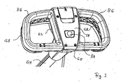
- Fig. 2
- eine Schrägansicht einer Handgriffanordnung.
-
Fig. 1 ist ein Schnittbild durch eine Handgriffanordnung in einer in der vertikalen Mittellängsebene eines handgeführten elektromotorisch angetriebenen Rasenmähers liegenden Schnittebene. Bei der skizzierten Handgriffanordnung ist für diese ein z. B. als zweischaliges Kunststoff-Spritzgussteil ausgeführtes Gehäuse GE vorgesehen, welches am oberen Ende eines zentralen Gestängeholms GH befestigt ist. Innerhalb des Gestängeholms ist geschützt ein Verbindungskabel KA zwischen einem Motorschalter MS im Gehäuse GE und dem Elektromotor im nicht mit dargestellten bodennahen Gerätegehäuse geführt. - Ein Griffbügel GB als ein erstes Betätigungselement ist um eine erste Schwenkachse S1 schwenkbar gelagert. Der Griffbügel GB schließt sich im wesentlichen U-förmig an das Gehäuse GE an und ragt mit einem Mittelteil GM in das Gehäuse hinein. Der Griffbügel ist in der Ausschaltstellung des Motors gezeichnet und zum Betrieb des Motors in Pfeilrichtung B1 zu bogenförmigen Abschnitten BG des Gehäuses GE hin in eine Betriebsstellung entgegen einer Federkraft verschwenkbar und durch eine zugleich einen bogenförmigen Abschnitt BG (
Fig. 2 ) des Gehäuses GE und den Griffbügel GB umfassende Hand des Benutzers in der Betriebsstellung haltbar. - In einer dem Benutzer nach schräg oben zuweisenden Stirnfläche SF des Gehäuses ist eine Aussparung SA vorgesehen, in welcher ein Bedienabschnitt BA eines zweiten Betätigungselements einliegt. Das zweite Betätigungselement ist durch eine im Gehäuse um eine zweite Schwenkachse S2 schwenkbar Hebelanordnung H2 mit dem der Schwenkachse entfernten Bedienabschnitt BA gebildet. Der Bedienabschnitt BA ist in der skizzierten Ruhestellung annähernd bündig mit der Stimfläche SF und kann vom Benutzer nach Art einer Taste entgegen der Rückstellkraft eines Federelements F2 in Betätigungsrichtung B2 um ein begrenztes Maß in das Gehäuse eingedrückt werden, wobei die gesamte Hebelanordnung H2 um die Schwenkachse S2 verschwenkt wird.
- Die Schalteranordnung MS ist als Ein-Taster ausgeführt und enthält ein Sperrelement SP, welches im skizzierten Ruhezustand eine Betätigung der Schaltertaste ST verhindert und entgegen einer Rückstellkraft in Entriegelungsrichtung BS verschoben werden kann. Das Sperrelement wird bei Betätigung der Hebelanordnung H2 über den Bedienabschnitt BA von der Hebelanordnung in Entriegelungsrichtung gedrückt und gibt in der Entriegelungsstellung die Taste ST des Schalters MS frei.
- Bei Betätigung des Griffbügels GB in Betätigungsrichtung B1 drückt das Mittelteil GM auf ein Zwischenfederelement F1, welches über eine um eine weitere Schwenkachse S3 schwenkbare Wippe SW auf die Schaltertaste einwirkt. Die Feder ist vorteilhaft im skizzierten Ruhezustand vorgespannt, wobei diese Vorspannung aber gering ist und insbesondere nicht ausreicht, die Schaltertaste ST über die Wippe ST entgegen dem Schaltwiderstand des Schalters einzudrücken. Bei Betätigung des Griffbügels GB wird die Feder F1 weiter gespannt und drückt die Wippe stärker auf die Schaltertaste ST.
- Ist der Schalter MS bei Betätigen des Griffbügels GB als erstem Betätigungselement durch das Sperrelement verriegelt, kann die Taste ST nicht eingedrückt werden und die Feder F1 wird bis zu einer maximalen Spannkraft in der Endstellung des Griffbügels gespannt. Wird danach bei in der Endstellung festgehaltenem Griffbügel GB und damit weiter bestehender Spannkraft über den Bedienabschnitt BA die Hebelanordnung H2 als zweites Betätigungselement bis in ihre Endstellung gedrückt, so wird über das dabei mit verschobene Sperrelement SP der Schalter MS entriegelt und die Spannkraft der Feder drückt über die Wippe SW die Taste ST in die Einschalt-Stellung des Schalters.
- Das erste Betätigungselement H2, BA kann danach wieder losgelassen werden. Der Schalter bleibt in der Einschalt-Stellung bis der Griffbügel wieder in die skizzierte Ruhestellung zurückkehrt und die eventuell gegebene geringe Vorspannung der Feder F1 nicht ausreicht, die Taste ST entgegen der Rückstellkraft des Schalters gedrückt zu halten. Nach Rückstellung der Taste ST in die Ausschalt-Stellung kann auch das Sperrelement SP in die Verriegelungsstellung zurückgleiten.
- Ist zum Zeitpunkt der Betätigung des Griffbügels GB die Hebelanordnung H2 bereits in ihrer Endstellung und das Sperrelement dadurch in Entriegelungsstellung, so wird während der Betätigungsbewegung B1 die Taste ST in die Einschalt-Stellung gedrückt, sobald die Feder F1 ausreichend gespannt ist, um den mechanischen Schaltwiderstand des Schalters zu überwinden.
- Innerhalb des zweiten Betätigungselements mit der Hebelanordnung HA und dem Bedienabschnitt BA ist die für die auf den Bedienabschnitt BA ausgeübte Kraft des Benutzers wirksame Hebellänge wenigstens doppelt so groß wie die für die Kraft zur Verschiebung des Sperrelements SP wirksame Hebellänge.
- Die schwenkbare Wippe ermöglicht vorteilhafterweise auch eine Einbaulage des Schalters MS mit von der Betätigungsrichtung B1 des Griffbügels stark abweichender Verschieberichtung der Schaltertaste ST.
- Geeignete Ein-Taster mit integriertem Sperrelement sind als fertige Bauteile kostengünstig erhältlich. Durch den Aufbau der Handgriffanordnung als zusammengesetzter Hohlkörper können solche handelsüblichen Schalter vorteilhaft eingebaut werden.
- Die vorstehend und die in den Ansprüchen angegebenen sowie die den Abbildungen entnehmbaren Merkmale sind sowohl einzeln als auch in verschiedener Kombination vorteilhaft realisierbar. Die Erfindung ist nicht auf die beschriebenen Ausführungsbeispiele beschränkt, sondern im Rahmen fachmännischen Könnens in mancherlei Weise abwandelbar.
Claims (10)
- Fahrbares Bodenbearbeitungsgerät mit einem motorischen, insbesondere elektromotorischen Antrieb und einer von einem bodennahen Gerätegehäuse über ein Gestänge beabstandeten Handgriffanordnung sowie mit einer Zweihand-Schutzschaltung mit einem ersten Betätigungselement an der Handgriffanordnung und einem zweiten Betätigungselement, wobei zum Start des Antriebs beide Betätigungselemente gleichzeitig in einer Betätigungs-Endstellung sein müssen, wobei das zweite Betätigungselement (H2, BA) in die Handgriffanordnung integriert ist und die Handgriffanordnung ein bezüglich des Gestänges (GH) feststehendes Gehäuse (GE) aufweist, in welchem ein Motorschalter (MS) und das zweite Betätigungselement (H2, BA) aufgenommen sind und an welchem das als Griffbügel (GB) ausgeführte erste Betätigungselement (GB, GM) schwenkbar gelagert ist, dadurch gekennzeichnet, dass das Gehäuse eine dem Benutzer zugewandte Mittenfläche (SF), in welcher ein Teil (BA) des zweiten Betätigungselements sichtbar und betätigbar ist, und seitlich der Mittenfläche dem Verlauf des Griffbügels (GB) folgende Bogenabschnitte (BG) aufweist.
- Gerät nach Anspruch 1, dadurch gekennzeichnet, dass der schwenkbare Griffbügel (GB) mehrere Griffpositionen aufweist.
- Gerät nach Anspruch 1 oder 2, dadurch gekennzeichnet, dass der Motorschalter (MS) als Ein-Taster ausgeführt ist.
- Gerät nach einem der Ansprüche 1 bis 3, dadurch gekennzeichnet, dass der Motorschalter ein Sperrelement (SP) enthält, welches durch das zweite Betätigungselement (H2,BA) entriegelbar ist.
- Gerät nach Anspruch 4, dadurch gekennzeichnet, dass das zweite Betätigungselement eine Schwenkhebelanordnung (H2) ist mit wenigstens zweifacher Kraftübersetzung zwischen der auf das zweite Betätigungselement (BA) ausgeübten Kraft und der auf das Sperrelement (SP) einwirkenden Kraft.
- Gerät nach Anspruch 4 oder 5, dadurch gekennzeichnet, dass dem zweiten Betätigungselement ein von dem Sperrelement unabhängiges Rückstell-Federelement (F2) zugeordnet ist.
- Gerät nach einem der Ansprüche 1 bis 6, dadurch gekennzeichnet, dass die zeitliche Abfolge der Betätigung der beiden Betätigungselemente für den Start des Antriebs unerheblich ist.
- Gerät nach einem der Ansprüche 1 bis 7, dadurch gekennzeichnet, dass bei Betätigen des ersten Betätigungselements vor dem zweiten Betätigungselement das Zwischenfederelement (F1) auf eine Spannkraft vorgespannt wird, welche nach Betätigung des zweiten Betätigungselements zur Auslösung des Motorschalters ausreicht.
- Gerät nach einem der Ansprüche 1 bis 8, dadurch gekennzeichnet, dass zwischen erstem Betätigungselement und Motorschalter eine schwenkbare Wippe (SW) aufweist, welche die Betätigungsrichtung des ersten Betätigungselements umsetzt in eine hiervon um wenigstens 60° verschiedene Schalterbetätigungsrichtung.
- Gerät nach einem der Ansprüche 1 bis 9, dadurch gekennzeichnet, dass das erste Betätigungselement (GB, GM) über ein Zwischenfederelement (F1) auf den Motorschalter (MS) einwirkt.
Applications Claiming Priority (1)
| Application Number | Priority Date | Filing Date | Title |
|---|---|---|---|
| DE102004034304A DE102004034304A1 (de) | 2004-07-15 | 2004-07-15 | Fahrbares Bodenbearbeitungsgerät |
Publications (2)
| Publication Number | Publication Date |
|---|---|
| EP1616472A1 EP1616472A1 (de) | 2006-01-18 |
| EP1616472B1 true EP1616472B1 (de) | 2009-05-20 |
Family
ID=35219485
Family Applications (1)
| Application Number | Title | Priority Date | Filing Date |
|---|---|---|---|
| EP05015189A Expired - Lifetime EP1616472B1 (de) | 2004-07-15 | 2005-07-13 | Fahrbares Bodenbearbeitungsgerät |
Country Status (3)
| Country | Link |
|---|---|
| EP (1) | EP1616472B1 (de) |
| AT (1) | ATE431701T1 (de) |
| DE (2) | DE102004034304A1 (de) |
Families Citing this family (2)
| Publication number | Priority date | Publication date | Assignee | Title |
|---|---|---|---|---|
| US7543430B2 (en) | 2007-09-10 | 2009-06-09 | Honda Motor Co., Ltd. | Button type blade brake clutch control |
| DE102017002353A1 (de) | 2017-03-11 | 2018-09-13 | Andreas Stihl Ag & Co. Kg | Handgeführtes Arbeitsgerät |
Family Cites Families (9)
| Publication number | Priority date | Publication date | Assignee | Title |
|---|---|---|---|---|
| DE7621569U1 (de) * | 1976-07-08 | 1977-08-11 | Stahlschmidt, Robert, 4800 Bielefeld | Rasenmaeher o.dgl. mit einer sicherheits-anlassvorrichtung |
| US4466308A (en) * | 1982-06-16 | 1984-08-21 | Conchemco, Incorporated | Control assembly for lawnmower having electrically started engine |
| DE8224741U1 (de) * | 1982-09-02 | 1983-03-17 | Robert Stahlschmidt RST Motorenwerk GmbH, 4800 Bielefeld | Sicherheitsvorrichtung für elektromotorisch angetriebene handgeführte Maschinen |
| GB8409220D0 (en) * | 1984-04-10 | 1984-05-23 | Black & Decker Inc | Garden tool |
| DE3500591A1 (de) * | 1985-01-10 | 1986-07-10 | Bär Elektrowerke GmbH & Co KG, 5885 Schalksmühle | Elektrische schaltvorrichtung |
| US5203147A (en) * | 1992-01-22 | 1993-04-20 | Ryobi Motor Products Corp. | Lawn mower activation switch |
| IT1292994B1 (it) * | 1997-05-23 | 1999-02-11 | Valex S R L Ora Valex S P A | Dispositivo di azionamento a doppio consenso particolarmente per tagliasiepi ed utensili similari. |
| DE10045598B4 (de) * | 2000-09-15 | 2014-03-20 | Andreas Stihl Ag & Co. | Führungsrohr für ein handgeführtes Arbeitsgerät |
| US7159377B2 (en) * | 2002-08-27 | 2007-01-09 | M Group, Inc. | Powered appliance and accessory |
-
2004
- 2004-07-15 DE DE102004034304A patent/DE102004034304A1/de not_active Withdrawn
-
2005
- 2005-07-13 EP EP05015189A patent/EP1616472B1/de not_active Expired - Lifetime
- 2005-07-13 AT AT05015189T patent/ATE431701T1/de active
- 2005-07-13 DE DE502005007304T patent/DE502005007304D1/de not_active Expired - Lifetime
Also Published As
| Publication number | Publication date |
|---|---|
| EP1616472A1 (de) | 2006-01-18 |
| ATE431701T1 (de) | 2009-06-15 |
| DE502005007304D1 (de) | 2009-07-02 |
| DE102004034304A1 (de) | 2006-02-09 |
Similar Documents
| Publication | Publication Date | Title |
|---|---|---|
| EP1944134B1 (de) | Tragbare, handgeführte Werkzeugmaschine | |
| EP1303383B1 (de) | Elektrokombihammer | |
| DE3040516A1 (de) | Sicherheitseinrichtung an einer motorsaege | |
| DE69931225T2 (de) | Sperrmechanismus für kraftbetriebenes Werkzeug | |
| DE202010008031U1 (de) | Verriegelungs-Schaltervorrichtung für ein Kraftwerkzeug | |
| DE3302544C2 (de) | ||
| EP1833642B1 (de) | Handwerkzeugmaschine mit einem stabhandgriff | |
| EP2656362B1 (de) | Arretierbarer elektrischer schalter | |
| DE102011087551B3 (de) | Verriegelungsmechanismus für einen Einschaltknopf eines Leistungsschalters | |
| DE3888888T2 (de) | Apparat für einen elektrisch betätigten Schalter. | |
| EP0047416B2 (de) | Sicherheitsschaltvorrichtung für einen Elektrorasenmäher | |
| DE202011108753U1 (de) | Handgeführtes Gerät mit einem Bedienungshebel | |
| DE102017002353A1 (de) | Handgeführtes Arbeitsgerät | |
| DE4421746C2 (de) | Motorisch angetriebene Heckenschere mit Zweihand-Sicherheitsbedienung | |
| DE2301471A1 (de) | Elektrischer schalter fuer tragbare elektrische geraete | |
| EP1616472A1 (de) | Fahrbares Bodenbearbeitungsgerät | |
| DE69900709T2 (de) | Sicherheitssperrvorrichtung für einen Hebelschalter | |
| DE4427759C2 (de) | Vorrichtung zur Zweihandbedienung | |
| DE2450577A1 (de) | Schalter fuer elektro-handwerkzeuge | |
| DE3324545A1 (de) | Elektromotorisch betriebenes handgeraet | |
| DE69616506T2 (de) | Angetriebenes Arbeitsgerät mit einer Betätigungsvorrichtung | |
| DE602004013191T2 (de) | Elektrowerkzeug mit doppelt steuerbarem schalter | |
| DE19839203C2 (de) | Sicherheitsvorrichtung für handgeführte Arbeitsgeräte mit motorischem Antrieb | |
| WO2002046556A2 (de) | Vorrichtung zur betätigung eines verschlusses an einer tür, klappe od. dgl., insbesondere bei einem fahrzeug | |
| DE202017103878U1 (de) | Motorbetriebenes Arbeitsgerät, insbesondere Heckenschere |
Legal Events
| Date | Code | Title | Description |
|---|---|---|---|
| PUAI | Public reference made under article 153(3) epc to a published international application that has entered the european phase |
Free format text: ORIGINAL CODE: 0009012 |
|
| AK | Designated contracting states |
Kind code of ref document: A1 Designated state(s): AT BE BG CH CY CZ DE DK EE ES FI FR GB GR HU IE IS IT LI LT LU LV MC NL PL PT RO SE SI SK TR |
|
| AX | Request for extension of the european patent |
Extension state: AL BA HR MK YU |
|
| 17P | Request for examination filed |
Effective date: 20060706 |
|
| 17Q | First examination report despatched |
Effective date: 20060809 |
|
| AKX | Designation fees paid |
Designated state(s): AT BE BG CH CY CZ DE DK EE ES FI FR GB GR HU IE IS IT LI LT LU LV MC NL PL PT RO SE SI SK TR |
|
| GRAP | Despatch of communication of intention to grant a patent |
Free format text: ORIGINAL CODE: EPIDOSNIGR1 |
|
| RIN1 | Information on inventor provided before grant (corrected) |
Inventor name: BESSERER, BERNHARD |
|
| GRAS | Grant fee paid |
Free format text: ORIGINAL CODE: EPIDOSNIGR3 |
|
| GRAA | (expected) grant |
Free format text: ORIGINAL CODE: 0009210 |
|
| AK | Designated contracting states |
Kind code of ref document: B1 Designated state(s): AT BE BG CH CY CZ DE DK EE ES FI FR GB GR HU IE IS IT LI LT LU LV MC NL PL PT RO SE SI SK TR |
|
| REG | Reference to a national code |
Ref country code: GB Ref legal event code: FG4D Free format text: NOT ENGLISH |
|
| REG | Reference to a national code |
Ref country code: CH Ref legal event code: EP |
|
| REG | Reference to a national code |
Ref country code: IE Ref legal event code: FG4D Free format text: LANGUAGE OF EP DOCUMENT: GERMAN |
|
| REF | Corresponds to: |
Ref document number: 502005007304 Country of ref document: DE Date of ref document: 20090702 Kind code of ref document: P |
|
| REG | Reference to a national code |
Ref country code: SE Ref legal event code: TRGR |
|
| PG25 | Lapsed in a contracting state [announced via postgrant information from national office to epo] |
Ref country code: ES Free format text: LAPSE BECAUSE OF FAILURE TO SUBMIT A TRANSLATION OF THE DESCRIPTION OR TO PAY THE FEE WITHIN THE PRESCRIBED TIME-LIMIT Effective date: 20090831 Ref country code: LT Free format text: LAPSE BECAUSE OF FAILURE TO SUBMIT A TRANSLATION OF THE DESCRIPTION OR TO PAY THE FEE WITHIN THE PRESCRIBED TIME-LIMIT Effective date: 20090520 Ref country code: FI Free format text: LAPSE BECAUSE OF FAILURE TO SUBMIT A TRANSLATION OF THE DESCRIPTION OR TO PAY THE FEE WITHIN THE PRESCRIBED TIME-LIMIT Effective date: 20090520 Ref country code: PT Free format text: LAPSE BECAUSE OF FAILURE TO SUBMIT A TRANSLATION OF THE DESCRIPTION OR TO PAY THE FEE WITHIN THE PRESCRIBED TIME-LIMIT Effective date: 20090920 |
|
| NLV1 | Nl: lapsed or annulled due to failure to fulfill the requirements of art. 29p and 29m of the patents act | ||
| PG25 | Lapsed in a contracting state [announced via postgrant information from national office to epo] |
Ref country code: LV Free format text: LAPSE BECAUSE OF FAILURE TO SUBMIT A TRANSLATION OF THE DESCRIPTION OR TO PAY THE FEE WITHIN THE PRESCRIBED TIME-LIMIT Effective date: 20090520 Ref country code: NL Free format text: LAPSE BECAUSE OF FAILURE TO SUBMIT A TRANSLATION OF THE DESCRIPTION OR TO PAY THE FEE WITHIN THE PRESCRIBED TIME-LIMIT Effective date: 20090520 Ref country code: SI Free format text: LAPSE BECAUSE OF FAILURE TO SUBMIT A TRANSLATION OF THE DESCRIPTION OR TO PAY THE FEE WITHIN THE PRESCRIBED TIME-LIMIT Effective date: 20090520 Ref country code: IS Free format text: LAPSE BECAUSE OF FAILURE TO SUBMIT A TRANSLATION OF THE DESCRIPTION OR TO PAY THE FEE WITHIN THE PRESCRIBED TIME-LIMIT Effective date: 20090920 Ref country code: PL Free format text: LAPSE BECAUSE OF FAILURE TO SUBMIT A TRANSLATION OF THE DESCRIPTION OR TO PAY THE FEE WITHIN THE PRESCRIBED TIME-LIMIT Effective date: 20090520 |
|
| REG | Reference to a national code |
Ref country code: IE Ref legal event code: FD4D |
|
| PG25 | Lapsed in a contracting state [announced via postgrant information from national office to epo] |
Ref country code: IE Free format text: LAPSE BECAUSE OF FAILURE TO SUBMIT A TRANSLATION OF THE DESCRIPTION OR TO PAY THE FEE WITHIN THE PRESCRIBED TIME-LIMIT Effective date: 20090520 Ref country code: EE Free format text: LAPSE BECAUSE OF FAILURE TO SUBMIT A TRANSLATION OF THE DESCRIPTION OR TO PAY THE FEE WITHIN THE PRESCRIBED TIME-LIMIT Effective date: 20090520 Ref country code: DK Free format text: LAPSE BECAUSE OF FAILURE TO SUBMIT A TRANSLATION OF THE DESCRIPTION OR TO PAY THE FEE WITHIN THE PRESCRIBED TIME-LIMIT Effective date: 20090520 Ref country code: CZ Free format text: LAPSE BECAUSE OF FAILURE TO SUBMIT A TRANSLATION OF THE DESCRIPTION OR TO PAY THE FEE WITHIN THE PRESCRIBED TIME-LIMIT Effective date: 20090520 Ref country code: RO Free format text: LAPSE BECAUSE OF FAILURE TO SUBMIT A TRANSLATION OF THE DESCRIPTION OR TO PAY THE FEE WITHIN THE PRESCRIBED TIME-LIMIT Effective date: 20090520 |
|
| BERE | Be: lapsed |
Owner name: GARDENA MANUFACTURING G.M.B.H. Effective date: 20090731 |
|
| PG25 | Lapsed in a contracting state [announced via postgrant information from national office to epo] |
Ref country code: SK Free format text: LAPSE BECAUSE OF FAILURE TO SUBMIT A TRANSLATION OF THE DESCRIPTION OR TO PAY THE FEE WITHIN THE PRESCRIBED TIME-LIMIT Effective date: 20090520 Ref country code: MC Free format text: LAPSE BECAUSE OF NON-PAYMENT OF DUE FEES Effective date: 20090731 |
|
| REG | Reference to a national code |
Ref country code: CH Ref legal event code: PL |
|
| PLBE | No opposition filed within time limit |
Free format text: ORIGINAL CODE: 0009261 |
|
| STAA | Information on the status of an ep patent application or granted ep patent |
Free format text: STATUS: NO OPPOSITION FILED WITHIN TIME LIMIT |
|
| PG25 | Lapsed in a contracting state [announced via postgrant information from national office to epo] |
Ref country code: BG Free format text: LAPSE BECAUSE OF FAILURE TO SUBMIT A TRANSLATION OF THE DESCRIPTION OR TO PAY THE FEE WITHIN THE PRESCRIBED TIME-LIMIT Effective date: 20090820 |
|
| 26N | No opposition filed |
Effective date: 20100223 |
|
| PG25 | Lapsed in a contracting state [announced via postgrant information from national office to epo] |
Ref country code: CH Free format text: LAPSE BECAUSE OF NON-PAYMENT OF DUE FEES Effective date: 20090731 Ref country code: LI Free format text: LAPSE BECAUSE OF NON-PAYMENT OF DUE FEES Effective date: 20090731 |
|
| PG25 | Lapsed in a contracting state [announced via postgrant information from national office to epo] |
Ref country code: BE Free format text: LAPSE BECAUSE OF NON-PAYMENT OF DUE FEES Effective date: 20090731 |
|
| PG25 | Lapsed in a contracting state [announced via postgrant information from national office to epo] |
Ref country code: GR Free format text: LAPSE BECAUSE OF FAILURE TO SUBMIT A TRANSLATION OF THE DESCRIPTION OR TO PAY THE FEE WITHIN THE PRESCRIBED TIME-LIMIT Effective date: 20090821 |
|
| PG25 | Lapsed in a contracting state [announced via postgrant information from national office to epo] |
Ref country code: IT Free format text: LAPSE BECAUSE OF FAILURE TO SUBMIT A TRANSLATION OF THE DESCRIPTION OR TO PAY THE FEE WITHIN THE PRESCRIBED TIME-LIMIT Effective date: 20090520 |
|
| PG25 | Lapsed in a contracting state [announced via postgrant information from national office to epo] |
Ref country code: LU Free format text: LAPSE BECAUSE OF NON-PAYMENT OF DUE FEES Effective date: 20090713 |
|
| PG25 | Lapsed in a contracting state [announced via postgrant information from national office to epo] |
Ref country code: HU Free format text: LAPSE BECAUSE OF FAILURE TO SUBMIT A TRANSLATION OF THE DESCRIPTION OR TO PAY THE FEE WITHIN THE PRESCRIBED TIME-LIMIT Effective date: 20091121 |
|
| PG25 | Lapsed in a contracting state [announced via postgrant information from national office to epo] |
Ref country code: TR Free format text: LAPSE BECAUSE OF FAILURE TO SUBMIT A TRANSLATION OF THE DESCRIPTION OR TO PAY THE FEE WITHIN THE PRESCRIBED TIME-LIMIT Effective date: 20090520 |
|
| PG25 | Lapsed in a contracting state [announced via postgrant information from national office to epo] |
Ref country code: CY Free format text: LAPSE BECAUSE OF FAILURE TO SUBMIT A TRANSLATION OF THE DESCRIPTION OR TO PAY THE FEE WITHIN THE PRESCRIBED TIME-LIMIT Effective date: 20090520 |
|
| PGFP | Annual fee paid to national office [announced via postgrant information from national office to epo] |
Ref country code: SE Payment date: 20120514 Year of fee payment: 8 Ref country code: FR Payment date: 20120525 Year of fee payment: 8 |
|
| PGFP | Annual fee paid to national office [announced via postgrant information from national office to epo] |
Ref country code: AT Payment date: 20120508 Year of fee payment: 8 |
|
| PGFP | Annual fee paid to national office [announced via postgrant information from national office to epo] |
Ref country code: DE Payment date: 20130520 Year of fee payment: 9 |
|
| PGFP | Annual fee paid to national office [announced via postgrant information from national office to epo] |
Ref country code: GB Payment date: 20130823 Year of fee payment: 9 |
|
| REG | Reference to a national code |
Ref country code: SE Ref legal event code: EUG |
|
| REG | Reference to a national code |
Ref country code: AT Ref legal event code: MM01 Ref document number: 431701 Country of ref document: AT Kind code of ref document: T Effective date: 20130713 |
|
| REG | Reference to a national code |
Ref country code: FR Ref legal event code: ST Effective date: 20140331 |
|
| PG25 | Lapsed in a contracting state [announced via postgrant information from national office to epo] |
Ref country code: SE Free format text: LAPSE BECAUSE OF NON-PAYMENT OF DUE FEES Effective date: 20130714 |
|
| PG25 | Lapsed in a contracting state [announced via postgrant information from national office to epo] |
Ref country code: AT Free format text: LAPSE BECAUSE OF NON-PAYMENT OF DUE FEES Effective date: 20130713 Ref country code: FR Free format text: LAPSE BECAUSE OF NON-PAYMENT OF DUE FEES Effective date: 20130731 |
|
| REG | Reference to a national code |
Ref country code: DE Ref legal event code: R119 Ref document number: 502005007304 Country of ref document: DE |
|
| GBPC | Gb: european patent ceased through non-payment of renewal fee |
Effective date: 20140713 |
|
| PG25 | Lapsed in a contracting state [announced via postgrant information from national office to epo] |
Ref country code: DE Free format text: LAPSE BECAUSE OF NON-PAYMENT OF DUE FEES Effective date: 20150203 |
|
| REG | Reference to a national code |
Ref country code: DE Ref legal event code: R119 Ref document number: 502005007304 Country of ref document: DE Effective date: 20150203 |
|
| PG25 | Lapsed in a contracting state [announced via postgrant information from national office to epo] |
Ref country code: GB Free format text: LAPSE BECAUSE OF NON-PAYMENT OF DUE FEES Effective date: 20140713 |