EP1616124B2 - Louvered luminaire - Google Patents
Louvered luminaire Download PDFInfo
- Publication number
- EP1616124B2 EP1616124B2 EP04728803.0A EP04728803A EP1616124B2 EP 1616124 B2 EP1616124 B2 EP 1616124B2 EP 04728803 A EP04728803 A EP 04728803A EP 1616124 B2 EP1616124 B2 EP 1616124B2
- Authority
- EP
- European Patent Office
- Prior art keywords
- grid
- luminaire according
- luminaire
- lamp
- reflectors
- Prior art date
- Legal status (The legal status is an assumption and is not a legal conclusion. Google has not performed a legal analysis and makes no representation as to the accuracy of the status listed.)
- Expired - Lifetime
Links
- 238000003466 welding Methods 0.000 claims 1
- 230000000694 effects Effects 0.000 description 12
- 238000005286 illumination Methods 0.000 description 6
- 238000001746 injection moulding Methods 0.000 description 5
- 238000004519 manufacturing process Methods 0.000 description 5
- 229910052736 halogen Inorganic materials 0.000 description 4
- 150000002367 halogens Chemical class 0.000 description 4
- 238000012216 screening Methods 0.000 description 4
- 238000000576 coating method Methods 0.000 description 3
- 239000000243 solution Substances 0.000 description 3
- 229910052782 aluminium Inorganic materials 0.000 description 2
- XAGFODPZIPBFFR-UHFFFAOYSA-N aluminium Chemical compound [Al] XAGFODPZIPBFFR-UHFFFAOYSA-N 0.000 description 2
- 238000005282 brightening Methods 0.000 description 2
- 239000011248 coating agent Substances 0.000 description 2
- 238000000034 method Methods 0.000 description 2
- 230000003287 optical effect Effects 0.000 description 2
- 238000003860 storage Methods 0.000 description 2
- 238000007740 vapor deposition Methods 0.000 description 2
- 230000000007 visual effect Effects 0.000 description 2
- 229910000831 Steel Inorganic materials 0.000 description 1
- 238000010276 construction Methods 0.000 description 1
- 238000005265 energy consumption Methods 0.000 description 1
- 230000004313 glare Effects 0.000 description 1
- 230000001771 impaired effect Effects 0.000 description 1
- 238000009434 installation Methods 0.000 description 1
- 238000005304 joining Methods 0.000 description 1
- 229910052751 metal Inorganic materials 0.000 description 1
- 239000002184 metal Substances 0.000 description 1
- 239000000843 powder Substances 0.000 description 1
- 230000005855 radiation Effects 0.000 description 1
- 238000002310 reflectometry Methods 0.000 description 1
- 239000010959 steel Substances 0.000 description 1
Images


Classifications
-
- F—MECHANICAL ENGINEERING; LIGHTING; HEATING; WEAPONS; BLASTING
- F21—LIGHTING
- F21V—FUNCTIONAL FEATURES OR DETAILS OF LIGHTING DEVICES OR SYSTEMS THEREOF; STRUCTURAL COMBINATIONS OF LIGHTING DEVICES WITH OTHER ARTICLES, NOT OTHERWISE PROVIDED FOR
- F21V11/00—Screens not covered by groups F21V1/00, F21V3/00, F21V7/00 or F21V9/00
- F21V11/06—Screens not covered by groups F21V1/00, F21V3/00, F21V7/00 or F21V9/00 using crossed laminae or strips, e.g. grid-shaped louvers; using lattices or honeycombs
-
- F—MECHANICAL ENGINEERING; LIGHTING; HEATING; WEAPONS; BLASTING
- F21—LIGHTING
- F21V—FUNCTIONAL FEATURES OR DETAILS OF LIGHTING DEVICES OR SYSTEMS THEREOF; STRUCTURAL COMBINATIONS OF LIGHTING DEVICES WITH OTHER ARTICLES, NOT OTHERWISE PROVIDED FOR
- F21V11/00—Screens not covered by groups F21V1/00, F21V3/00, F21V7/00 or F21V9/00
-
- F—MECHANICAL ENGINEERING; LIGHTING; HEATING; WEAPONS; BLASTING
- F21—LIGHTING
- F21V—FUNCTIONAL FEATURES OR DETAILS OF LIGHTING DEVICES OR SYSTEMS THEREOF; STRUCTURAL COMBINATIONS OF LIGHTING DEVICES WITH OTHER ARTICLES, NOT OTHERWISE PROVIDED FOR
- F21V17/00—Fastening of component parts of lighting devices, e.g. shades, globes, refractors, reflectors, filters, screens, grids or protective cages
- F21V17/10—Fastening of component parts of lighting devices, e.g. shades, globes, refractors, reflectors, filters, screens, grids or protective cages characterised by specific fastening means or way of fastening
- F21V17/16—Fastening of component parts of lighting devices, e.g. shades, globes, refractors, reflectors, filters, screens, grids or protective cages characterised by specific fastening means or way of fastening by deformation of parts; Snap action mounting
- F21V17/164—Fastening of component parts of lighting devices, e.g. shades, globes, refractors, reflectors, filters, screens, grids or protective cages characterised by specific fastening means or way of fastening by deformation of parts; Snap action mounting the parts being subjected to bending, e.g. snap joints
-
- F—MECHANICAL ENGINEERING; LIGHTING; HEATING; WEAPONS; BLASTING
- F21—LIGHTING
- F21V—FUNCTIONAL FEATURES OR DETAILS OF LIGHTING DEVICES OR SYSTEMS THEREOF; STRUCTURAL COMBINATIONS OF LIGHTING DEVICES WITH OTHER ARTICLES, NOT OTHERWISE PROVIDED FOR
- F21V7/00—Reflectors for light sources
- F21V7/0008—Reflectors for light sources providing for indirect lighting
- F21V7/0016—Reflectors for light sources providing for indirect lighting on lighting devices that also provide for direct lighting, e.g. by means of independent light sources, by splitting of the light beam, by switching between both lighting modes
-
- F—MECHANICAL ENGINEERING; LIGHTING; HEATING; WEAPONS; BLASTING
- F21—LIGHTING
- F21V—FUNCTIONAL FEATURES OR DETAILS OF LIGHTING DEVICES OR SYSTEMS THEREOF; STRUCTURAL COMBINATIONS OF LIGHTING DEVICES WITH OTHER ARTICLES, NOT OTHERWISE PROVIDED FOR
- F21V7/00—Reflectors for light sources
- F21V7/005—Reflectors for light sources with an elongated shape to cooperate with linear light sources
-
- F—MECHANICAL ENGINEERING; LIGHTING; HEATING; WEAPONS; BLASTING
- F21—LIGHTING
- F21S—NON-PORTABLE LIGHTING DEVICES; SYSTEMS THEREOF; VEHICLE LIGHTING DEVICES SPECIALLY ADAPTED FOR VEHICLE EXTERIORS
- F21S8/00—Lighting devices intended for fixed installation
- F21S8/04—Lighting devices intended for fixed installation intended only for mounting on a ceiling or the like overhead structures
- F21S8/06—Lighting devices intended for fixed installation intended only for mounting on a ceiling or the like overhead structures by suspension
-
- F—MECHANICAL ENGINEERING; LIGHTING; HEATING; WEAPONS; BLASTING
- F21—LIGHTING
- F21V—FUNCTIONAL FEATURES OR DETAILS OF LIGHTING DEVICES OR SYSTEMS THEREOF; STRUCTURAL COMBINATIONS OF LIGHTING DEVICES WITH OTHER ARTICLES, NOT OTHERWISE PROVIDED FOR
- F21V23/00—Arrangement of electric circuit elements in or on lighting devices
- F21V23/02—Arrangement of electric circuit elements in or on lighting devices the elements being transformers, impedances or power supply units, e.g. a transformer with a rectifier
- F21V23/026—Fastening of transformers or ballasts
-
- F—MECHANICAL ENGINEERING; LIGHTING; HEATING; WEAPONS; BLASTING
- F21—LIGHTING
- F21W—INDEXING SCHEME ASSOCIATED WITH SUBCLASSES F21K, F21L, F21S and F21V, RELATING TO USES OR APPLICATIONS OF LIGHTING DEVICES OR SYSTEMS
- F21W2131/00—Use or application of lighting devices or systems not provided for in codes F21W2102/00-F21W2121/00
- F21W2131/40—Lighting for industrial, commercial, recreational or military use
- F21W2131/402—Lighting for industrial, commercial, recreational or military use for working places
-
- F—MECHANICAL ENGINEERING; LIGHTING; HEATING; WEAPONS; BLASTING
- F21—LIGHTING
- F21Y—INDEXING SCHEME ASSOCIATED WITH SUBCLASSES F21K, F21L, F21S and F21V, RELATING TO THE FORM OR THE KIND OF THE LIGHT SOURCES OR OF THE COLOUR OF THE LIGHT EMITTED
- F21Y2103/00—Elongate light sources, e.g. fluorescent tubes
Definitions
- the present invention relates to a luminaire with a grid, which has openings provided for the emission of light.
- rod-shaped light sources such as fluorescent tubes.
- the use of fluorescent lamps ensures a high light output with a relatively low energy consumption.
- such a grid lamp consists of an elongated lamp housing, which has lamp holders for holding and electrical connection of at least one elongate lamp in its end regions.
- the housing which also usually also an operating device for the lamp - for example, an electronic ballast - receives, has in its lower part further holding elements, with the aid of a luminous grid seen in the emission can be arranged and fixed in front of the lamp.
- the grid is usually a one-piece element, which is snapped onto the underside of the lamp housing or on the fastening or holding means provided there.
- Gas discharge lamps in particular the fluorescent lamps mainly used for normal room lighting are available in different lengths.
- luminaires of the same type in each of which a lamp of different lengths can be used, it is necessary to provide luminaire housing and luminaire grid in the corresponding lengths, the production of these elements in different lengths, however, associated with an increased cost is.
- the grid is formed by a plurality of individual modules, which are assembled into an elongated luminaire grid. Due to the number of modules used, the length of the entire grid can also be influenced in a simple manner.
- the present invention is therefore based on the object of specifying a cost-effective alternative to the production of luminaires of the type described above. At the same time, however, the luminaires should look appealing and have a very high-quality effect.
- the luminaire according to the invention has means for holding and for electrically connecting a tubular lamp and a plurality of grid modules arranged in front of the lamp, viewed in the emission direction, which have respective passage openings provided for the emission of light.
- the grid modules are arranged one behind the other to form an elongated luminaire grid and held together by holding elements, wherein according to the invention the holding elements are formed by profile elements which can be snapped onto the grid modules in the form of connecting profiles.
- the solution according to the invention provides for a luminaire grid to be formed from a plurality of individual grid modules which, taken on their own, are relatively short and are arranged or assembled together to form the grid of suitable length.
- This makes it possible to provide only a single raster module of a given length available, which is assembled with several similar modules to light grids in the desired lengths.
- grid modules with a length of 300 mm can be provided, which are assembled to the usual lengths of 600, 1200 and 1500 mm.
- the costs can thereby be considerably reduced because only a single tool is required for the raster modules, which are preferably produced by plastic injection molding. The considerable cost of tools in further lengths can be saved by the present invention.
- the holding together of the various grid modules to a single luminaire grid is carried out according to the invention by means of laterally alsschnappbarer profile elements.
- profile elements can be very slim and are stabilized in conjunction with the grid modules, so that the overall result is a very stable arrangement.
- the profile elements can even replace the usually required luminaire housing, whereby further costs can be saved.
- the assembly of a plurality of modules into a single luminaire grid via the lateral snap-fastening of the profile elements can take place much more easily and quickly.
- the luminaire can also be used for indirect lighting, ie a part of the light emitted by the lamp is emitted against the main light emission direction to the top, for example, to lighten the ceiling.
- the use of only laterally aufschnappbaren profile elements even particularly advantageous because in contrast to a conventional luminaire housing, which is usually designed in section U-shaped, no partial holes must be stamped or milled into the housing bottom, which the allow indirect light emission.
- the supply and removal of electrical lines is simplified by the use of only laterally disposed profile elements.
- the individual grid modules assembled to form the luminaire grid preferably consist - as already mentioned - of plastic. This has the consequence that the individual modules can expand and contract slightly as a result of the temperature differences that occur. This could create a narrow gap between the grid modules, can escape through the light, which affects the visual appearance of the lamp.
- the grid modules according to the invention are compressed by provided at the longitudinal ends of the luminaire grid frontal springs, by elastic bands or the like in the longitudinal direction. This ensures that the individual raster modules still abut each other even after temperature fluctuations and no unwanted light emission takes place.
- the holding together of the raster modules by the lateral profile elements according to the invention is preferably carried out with the aid of guide grooves and / or snap lugs, which allow a locking of the individual elements together.
- the profile elements can have a greater height than the grid modules themselves, which above the luminaire grid is formed by a space enclosed by the profile elements or laterally covered space, which can be used for example for receiving lamp operating devices.
- Another possibility is to form the lateral profile elements in cross-section U-shaped, which in addition to the luminaire grid a space is created in the corresponding lamp operating devices can be arranged.
- the luminaire has two laterally juxtaposed light grids of the type described above, which are connected to one another via a connecting profile arranged therebetween. Overall, therefore, the possibility is created to produce a grid lamp in a very simple and inexpensive manner.
- Another advantageous development of the present invention relates to the design of the individual raster modules.
- these each have a longitudinally extending back reflector, which is intended to reflect a part of the light emitted by the lamp against the emission direction.
- passage openings are arranged in the back reflector, which are intended to pass a part of the light emitted by the lamp in the emission direction.
- pot reflectors can be connected to these openings.
- the basic idea of this particular embodiment of the individual grid modules is to emit the light of a single tubular lamp via a plurality of light exit openings, followed by cup-shaped reflectors.
- the impression of a series arrangement of individual halogen beams is achieved, whereby the lights are given a particularly high-quality appearance.
- a variety of appealing lighting effects can be achieved.
- a corresponding grid module is characterized by its simple structure, since the arrangement consisting of the back reflector and the pot reflectors can be formed in one piece, which - as already mentioned above - is achieved in that the grid modules are produced by injection molding.
- the pot reflectors are connected to each other at their edge regions via a connecting plate arranged parallel to the lamp, wherein the connecting plate may also be integrally connected to the reflectors or the entire Räserermodul.
- the connecting plate itself is designed to be transparent. Namely, when a part of the light emitted from the tubular lamp is directed into an area outside the pot reflectors, the structure thereof can be recognized by the transparent connecting plate.
- the introduction of the light into the area outside the pot reflectors can be achieved, for example, by virtue of the fact that the back reflector is at least partially translucent. It is also possible to color the back reflector in its transparent areas, so that the connection plate appears in a changed color.
- the pot reflectors can protrude with their light exit openings on the connection plate or ends flush with this.
- the rear reflector is preferably designed such that it at least partially surrounds the lamp. In particular, it can be semicircular, as seen in cross-section.
- Another advantage of the specially designed raster modules is also that part of the light emitted by the lamp is used for indirect illumination.
- it could be provided to provide on the side opposite the pot reflectors side of the lamp, a Abblend- or filter plate over which a part of the output from the lamp Light is directed to the ceiling of the room to be illuminated.
- the edge regions of this screening or filter plate can be designed to be reflective in order to allow the deflection of part of the light into the space surrounding the pot reflectors. Again, it is possible to make the translucent area of the screening or filter plate colored and thus to make the ceiling area appear above the lamp in a different color.
- FIGS. 1 to 12 initially show basic options for designing a grid lamp. Furthermore, a particularly preferred embodiment of a raster module is described.
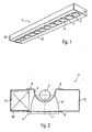
- Lamp 1 shown in section consists essentially of a tubular elongated lamp 2, which is preferably a fluorescent lamp, as well as one of three grid modules 3 connected in series and arranged in the emission direction laterally or in front of the lamp 2 luminaire grid.
- the luminaire grid or the raster modules 3 are each formed by a semi-circular semi-reflector 4 extending in the longitudinal direction of the lamp 2, from which several pot reflectors 6 with a circular light exit opening 7 extend in the emission direction.
- the lamp 2 is arranged inside the semicircular longitudinal reflector 4.
- the pot reflectors 6 adjoin passage openings of the back reflector 4, so that part of the light radiated by the lamp 2 is directed downward via these passage openings and the pot reflectors 6.
- the pot reflectors 6 thus serve for direct illumination of the area below the lamp 1 and have a shape by which the light emitted by the lamp 2 down to a predetermined exit angle is limited. Since dazzling effects are avoided in this way, the luminaire 1 according to the invention can be used in particular for room lighting in office workplaces.
- This operating device 11 may in particular be an electronic Ballast for operating a gas discharge lamp, in particular a fluorescent tube act on the representation of the versions for holding and electrical connection of the lamp 2 has been omitted for reasons of clarity.
- the side boxes 10 serve the side boxes 10 as holding elements also to hold the successively arranged grid modules 3 to the luminaire grid.
- the attachment of the two side boxes 10 to the grid modules 3 takes place in the illustrated example with the aid of side bars 9, which protrude from the outer sides of the rear reflector 4, and a parallel to these side bars 9 arranged connecting plate 8.
- This connecting plate 8 connects the pot reflectors 6 at their edge regions , wherein the pot reflectors 6 project slightly with their light exit openings 7 with respect to the connecting plate 8.
- the connecting plate 8 and the side bars 9 also serve to generate special lighting effects, as will also be explained later.
- part of the light emitted by the lamp 2 is also directed upwards via the back reflector 4 and accordingly serves for indirect room lighting.
- the lighting properties of the lamp 1 can be adapted to external conditions.
- a raster module 3 with the back reflector 4 and the pot reflectors 6 is preferably formed by a single part, which is produced for example by injection molding.
- the raster module 3 can be produced in the ideal case with a simply designed, slide-less mold, with more complex structures, the workpiece is removed by means of a sliding technique.
- the connecting plate 8 is part of this one-piece plastic part, which in an enlarged view in the FIGS. 3 and 4 is shown.
- the underside of the back reflector 4 has a plurality of openings 5, to which the pot reflectors connect 6, which in turn are connected in their end regions on the approximately 1 - 2 mm thick connecting plate 8.
- the pot reflectors 6, which are provided with a reflection layer at least on their insides, preferably have a size corresponding to the usual halogen lamps of approximately 40 to 60 mm in diameter.
- the inside of the pot reflectors 6 can be provided to make the inside of the pot reflectors 6 faceted.
- the production of the individual facets takes place already during the production of the plastic part during the injection molding and is achieved by an appropriate design of the molds.
- the application of the reflection layer is preferably carried out by vapor deposition of an aluminum coating in a high vacuum.
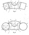
- Particular lighting effects can be generated in the luminaire 1 with the preferred raster modules 3, characterized in that the different areas of the raster modules 3 are formed differently reflective or translucent. This will be explained below with reference to FIGS. 5 and 6 that have two variants of in FIG. 1 illustrated lamp 1 show are explained.
- FIG. 1 Opposite the in FIG. 1
- the light shown differs in FIG. 5 illustrated variant by the inclined arrangement of the two side boxes 10 through which the lamp 1 is given a whole changed shape.
- the outer sides of the pot reflectors 6 are illuminated, so that through the transparent connecting plate 8 through the pot shape is recognizable.
- This brightening of the outer sides of the pot reflectors 6 is achieved in that the back reflector 4 is at least in its upper regions teillicht devisage so that a portion of the light emitted by the lamp 2 light can pass through the back reflector 4.
- This light thus falls in a light chamber, which is bounded by the side wall of the rear reflector 4, the pot reflectors 6, the connecting plate 8 and additional reflectors 12 on both sides of the pot reflectors 6.
- the light entering the light chamber can leave it via the connecting plate 8 again, so that the outside of the pot reflectors 6 can be seen.
- Another advantage of this embodiment is that the lamp 1 does not appear dark when viewed at a low angle range, but rather represents a luminous but glare-free body.
- FIG. 6 illustrated variant in which circular side boxes 10 are provided in the section reached.
- an over the length of the lamp 2 extending, curved in section Abblend- or filter plate 13 is provided at the top of the lamp 1, which is translucent in its central region 14 so that a portion of the light emitted by the lamp 2 upwards can be radiated and used for ceiling lighting.
- the screening or filter plate 13 is designed to be diffusely reflecting, for example coated in white, so that the light incident on these regions 15 by the lamp 2 is reflected downwards.
- the two side bars 9 are transparent, so that the light reflected at the side portions 15 of the screening or filter plate 13 light on these side bars 9 in the area between the side boxes 10 and the pot reflectors 6, the outside of the pot reflectors. 6 illuminate and on the transparent Connection plate 8 can leave again.
- the back reflector 4 may also be formed completely reflecting.
- a further education of in FIG. 6 illustrated variant may be to form the side bars 9 as a color filter, so that the outside of the pot reflectors 6 illuminating light is colored. As a result, additional color effects can be achieved, but do not affect the light emitted via the pot reflectors 6 down and used for the actual room lighting.
- the design as a color filter can of course also in the in FIG. 5 be provided variant shown.
- Abblend- or filter plate 13 may be used in the other variants of the lamp 1 according to the invention and, for example, also be designed as a color filter to make the ceiling area surrounding the lamp appear in a different color.
- color filters, reflective surfaces or partial covers can be combined in any way to achieve different lighting effects.
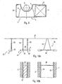
- the lamp according to the invention can also be provided for mounting on a mounting rail 16, as in the in FIG. 7 variant shown is the case.
- the U-shaped mounting rail 16 also serves to accommodate the operating device 11 for the lamp 2.
- the attachment of the lamp 1 to the mounting rail 16 is effected by means of a cap 17, which is inserted from the bottom into the mounting rail 16 and mechanically connected thereto - For example, locked - can be.
- On the underside of the mounting box 17 is also a roof reflector 18, which is arranged above the lamp 2 in the mounted state of the lamp 1. This roof reflector 18 is designed in such a way that the light radiated laterally upwards by the lamp 2 brightens the ceiling area surrounding the mounting rail 16.
- the attachment of the luminaire grid to the mounting rail 16 and the end cap 17 is carried out with the help of end portions 19, which hold the various components of the lamp 1, in particular the assembled to the luminaire grid raster modules 3.
- FIG. 8 shows a two-lamp variant of a grid lamp 1, in which two fluorescent lamps 2 and the lamp associated lamp grid are arranged on both sides of a box 20a.
- the ballasts 11 for operating the lamps 2 are both arranged in the box 20a, on the sides facing away from the box 20a, the grid modules 3 of C-shaped side walls 20 are closed and held together.
- FIG. 9 shows an asymmetrical variant of a grid lamp 1, in which a further side box 10, which in the embodiments of the FIGS. 1 . 5 and 6 was provided for reasons of symmetry was waived. Instead, in turn, a C-shaped side wall closes the luminaire grid on the opposite side of the box 10.
- FIG. 9 The luminaire shown in its asymmetric form can be fastened alone to a ceiling 21 of a room by means of a fastening rod 23 or ropes, as shown in FIG FIG. 10a is shown on the left side.
- a fastening rod 23 or ropes as shown in FIG. 10a is shown on the left side.
- the two asymmetrical lights are connected to each other via connecting pipes 28, wherein the overall arrangement by means of steel cables 27 is attached to the ceiling 21.
- FIG. 10b shows the undersides of these two variants.
- pot lights can basically be chosen arbitrarily.
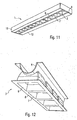
- the grid modules 3 in an enlarged view in FIG. 12 are shown, pot reflectors 6 are provided with a square light exit opening 7. Further, in this embodiment, apart from the fact that the edge portions of the pot light 6 protrude beyond the connecting plate 8.
- pot reflectors 6 may also be oval or rectangular.
- the reflectivity of the individual regions of a raster module 3 can be designed individually.
- the pot reflectors 6 can be made very smooth on the inside, so that when vapor deposition creates a high gloss, while the surrounding the pot reflectors 6 connecting plate 8 can be structured somewhat coarser, so that there is a matte layer. This can already be taken into account when designing the injection molding tool, so that no reworking of the plastic workpiece is necessary.
- the assembled from the special grid modules luminaire grid is thus characterized by the variety of lighting effects to be achieved with it, but have no effect on the functionality of the lamp in the room lighting or lighting of workplaces. In other words, despite the various optical effects, the luminaire is still able to illuminate offices appropriately.
- a luminaire grid in the sense of the present invention can be formed by any type of grid modules with light exit openings for light emission.
- the raster module - as in the preferred variant of Fig. 3, 4 and 11 - also allows an indirect light emission.
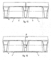
- the grid modules 3 are injected in a single length of 300 mm in plastic. These individual grid modules 3 can then be combined to form lamp grids in the usual lengths of 600 1200 and 1500 mm. As shown in the FIGS. 13 and 14 This is done by laterally snap holding elements or connecting profiles 20, which taken alone can already form the lamp housing.
- the profiles 20 can be very slim, they are then stabilized in the snapped state in conjunction with the individual raster modules 3, resulting in a total of a relatively stable arrangement results.
- Essential here is also how the representations in the FIGS. 13 and 14 can be seen that especially in the illustrated raster modules 3, in which both a direct and an indirect light output is provided, the inventive variant with lateral profiles 20 for holding the raster modules 3 is much cheaper than the use of a usually U-shaped housing profile , in the bottom side still additional holes introduced, for example, would have to be punched or milled to allow the indirect light emission.
- the housing formed by the profile elements 20 to the top is open, electrical cables are very easy to be added or removed.
- corresponding connecting elements 20 1 , 20 2 are provided in the form of guide grooves or snap-action lugs, which can extend over the entire length of the profiles 20. It is essential that the responsible for holding the grid modules 3 connecting elements 20 1 , 20 2 are provided at least at the respective end portions of the grid modules 3, because only a fixation in these end areas leads to the necessary stability of the entire arrangement. In other words, it must be avoided that the profiles 20, which are preferably extruded from aluminum, can bend.
- the grid modules 3 abut each other at their respective end sides over their entire height.
- the grid modules 3 can be glued or welded together in these areas, as in Fig. 15 is indicated.
- Another way in Fig. 16 is shown, is to provide at the respective ends of the raster modules 3 snap devices 32 and 33, via which the individual grid modules 3 are hung together.
- those connection forms between the grid modules 3 and the profile elements 2 are to be preferred, which can be closed without tools.
- the grid modules 3 abut each other directly with their respective end faces to form the luminaire grid.
- the individual modules 3 can also be deliberately arranged at a distance from one another.
- the luminaire according to the invention - not shown - is formed from two grid modules 3, each module 3 is associated with a lamp 2 and the two raster modules 3 are arranged as seen from the longitudinal direction spaced from each other.
- Two substantially L-shaped profiles 20 form the outside of the lamp 1.
- the profiles 20 have special snap arms, which can engage in the snap lugs of the grid modules, as for example in the FIGS. 13 and 14 is shown.
- a control gear unit is arranged, which can also accommodate mounting elements for mounting the lamp to a ceiling.
- the front side of the lamp is covered by simple end pieces, the space for the unit is also covered by cover strips.
- the unit consists essentially of a mounting plate and the operating devices and possibly from the receiving elements for mounting the lamp 1 on the ceiling.
- the mounting plate is designed such that it fits together with the profile parts 20, so similar to the grid modules 3 snap lugs or the like, which cooperate with the snap arms of the profiles 20.
- the application of an axial pressure according to the arrangement in Fig. 17 be provided to ensure that the individual elements of the lamp seen in the longitudinal direction abut each other gapless.
- the profile parts 20 thus simultaneously form the outer wall of the lamp housing.
- the outer sides of the profiles 20 can be designed differently.
- grooves or ribs may be provided, or the outside may also be simply made smooth.
- the surface of the profiles 20 could also be colored.
- the process of powder coating is used for this purpose.
- Fig. 18 shows a variant of the lamp according to the invention, in which instead of an L-shaped profile, a U-shaped profile 20 is used.
- a space enclosed by the profile 20 is formed laterally next to the luminaire grid, in which, for example, in turn lamp operating devices can be accommodated.
- the previously mentioned space for operating devices is not required in this case.
- Another - not shown variant - of the lamp according to the invention is to design the L-shaped profiles 20 significantly higher than the raster modules 3.
- the raster modules 3 created by the side profiles 20 laterally free space, which also for storage which can be used by lamp operating devices.
- the operating device is arranged in the middle of the luminaire 1, then the ends of the luminaire can be configured in such a way that light can emerge both directly in the direction of the surface to be illuminated and - now, however, only in the end regions of the luminaire - indirectly toward the ceiling ,
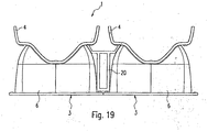
- Fig. 19 variant shown is to use a profile part 20, which has both sides arranged snap arms for latching with raster modules 3. This makes it possible to form on both sides of the central profile element 20 lighting grid and accordingly to realize two- or multi-lamp lights.
- corresponding grooves are provided in the raster modules to receive corresponding covers. These grooves can also be provided to snap receiving elements - for example, bow-like spring elements - for mounting the lamp to a ceiling.
- the luminaire according to the present invention is thus distinguished by its simple construction, which makes it possible to provide luminaires in different variants and lengths by means of slight changes to the individual components. At the same time optically extremely appealing lighting effects can be achieved and the lamp can be given a high-quality appearance.
Description
Die vorliegende Erfindung betrifft eine Leuchte mit einem Raster, welches zur Lichtabstrahlung vorgesehene Durchtrittsöffnungen aufweist.The present invention relates to a luminaire with a grid, which has openings provided for the emission of light.
In Büros oder an sonstigen Arbeitsplätzen werden zur Beleuchtung üblicherweise Leuchten mit länglichen, stabförmigen Lichtquellen, beispielsweise Leuchtstoffröhren, eingesetzt. Um eine auch die Arbeit an Bildschirmarbeitsplätzen nicht beeinträchtigende Ausleuchtung des Raumes zu erzielen und dabei insbesondere Blendeffekte zu vermeiden, sind in Abstrahlrichtung gesehen vor der Lampe Raster angeordnet, mit deren Hilfe der Lichtaustritt auf einen vorgegebenen Bereich eingeschränkt wird. Die Verwendung von Leuchtstofflampen gewährleistet dabei eine hohe Lichtausbeute bei einem verhältnismäßig geringen Energiebedarf.In offices or other workplaces lights are usually used for lighting with elongated, rod-shaped light sources, such as fluorescent tubes. In order to achieve a work on screen workplaces not impairing illumination of the room and in particular to avoid glare, are arranged in the emission direction in front of the lamp grid arranged with the help of the light emission is limited to a predetermined range. The use of fluorescent lamps ensures a high light output with a relatively low energy consumption.
Üblicherweise besteht eine derartige Rasterleuchte aus einem länglichen Leuchtengehäuse, welches in seinen Stirnbereichen Lampenfassungen zum Halten und elektrischen Anschließen zumindest einer länglichen Lampe aufweist. Das Gehäuse, welches darüber hinaus in der Regel auch ein Betriebsgerät für die Lampe - beispielsweise ein elektronisches Vorschaltgerät - aufnimmt, weist in seinem unteren Bereich ferner Halteelemente auf, mit deren Hilfe ein Leuchtenraster in Abstrahlrichtung gesehen vor der Lampe angeordnet und befestigt werden kann. Bei dem Raster handelt es sich üblicherweise um ein einstückiges Element, welches auf die Unterseite des Leuchtengehäuses bzw. auf die dort vorgesehenen Befestigungs- oder Haltemittel aufgeschnappt wird.Usually, such a grid lamp consists of an elongated lamp housing, which has lamp holders for holding and electrical connection of at least one elongate lamp in its end regions. The housing, which also usually also an operating device for the lamp - for example, an electronic ballast - receives, has in its lower part further holding elements, with the aid of a luminous grid seen in the emission can be arranged and fixed in front of the lamp. The grid is usually a one-piece element, which is snapped onto the underside of the lamp housing or on the fastening or holding means provided there.
Gasentladungslampen, insbesondere die zur normalen Raumbeleuchtung vorwiegend eingesetzten Leuchtstofflampen sind in unterschiedlichen Längen erhältlich. Um Leuchten des gleichen Typs zur Verfügung stellen zu können, in denen jeweils eine Lampe unterschiedlicher Länge zum Einsatz kommen kann, ist es erforderlich, Leuchtengehäuse sowie Leuchtenraster in den entsprechenden Längen bereitzustellen, wobei die Herstellung dieser Elemente in unterschiedlichen Längen allerdings mit einem erhöhten Kostenaufwand verbunden ist.Gas discharge lamps, in particular the fluorescent lamps mainly used for normal room lighting are available in different lengths. In order to provide luminaires of the same type, in each of which a lamp of different lengths can be used, it is necessary to provide luminaire housing and luminaire grid in the corresponding lengths, the production of these elements in different lengths, however, associated with an increased cost is.
Die Bereitstellung zumindest von Leuchtenrastern in unterschiedlichen Längen wird durch Lösungen vereinfacht, welche in der
Um eine zumindest zu einem gewissen Grad stabile Rasteranordnung zu erhalten müssen dann die einzelnen Module mittels zusätzlicher Elemente zusammengehalten werden. Bei der
Der vorliegenden Erfindung liegt deshalb die Aufgabe zugrunde, eine kostengünstige Alternative zur Herstellung von Leuchten der oben beschriebenen Art anzugeben. Gleichzeitig sollen die Leuchten jedoch ansprechend aussehen und sehr hochwertig wirken.The present invention is therefore based on the object of specifying a cost-effective alternative to the production of luminaires of the type described above. At the same time, however, the luminaires should look appealing and have a very high-quality effect.
Die Aufgabe wird durch eine Leuchte mit den Merkmalen des Anspruches 1 gelöst.The object is achieved by a luminaire with the features of claim 1.
Die erfindungsgemäße Leuchte weist Mittel zum Halten und zum elektrischen Anschließen einer rohrförmigen Lampe sowie mehrere - in Abstrahlrichtung gesehen - vor der Lampe angeordnete Rastermodule auf, welche jeweils zur Lichtabstrahlung vorgesehene Durchtrittsöffnungen aufweisen. Die Rastermodule sind dabei hintereinander zu einem länglichen Leuchtenraster angeordnet und über Halteelemente zusammengehalten, wobei erfindungsgemäß die Halteelemente durch seitlich auf die Rastermodule aufschnappbare Profilelemente in Form von Verbindungsprofilen gebildet sind.The luminaire according to the invention has means for holding and for electrically connecting a tubular lamp and a plurality of grid modules arranged in front of the lamp, viewed in the emission direction, which have respective passage openings provided for the emission of light. The grid modules are arranged one behind the other to form an elongated luminaire grid and held together by holding elements, wherein according to the invention the holding elements are formed by profile elements which can be snapped onto the grid modules in the form of connecting profiles.
Die erfindungsgemäße Lösung sieht vor, ein Leuchtenraster aus mehreren einzelnen Rastermodulen zu bilden, die für sich allein genommen verhältnismäßig kurz sind und gemeinsam zu dem Raster geeigneter Länge angeordnet bzw. zusammengesetzt werden. Hierdurch besteht die Möglichkeit, lediglich ein einziges Rastermodul einer vorgegebenen Länge zur Verfügung zu stellen, welches mit mehreren gleichartigen Modulen zu Leuchtenrastern in den gewünschten Längen zusammengebaut wird. Beispielsweise können Rastermodule mit einer Länge von 300 mm zur Verfügung gestellt werden, die zu den üblichen Längen von 600, 1200 und 1500 mm zusammengefügt werden. Die Kosten können hierdurch erheblich reduziert werden, da für die Rastermodule, die vorzugsweise im Kunststoff-Spritzgussverfahren hergestellt werden, lediglich ein einziges Werkzeug erforderlich ist. Die beträchtlichen Kosten für Werkzeuge in weiteren Längen können durch die vorliegende Erfindung eingespart werden.The solution according to the invention provides for a luminaire grid to be formed from a plurality of individual grid modules which, taken on their own, are relatively short and are arranged or assembled together to form the grid of suitable length. This makes it possible to provide only a single raster module of a given length available, which is assembled with several similar modules to light grids in the desired lengths. For example, grid modules with a length of 300 mm can be provided, which are assembled to the usual lengths of 600, 1200 and 1500 mm. The costs can thereby be considerably reduced because only a single tool is required for the raster modules, which are preferably produced by plastic injection molding. The considerable cost of tools in further lengths can be saved by the present invention.
Das Zusammenhalten der verschiedenen Rastermodule zu einem einzigen Leuchtenraster erfolgt erfindungsgemäß mittels seitlich aufschnappbarer Profilelemente. Diese Profilelemente können sehr schlank sein und werden im Verbund mit den Rastermodulen stabilisiert, so dass sich insgesamt eine sehr stabile Anordnung ergibt. Damit können die Profilelemente sogar das üblicherweise erforderliche Leuchtengehäuse ersetzen, wodurch weitere Kosten eingespart werden. Im Unterschied zu den aus dem Stand der Technik bekannten Lösungen kann ferner das Zusammensetzen mehrere Module zu einem einzigen Leuchtenraster über das seitliche Aufschnappen der Profilelemente deutlich einfacher und schneller erfolgen.The holding together of the various grid modules to a single luminaire grid is carried out according to the invention by means of laterally aufschnappbarer profile elements. These profile elements can be very slim and are stabilized in conjunction with the grid modules, so that the overall result is a very stable arrangement. Thus, the profile elements can even replace the usually required luminaire housing, whereby further costs can be saved. In contrast to the solutions known from the prior art, moreover, the assembly of a plurality of modules into a single luminaire grid via the lateral snap-fastening of the profile elements can take place much more easily and quickly.
Wesentlich ist ferner, dass die Leuchte auch zur indirekten Beleuchtung verwendet werden kann, d.h., ein Teil des von der Lampe abgegebenen Lichts wird entgegen der Haupt-Lichtabstrahlrichtung zur Oberseite hin abgegeben, um beispielsweise die Decke aufzuhellen. In diesem Fall ist die Verwendung der lediglich seitlich aufschnappbaren Profilelemente sogar besonders vorteilhaft, da im Gegensatz zu einem herkömmlichen Leuchtengehäuse, welches in der Regel im Schnitt gesehen U-förmig gestaltet ist, keine partiellen Löcher in den Gehäuseboden gestanzt oder gefräst werden müssen, welche den indirekten Lichtaustritt ermöglichen. Gleichzeitig wird durch die Verwendung der lediglich seitlich angeordneten Profilelemente das Zu- und Abführen elektrischer Leitungen vereinfacht.It is also essential that the luminaire can also be used for indirect lighting, ie a part of the light emitted by the lamp is emitted against the main light emission direction to the top, for example, to lighten the ceiling. In this case, the use of only laterally aufschnappbaren profile elements even particularly advantageous because in contrast to a conventional luminaire housing, which is usually designed in section U-shaped, no partial holes must be stamped or milled into the housing bottom, which the allow indirect light emission. At the same time the supply and removal of electrical lines is simplified by the use of only laterally disposed profile elements.
Die zu dem Leuchtenraster zusammengesetzten einzelnen Rastermodule bestehen vorzugsweise - wie bereits erwähnt - aus Kunststoff. Dies hat zur Folge, dass sich die einzelnen Module infolge der auftretenden Temperaturunterschiede geringfügig ausdehnen und zusammenziehen können. Hierdurch könnte zwischen den einzelnen Rastermodulen ein schmaler Spalt entstehen, durch den Licht austreten kann, was den optischen Eindruck der Leuchte beeinträchtigt. Um dies zu verhindern, werden erfindungsgemäß die Rastermodule durch an den Längsenden des Leuchtenrasters vorgesehene stirnseitige Federn, durch elastische Bänder oder dergleichen in Längsrichtung zusammengedrückt. Hierdurch ist sichergestellt, dass die einzelnen Rastermodule selbst nach Temperaturschwankungen noch aneinander anliegen und kein unerwünschter Lichtaustritt stattfindet.The individual grid modules assembled to form the luminaire grid preferably consist - as already mentioned - of plastic. This has the consequence that the individual modules can expand and contract slightly as a result of the temperature differences that occur. This could create a narrow gap between the grid modules, can escape through the light, which affects the visual appearance of the lamp. In order to prevent this, the grid modules according to the invention are compressed by provided at the longitudinal ends of the luminaire grid frontal springs, by elastic bands or the like in the longitudinal direction. This ensures that the individual raster modules still abut each other even after temperature fluctuations and no unwanted light emission takes place.
Das erfindungsgemäße Zusammenhalten der Rastermodule durch die seitlichen Profilelemente erfolgt vorzugsweise mit Hilfe von Führungsnuten und/oder Schnappnasen, welche ein Verrasten der einzelnen Elemente miteinander ermöglichen. Die Profilelemente können dabei eine größere Höhe als die Rastermodule selbst aufweisen, wodurch oberhalb des Leuchtenrasters ein von den Profilelementen umschlossener bzw. seitlich abgedeckter Raum gebildet wird, der beispielsweise zur Aufnahme von Lampenbetriebsgeräten genutzt werden kann. Eine andere Möglichkeit besteht auch darin, die seitlichen Profilelemente im Querschnitt U-förmig auszubilden, wodurch neben dem Leuchtenraster ein Raum geschaffen wird, in dem entsprechende Lampenbetriebsgeräte angeordnet werden können.The holding together of the raster modules by the lateral profile elements according to the invention is preferably carried out with the aid of guide grooves and / or snap lugs, which allow a locking of the individual elements together. The profile elements can have a greater height than the grid modules themselves, which above the luminaire grid is formed by a space enclosed by the profile elements or laterally covered space, which can be used for example for receiving lamp operating devices. Another possibility is to form the lateral profile elements in cross-section U-shaped, which in addition to the luminaire grid a space is created in the corresponding lamp operating devices can be arranged.
Bei einer weiteren Variante der vorliegenden Erfindung weist die Leuchte zwei seitlich nebeneinander angeordnete Leuchtenraster der oben beschriebenen Art auf, welche über ein dazwischen angeordnetes Verbindungsprofil miteinander verbunden sind. Insgesamt wird somit die Möglichkeit geschaffen, eine Rasterleuchte auf eine sehr einfache und kostengünstige Art und Weise herzustellen.In a further variant of the present invention, the luminaire has two laterally juxtaposed light grids of the type described above, which are connected to one another via a connecting profile arranged therebetween. Overall, therefore, the possibility is created to produce a grid lamp in a very simple and inexpensive manner.
Eine andere vorteilhafte Weiterbildung der vorliegenden Erfindung betrifft die Ausgestaltung der einzelnen Rastermodule. Vorzugsweise weisen diese jeweils einen sich in Längsrichtung erstreckenden Rückreflektor auf, der dazu bestimmt ist, einen Teil des von der Lampe abgestrahlten Lichts entgegen der Abstrahlrichtung zu reflektieren. Darüber hinaus sind in dem Rückreflektor Durchtrittsöffnungen angeordnet, welche dazu bestimmt sind, einen Teil des von der Lampe abgestrahlten Lichts in Abstrahlrichtung hindurchtreten zu lassen. An diese Durchtrittsöffnungen können sich zusätzlich in Abstrahlrichtung Topfreflektoren anschließen.Another advantageous development of the present invention relates to the design of the individual raster modules. Preferably, these each have a longitudinally extending back reflector, which is intended to reflect a part of the light emitted by the lamp against the emission direction. In addition, passage openings are arranged in the back reflector, which are intended to pass a part of the light emitted by the lamp in the emission direction. In addition, in the direction of radiation, pot reflectors can be connected to these openings.
Der Grundgedanke dieser besonderen Ausgestaltung der einzelnen Rastermodule besteht darin, das Licht einer einzigen rohrförmigen Lampe über eine Vielzahl von Lichtaustrittsöffnungen, an die sich topfförmige Reflektoren anschließen, abzustrahlen. Hierdurch wird der Eindruck einer Reihenanordnung von einzelnen Halogenstrahlen erzielt, wodurch den Leuchten ein besonders hochwertiges Aussehen verliehen wird. Gleichzeitig können, wie nachfolgend noch erläutert werden wird, eine Vielzahl von ansprechenden lichttechnischen Effekten erzielt werden. Darüber hinaus zeichnet sich ein entsprechendes Rastermodul durch seinen einfachen Aufbau aus, da die aus dem Rückreflektor und den Topfreflektoren bestehende Anordnung einstückig ausgebildet werden kann, was - wie bereits zuvor erwähnt - dadurch erreicht wird, dass die Rastermodule im Spritz-Gießverfahren hergestellt werden.The basic idea of this particular embodiment of the individual grid modules is to emit the light of a single tubular lamp via a plurality of light exit openings, followed by cup-shaped reflectors. As a result, the impression of a series arrangement of individual halogen beams is achieved, whereby the lights are given a particularly high-quality appearance. At the same time, as will be explained below, a variety of appealing lighting effects can be achieved. In addition, a corresponding grid module is characterized by its simple structure, since the arrangement consisting of the back reflector and the pot reflectors can be formed in one piece, which - as already mentioned above - is achieved in that the grid modules are produced by injection molding.
Eine vorteilhafte Weiterbildung dieser Variante besteht dann darin, dass die Topfreflektoren an deren Randbereichen über eine parallel zur Lampe angeordnete Verbindungsplatte miteinander verbunden sind, wobei die Verbindungsplatte ebenfalls einstückig mit den Reflektoren bzw. dem gesamten Rästermodul verbunden sein kann. Ein besonders ansprechender optischer Effekt kann in diesem Fall dadurch erzielt werden, dass die Verbindungsplatte selbst transparent ausgestaltet ist. Wird nämlich ein Teil des von der rohrförmigen Lampe abgestrahlten Lichts in einen Bereich außerhalb der Topfreflektoren gelenkt, so ist deren Struktur durch die transparente Verbindungsplatte erkennbar. Das Einbringen des Lichts in den Bereich außerhalb der Topfreflektoren kann beispielsweise dadurch erreicht werden, dass der Rückreflektor zumindest teilweise lichtdurchlässig ist. Ferner besteht die Möglichkeit, den Rückreflektor in seinen transparenten Bereichen einzufärben, so dass die Verbindungsplatte in einem geänderten Farbton erscheint. Die Topfreflektoren können dabei mit ihren Lichtaustrittsöffnungen über die Verbindungsplatte hinausragen oder bündig zu dieser enden.An advantageous development of this variant is then that the pot reflectors are connected to each other at their edge regions via a connecting plate arranged parallel to the lamp, wherein the connecting plate may also be integrally connected to the reflectors or the entire Räserermodul. A particularly appealing optical effect can be achieved in this case, that the connecting plate itself is designed to be transparent. Namely, when a part of the light emitted from the tubular lamp is directed into an area outside the pot reflectors, the structure thereof can be recognized by the transparent connecting plate. The introduction of the light into the area outside the pot reflectors can be achieved, for example, by virtue of the fact that the back reflector is at least partially translucent. It is also possible to color the back reflector in its transparent areas, so that the connection plate appears in a changed color. The pot reflectors can protrude with their light exit openings on the connection plate or ends flush with this.
Der Rückreflektor ist vorzugsweise derart ausgebildet, dass er die Lampe zumindest teilweise umgreift. Insbesondere kann er im Querschnitt gesehen halbkreisförmig ausgebildet sein.The rear reflector is preferably designed such that it at least partially surrounds the lamp. In particular, it can be semicircular, as seen in cross-section.
Ein anderer Vorteil der besonders ausgestalteten Rastermodule besteht auch darin, dass ein Teil des von der Lampe abgegebenen Lichts zur Indirektbeleuchtung verwendet wird. Insbesondere könnte vorgesehen sein, an der den Topfreflektoren gegenüberliegenden Seite der Lampe eine Abblend- oder Filterplatte vorzusehen, über die ein Teil des von der Lampe abgegebenen Lichts auf die Decke des zu beleuchtenden Raumes gerichtet ist. Die Randbereiche dieser Abblend- oder Filterplatte können hingegen reflektierend ausgebildet sein, um die Umlenkung eines Teils des Lichts in den die Topfreflektoren umgebenden Raum zu ermöglichen. Auch hierbei besteht die Möglichkeit, den lichtdurchlässigen Bereich der Abblend- oder Filterplatte farbig zu gestalten und damit den Deckenbereich oberhalb der Lampe in einem anderen Farbton erscheinen zu lassen.Another advantage of the specially designed raster modules is also that part of the light emitted by the lamp is used for indirect illumination. In particular, it could be provided to provide on the side opposite the pot reflectors side of the lamp, a Abblend- or filter plate over which a part of the output from the lamp Light is directed to the ceiling of the room to be illuminated. On the other hand, the edge regions of this screening or filter plate can be designed to be reflective in order to allow the deflection of part of the light into the space surrounding the pot reflectors. Again, it is possible to make the translucent area of the screening or filter plate colored and thus to make the ceiling area appear above the lamp in a different color.
Im folgenden soll die Erfindung anhand der beiliegenden Zeichnung näher erläutert werden. Es zeigen:
- Fig. 1
- ein erstes Ausführungsbeispiel einer erfindungsgemäßen Leuchte in perspektivi-scher Ansicht;
- Fig. 2
- die in
Figur 1 dargestellte Leuchte im Schnitt; - Fig. 3
- ein bevorzugtes Rastermodul zum Bilden eines Leuchtenrasters perspektivischer Ansicht;
- Fig. 4
- die Unterseite des Rastermoduls;
- Fig. 5
- eine erste Variante der erfindungsgemäßen Leuchte;
- Fig. 6
- eine zweite Variante der erfindungsgemäßen Leuchte;
- Fig. 7
- eine dritte Variante der erfindungsgemäßen Leuchte, die zur Befestigung an einer Tragschiene vorgesehen ist;
- Fig. 8
- eine vierte Variante der erfindungsgemäße Leuchte mit zwei rohrförmigen Lampen;
- Fig. 9
- ein weiteres Ausführungsbeispiel einer erfindungsgemäßen Leuchte;
- Fig. 10a, b
- verschiedene Verwendungsmöglichkeiten für die in
Fig. 9 dargestellte Leuchte; - Fig. 11
- ein weiteres Ausführungsbeispiel für ein Rastermodul mit quadratischen Topfreflektoren;
- Fig. 12
- das Rastermodul der in
Fig. 11 dargestellten Leuchte; - Fig. 13
- die Stirnansicht eines Rastermoduls mit seitlich aufschnappbaren Profilelementen;
- Fig. 14
- eine perspektivische Ansicht der Anordnung gemäß
Fig. 13 ; - Fig. 15
- zwei in Längsrichtung hintereinander angeordnete und zu einem Leuchtenraster zusammengefügte Rastermodule;
- Fig. 16
- zwei in Längsrichtung hintereinander geschaltete und durch eine Schnappverbindung zusammengefügte Rastermodule.;
- Fig. 17
- eine perspektivische Ansicht des Stirnendes eines aus mehreren hintereinandergeschalteten Rastermodulen bestehenden Leuchtenrasters mit Federelementen zur Aufbringung eines in Längsrichtung wirkenden Verbindungsdrucks;
- Fig. 18
- die Stirnansicht eines Rastermoduls mit einem U-förmigen Seitenprofil; und
- Fig. 19
- zwei seitlich nebeneinander angeordnete Leuchtenraster.
- Fig. 1
- a first embodiment of a lamp according to the invention in perspektivi-shear view;
- Fig. 2
- in the
FIG. 1 illustrated light in section; - Fig. 3
- a preferred raster module for forming a light grid perspective view;
- Fig. 4
- the bottom of the raster module;
- Fig. 5
- a first variant of the lamp according to the invention;
- Fig. 6
- a second variant of the lamp according to the invention;
- Fig. 7
- a third variant of the lamp according to the invention, which is provided for attachment to a mounting rail;
- Fig. 8
- a fourth variant of the lamp according to the invention with two tubular lamps;
- Fig. 9
- a further embodiment of a lamp according to the invention;
- Fig. 10a, b
- different uses for the in
Fig. 9 illustrated light; - Fig. 11
- a further embodiment of a raster module with square pot reflectors;
- Fig. 12
- the raster module of in
Fig. 11 illustrated light; - Fig. 13
- the front view of a grid module with side aufschnappbaren profile elements;
- Fig. 14
- a perspective view of the arrangement according to
Fig. 13 ; - Fig. 15
- two arranged in the longitudinal direction one behind the other and assembled into a luminaire grid grid modules;
- Fig. 16
- two raster modules connected one after the other in the longitudinal direction and joined together by a snap connection;
- Fig. 17
- a perspective view of the front end of a plurality of series-connected grid modules luminaire grid with spring elements for applying a longitudinally acting connection pressure;
- Fig. 18
- the front view of a raster module with a U-shaped side profile; and
- Fig. 19
- two side by side arranged light grid.
Die
Die in
Die Topfreflektoren 6 schließen sich an Durchtrittsöffnungen des Rückreflektors 4 an, so daß ein Teil des von der Lampe 2 abgestrahlten Lichts über diese Durchtrittsöffnungen und die Topfreflektoren 6 nach unten gerichtet wird. Die Topfreflektoren 6 dienen somit zur Direktbeleuchtung des unterhalb der Leuchte 1 liegenden Raumes und haben eine Form, durch die das von der Lampe 2 nach unten abgestrahlte Licht auf einen vorgegebenen Austrittswinkel begrenzt wird. Da auf diese Weise Blendeffekte vermieden werden, kann die erfindungsgemäße Leuchte 1 insbesondere auch zur Raumbeleuchtung an Büroarbeitsplätzen eingesetzt werden.The
Zu beiden Seiten des Leuchtenrasters befinden sich über die Länge der Lampe 2 erstreckende Seitenkästen 10, von denen einer zur Lagerung eines Betriebsgerätes 11 für die Lampe 2 dient. Bei diesem Betriebsgerät 11 kann es sich insbesondere um ein elektronisches Vorschaltgerät zum Betreiben einer Gasentladungslampe, insbesondere einer Leuchtstoffröhre handeln, auf die Darstellung der Fassungen zum Halten und elektrischen Anschließen der Lampe 2 wurde aus Gründen der Übersicht verzichtet.On both sides of the luminaire grid are located over the length of the
Wie später noch ausführlicher erläutert wird, dienen die Seitenkästen 10 als Halteelemente auch dazu, die hintereinander angeordneten Rastermodule 3 zu dem Leuchtenraster zusammenzuhalten. Die Befestigung der beiden Seitenkästen 10 an den Rastermodulen 3 erfolgt im dargestellten Beispiels mit Hilfe von Seitenstegen 9, die von den Außenseiten des Rückreflektors 4 hervorstehen, sowie einer parallel zu diesen Seitenstegen 9 angeordneten Verbindungsplatte 8. Diese Verbindungsplatte 8 verbindet die Topfreflektoren 6 an ihren Randbereichen, wobei die Topfreflektoren 6 mit ihren Lichtaustrittsöffnungen 7 gegenüber der Verbindungsplatte 8 ein wenig hervorstehen. Die Verbindungsplatte 8 und die Seitenstege 9 dienen darüber hinaus auch zur Erzeugung besonderer lichttechnischer Effekte, wie ebenfalls später noch erläutert wird.As will be explained in more detail later, serve the
Neben der über die Topfreflektoren 6 erzielten Direktbeleuchtung wird ein Teil des von der Lampe 2 abgegebenen Lichts auch über den Rückreflektor 4 nach oben gelenkt und dient dementsprechend zur indirekten Raumbeleuchtung. Dabei besteht die Möglichkeit, das Verhältnis zwischen der Direktbeleuchtung über die Topfreflektoren 6 und der Indirektbeleuchtung über den Rückreflektor 4 durch eine Veränderung der Lampenposition bezüglich des Rückreflektors 4 zu variieren. Hierdurch können die lichttechnischen Eigenschaften der Leuchte 1 an äußere Verhältnisse angepaßt werden.In addition to the direct illumination achieved via the
Ein Rastermodul 3 mit dem Rückreflektor 4 und den Topfreflektoren 6 wird vorzugsweise durch ein einziges Teil gebildet, das beispielsweise durch Spritzgießen hergestellt wird. Dabei kann das Rastermodul 3 im Idealfall mit einem einfach gestalteten, schieberlosen Formwerkzeug hergestellt werden, bei komplexeren Strukturen wird das Werkstück mittels Schiebertechnik entformt. Auch die Verbindungsplatte 8 ist Bestandteil dieses einstückigen Kunststoffteils, das in vergrößerter Darstellung in den
Wie der Darstellung in
Um den Eindruck, daß es sich um eine Reihenanordnung einzelner Halogenstrahler handelt, zu verstärken, kann vorgesehen sein, die Innenseite der Topfreflektoren 6 facettenartig zu gestalten. Das Erzeugen der einzelnen Facetten erfolgt bereits bei der Herstellung des Kunststoffteils während des Spritzgießens und wird durch eine entsprechende Gestaltung der Formwerkzeuge erreicht. Das Aufbringen der Reflexionsschicht erfolgt vorzugsweise durch Aufdampfen einer Aluminiumbeschichtung im Hochvakuum.To reinforce the impression that it is a series arrangement of individual halogen lamps, it can be provided to make the inside of the
Besondere lichttechnische Effekte können bei der Leuchte 1 mit den bevorzugten Rastermodulen 3 dadurch erzeugt werden, daß die verschiedenen Bereiche der Rastermodule 3 unterschiedlich reflektierend bzw. lichtdurchlässig ausgebildet sind. Dies soll im folgenden anhand der
Gegenüber der in
Der zuvor beschriebene Effekt der Aufhellung der Außenseiten der Topfreflektoren 6 wird auch bei der in
Eine Weiterbildung der in
Die erfindungsgemäße Leuchte kann auch zur Montage an einer Tragschiene 16 vorgesehen sein, wie dies bei der in
Die in
Die Form der Topfleuchten kann grundsätzlich beliebig gewählt werden. Bei dem in
Die Reflexionsfähigkeit der einzelnen Bereiche der eines Rastermoduls 3 kann individuell gestaltet werden. So können beispielsweise die Topfreflektoren 6 an ihrer Innenseite sehr glatt gestaltet werden, so daß beim Bedampfen eine Hochglanzschicht entsteht, während hingegen die die Topfreflektoren 6 umgebende Verbindungsplatte 8 etwas gröber strukturiert werden kann, so daß sich eine matte Schicht ergibt. Dies kann bereits beim Gestalten des Spritzgußwerkzeugs berücksichtigt werden, so daß kein Nachbearbeiten des Kunststoffwerkstückes notwendig ist.The reflectivity of the individual regions of a
Das aus den besonderen Rastermodulen zusammengesetzte Leuchtenraster zeichnet sich somit durch die Vielfalt der damit zu erzielenden Beleuchtungseffekte aus, die jedoch keine Auswirkungen auf die Funktionsfähigkeit der Leuchte in der Raumbeleuchtung bzw. der Beleuchtung von Arbeitsplätzen haben. Mit anderen Worten, die Leuchte ist trotz der verschiedenen optischen Effekte nach wie vor in der Lage, Büroräume in geeigneter Weise auszuleuchten.The assembled from the special grid modules luminaire grid is thus characterized by the variety of lighting effects to be achieved with it, but have no effect on the functionality of the lamp in the room lighting or lighting of workplaces. In other words, despite the various optical effects, the luminaire is still able to illuminate offices appropriately.
Anhand der nachfolgenden
Vorzugsweise werden die Rastermodule 3 in einer einzigen Länge von 300 mm in Kunststoff gespritzt. Diese einzelnen Rastermodule 3 können dann zu Leuchtenrastern in den üblichen Längen von 600 1200 und 1500 mm zusammengefügt werden. Gemäß der Darstellung in den
Die Profile 20 können sehr schlank sein, sie werden dann im aufgeschnappten Zustand in Verbindung mit den einzelnen Rastermodulen 3 stabilisiert, wodurch sich insgesamt gesehen eine verhältnismäßig stabile Anordnung ergibt. Wesentlich ist hierbei auch, wie den Darstellungen in den
Anstelle des Aufschnappens könnten die seitlichen Profile 20 auch aufgeschoben werden. Je nach Montageart sind entsprechende Verbindungselemente 201, 202 in Form von Führungsnuten oder Schnappnasen vorzusehen, die sich über die gesamte Länge der Profile 20 erstrecken können. Hierbei ist wesentlich, dass die für das Halten der Rastermodule 3 verantwortlichen Verbindungselemente 201, 202 zumindest an den jeweiligen Endbereichen der Rastermodule 3 vorgesehen sind, weil erst eine Fixierung in diesen Endbereichen zu der notwendigen Stabilität der gesamten Anordnung führt. Mit anderen Worten, es ist zu vermeiden, dass die Profile 20, die bevorzugt aus Aluminium stranggepresst werden, sich verbiegen können.Instead of snapping the side profiles 20 could also be postponed. Depending on the type of installation, corresponding connecting
Zur Erhöhung der Stabilität trägt auch bei, dass die Rastermodule 3 an ihren jeweiligen Stirnseiten über ihre ganze Bauhöhe hinweg aneinander anliegen. Zusätzlich können die Rastermodule 3 in diesen Bereichen miteinander verklebt oder verschweißt werden, wie dies in
Durch das zuvor beschriebene Verbinden der einzelnen Rastermodule 3 miteinander wird die Stabilität des gesamten Leuchtenrasters zwar erhöht, es ist allerdings nicht zwingend erforderlich. Werden die Rastermodule 3 lediglich lose aneinandergefügt, ergibt sich allerdings aus der Tatsache, dass die Rastermodule 3 aus Kunststoff bestehen, ein anderes Problem. Da die Rastermodule 3 im Laufe der Zeit recht unterschiedlichen Temperaturen ausgesetzt sein können, muss berücksichtigt werden, dass sie sich teilweise zusammenziehen oder ausdehnen können. Hierdurch könnte zwischen den Stirnseiten der einzelnen Rastermodule 3 Spalte oder Freiräume entstehen, durch die Licht austreten kann, wodurch allerdings der optische Eindruck der Leuchte beeinträchtigt wird. Um dieses Problem zu umgehen, sind bei dem in
Bei den bisherigen Ausführungsbeispielen war davon ausgegangen worden, dass die Rastermodule 3 mit ihren jeweiligen Stirnseiten unmittelbar aneinander anliegen um das Leuchtenraster zu bilden. Tatsächlich können die einzelnen Module 3 allerdings auch bewußt voneinander beabstandet angeordnet werden.In the previous embodiments, it was assumed that the
Eine kostengünstige Arbeitsplatzleuchte mit direkter und indirekter Lichtabgabe gemäß der vorliegenden Erfindung würde dann beispielsweise ähnlich wie die in
Die Geräteeinheit besteht im wesentlichen aus einer Montageplatte sowie den Betriebsgeräten und ggf. aus den Aufnahmeelementen für die Montage der Leuchte 1 an der Decke. Bevorzugt wird die Montageplatte derart ausgestaltet, dass diese mit den Profilteilen 20 zusammenpasst, also ähnlich wie die Rastermodule 3 Schnappnasen oder dergleichen aufweist, die mit den Schnapparmen der Profile 20 zusammenwirken. Auch bei dieser Variante kann das Aufbringen eines axialen Drucks entsprechend der Anordnung in
Die Profilteile 20 bilden somit gleichzeitig auch die Außenwand des Leuchtengehäuses. Es versteht sich von selbst, dass die Außenseiten der Profile 20 verschiedenartig gestaltet werden können. Beispielsweise können Rillen oder Rippen vorgesehen sein oder die Außenseite kann auch ganz einfach glatt ausgestaltet werden. Durch unterschiedliche Beschichtungsverfahren könnte die Oberfläche der Profile 20 auch farblich gestaltet werden. Vorzugsweise wird hierfür das Verfahren der Pulverbeschichtung verwendet.The
Eine andere denkbare Variante besteht darin, dass auf die Profile 20 weitere Außenprofile aufgebracht werden, die nicht unbedingt aus Metall bestehen müssen. Diese Außenprofile werden vorzugsweise wiederum auf die Halteprofile 20 aufgeschnappt und bilden letztendlich die Außenwand des Leuchtengehäuses.Another conceivable variant is that 20 further outer profiles are applied to the profiles, which need not necessarily be made of metal. These outer profiles are preferably again snapped onto the retaining
Eine andere - nicht dargestellte Variante - der erfindungsgemäßen Leuchte besteht darin, die L-förmigen Profile 20 deutlich höher auszugestalten, als die Rastermodule 3. In diesem Fall wird oberhalb der Rastermodule 3 ein von den Seitenprofilen 20 seitlich abgedeckter Freiraum geschaffen, der ebenfalls zur Lagerung der von Lampenbetriebsgeräten benutzt werden kann. Wird dabei das Betriebsgerät in der Mitte der Leuchte 1 angeordnet, so können die Enden der Leuchte derart ausgestaltet werden, dass Licht sowohl direkt in Richtung der zu beleuchtenden Fläche als auch - nunmehr allerdings lediglich in den Endbereichen der Leuchte - indirekt zur Decke hin austreten kann.Another - not shown variant - of the lamp according to the invention is to design the L-shaped
Eine letzte, in
Um den hochwertigen Eindruck der Leuchte anzuheben, hat sich gezeigt, dass es erforderlich ist, insbesondere einzelne Zellen bzw. Topfreflektoren der Rastermodule abzudecken. Hierbei handelt es sich insbesondere um diejenigen Lichtaustrittsöffnungen, über denen die Fassungen der Lampen angeordnet sind, da in diesen Bereichen eine gleichmäßige Lichtabstrahlung nicht erzielt werden kann. Vorzugsweise werden deshalb in den Rastermodulen entsprechende Nuten vorgesehen, um entsprechende Abdeckungen aufzunehmen. Diese Nuten können auch dazu vorgesehen sein, Aufnahmeelemente - beispielsweise bügelartige Federelemente - für die Montage der Leuchte an einer Decke einzuschnappen.In order to increase the high-quality impression of the luminaire, it has been found that it is necessary in particular to cover individual cells or pot reflectors of the raster modules. These are in particular those light exit openings, over which the sockets of the lamps are arranged, since in these areas a uniform light emission can not be achieved. Preferably, therefore, corresponding grooves are provided in the raster modules to receive corresponding covers. These grooves can also be provided to snap receiving elements - for example, bow-like spring elements - for mounting the lamp to a ceiling.
Die Leuchte gemäß der vorliegenden Erfindung zeichnet sich somit durch ihre einfache Bauweise aus, die es ermöglicht, durch geringfügige Veränderungen an den einzelnen Bauteilen Leuchten in unterschiedlichen Varianten und Längen zur Verfügung zu stellen. Gleichzeitig können optisch äußert ansprechenden lichttechnische Effekte erzielt und der Leuchte ein hochwertiges Aussehen verliehen werden.The luminaire according to the present invention is thus distinguished by its simple construction, which makes it possible to provide luminaires in different variants and lengths by means of slight changes to the individual components. At the same time optically extremely appealing lighting effects can be achieved and the lamp can be given a high-quality appearance.
Claims (32)
- A luminaire, with
means for holding and for electrically connecting a tubular lamp (2),
and
several - seen in the emission direction- grid-type modules (3) arranged in front of the lamp (2),
wherein the grid-type modules (3) are arranged and held together to form an elongated luminaire grid,
wherein the grid-type modules (3) are held together by holding elements (20), characterized in
that the grid-type modules (3) each have through-openings (5) provided for the light emission, and
that the holding elements (20) are formed by profile elements in the form of connection profiles, which can be laterally snapped onto the grid-type modules (3),
wherein the grid-type modules (3) forming the luminaire grid are pressed together in the longitudinal direction by end-face springs provided on the longitudinal ends of the luminaire grid, by elastic bands or the like. - A luminaire according to Claim 1,
characterized in
that the lateral profile elements have a greater height than the grid-type modules (3) and thus include a space for accommodating lamp operating devices (11) above the luminaire grid. - A luminaire according to Claim 1,
characterized in
that the lateral profile elements have a U-shaped cross section and thus include a space for accommodating lamp operating devices located laterally next to the luminaire grid. - A luminaire according to any one of Claims 1 to 3,
characterized in
that connecting elements (201, 202) are provided on the grid-type modules (3) and/or the holding elements (20). - A luminaire according to Claim 4,
characterized in
that the connecting elements (201, 202) are snap-action lugs arranged on the holding elements (20). - A luminaire according to Claim 5,
characterized in
that the snap-action lugs (201, 202) work together with counter-elements located on the grid-type modules (3). - A luminaire according to any one of the preceding claims,
characterized in
that the grid-type modules (3) are arranged with their respective end faces abutting directly against one another. - A luminaire according to Claim 7,
characterized in
that the grid-type modules (3) are connected to each other on their respective end faces by adhesion, welding or by snap elements (32,33) provided on them. - A luminaire according to any one of claims 1 to 6,
characterized in
that the grid-type modules (3) are arranged spaced apart from each other seen in the longitudinal direction. - A luminaire according to Claim 9,
characterized in
that between two grid-type modules (3) an operating device unit is arranged, which has at least one lamp operating device (11) and/or mounting element for mounting the luminaire (1) on a ceiling. - A luminaire according to Claim 9 or 10,
characterized in
that in each case one lamp (2) is assigned to each grid-type module (3). - A luminaire according to any one of the preceding claims,
characterized in
that said luminaire has two luminaire girds arranged laterally next to each other which are connected via connection profiles arranged in between. - A luminaire according to Claim 12,
characterized in
that the connection profiles have snap arms on both sides. - A luminaire according to any one of the preceding claims,
characterized in
that means are provided for covering individual through-openings of the grid-type modules (3). - A luminaire according to any one of the preceding claims,
characterized in
that a grid-type module (3) in each case has a back reflector (4) extending in the longitudinal direction, which is intended to reflect a part of the light emitted by the lamp (1) opposite to the emission direction,
wherein the through-openings (5) are arrangedin the back reflector (6), which through-openings are intended to permit a part of the light emitted by the lamp (2) to pass therethrough in the emission direction. - A luminaire according to Claim 15,
characterized in
that pan reflectors (6) are connected to the through-openings (5) in the back reflector (4) in the emission direction. - A luminaire according to Claim 16,
characterized in
that the back reflector (4) and the pan reflectors (6) are connected integrally with each other. - A luminaire according to Claim 16 or 17,
characterized in
that the pan reflectors (6) are connected to each other on their edge regions via a connecting plate (8) arranged in parallel to the lamp (2). - A luminaire according to Claim 18,
characterized in
that the connecting plate (8) is connected integrally with the pan reflectors (6). - A luminaire according to Claim 18 or 19,
characterized in
that the connecting plate (8) is transparent. - A luminaire according to any one of Claims 18 to 20,
characterized in
that the connecting plate is approx. 1 - 2 mm thick. - A luminaire according to any one of Claims 18 to 21,
characterized in
that the pan reflectors (6) extend with their light exit openings (7) beyond the connecting plate (8). - A luminaire according any one of Claims 16 to 22,
characterized in
that on the side of the lamp (2) situated opposite the pan reflectors (6) a dimming-or filter plate (13) is arranged, which is designed to be reflective in its edge regions (15). - A luminaire according to any one of Claims 16 to 23,
characterized in
that the grid-type module (3) formed from the back reflector (4) and the pan reflectors (6) is formed by an injection-molded part. - A luminaire according to any one of Claims 16 to 24,
characterized in
that the inner sides of the pan reflectors (6) are faceted. - A luminaire according to any one of Claims 16 to 25,
characterized in
that the pan reflectors (6) have a circular light exit opening (7). - A luminaire according to any one of Claims 16 to 25,
characterized in
that the pan reflectors (6) have a square or rectangular light exit opening (7). - A luminaire according to any one of Claims 16 to 27,
characterized in
that the light exit surfaces (7) of the pan reflectors (6) have a size of approx. 40 - 60 mm in diameter. - A luminaire according to any one of Claims 15 to 28,
characterized in
that the back reflector (4) at least partially surrounds the lamp (2). - A luminaire according to Claim 29,
characterized in
that the back reflector (4) is semicircular in cross section. - A luminaire according to any one of Claims 15 to 30,
characterized
that the back reflector (4) is at least partially transparent. - A luminaire according to Claim 31,
characterized
that the back reflector (4) is colored in its transparent regions.
Applications Claiming Priority (3)
| Application Number | Priority Date | Filing Date | Title |
|---|---|---|---|
| DE10318346 | 2003-04-22 | ||
| DE10342039A DE10342039A1 (en) | 2003-04-22 | 2003-09-11 | Louvrelight |
| PCT/EP2004/004281 WO2004094897A1 (en) | 2003-04-22 | 2004-04-22 | Louvered luminaire |
Publications (3)
| Publication Number | Publication Date |
|---|---|
| EP1616124A1 EP1616124A1 (en) | 2006-01-18 |
| EP1616124B1 EP1616124B1 (en) | 2015-06-24 |
| EP1616124B2 true EP1616124B2 (en) | 2018-08-29 |
Family
ID=33311750
Family Applications (1)
| Application Number | Title | Priority Date | Filing Date |
|---|---|---|---|
| EP04728803.0A Expired - Lifetime EP1616124B2 (en) | 2003-04-22 | 2004-04-22 | Louvered luminaire |
Country Status (2)
| Country | Link |
|---|---|
| EP (1) | EP1616124B2 (en) |
| WO (1) | WO2004094897A1 (en) |
Families Citing this family (2)
| Publication number | Priority date | Publication date | Assignee | Title |
|---|---|---|---|---|
| DE202007011212U1 (en) | 2007-08-10 | 2008-12-24 | Zumtobel Lighting Gmbh | Luminaire with grid for light emission |
| DE202009016793U1 (en) | 2009-12-11 | 2011-04-21 | Zumtobel Lighting Gmbh | Arrangement for emitting light |
Citations (9)
| Publication number | Priority date | Publication date | Assignee | Title |
|---|---|---|---|---|
| DE1946788U (en) † | 1966-06-04 | 1966-09-29 | Trilux Lenze Gmbh & Co Kg | LAMP FOR FLUORESCENT LAMPS WITH A LIGHT GRID. |
| DE8620169U1 (en) † | 1986-07-28 | 1986-10-09 | Siemens AG, 1000 Berlin und 8000 München | Device for holding a luminaire grid |
| DE9104244U1 (en) † | 1991-04-09 | 1991-06-20 | Grosskinsky, Wilfried, 5000 Koeln, De | |
| DE9416878U1 (en) † | 1994-10-24 | 1994-12-15 | Hoffmeister Leuchten Kg | Linear luminaire |
| DE19802376A1 (en) † | 1997-01-22 | 1998-07-30 | Zumtobel Staff Gmbh | Abutted pair of lighting band lamps with positioner |
| EP1074788A2 (en) † | 1999-08-06 | 2001-02-07 | Siteco Beleuchtungstechnik GmbH | Fastening element for holding components used in the technique of lighting in a luminaire |
| EP1132681A2 (en) † | 2000-03-09 | 2001-09-12 | Siteco Beleuchtungstechnik GmbH | Supporting rail assembly |
| DE10151958A1 (en) † | 2001-10-22 | 2003-04-30 | Zumtobel Staff Gmbh | Luminaire with several pot reflectors |
| EP1555478A1 (en) † | 2004-01-14 | 2005-07-20 | Zumtobel Staff GmbH | Luminaire with a base and a trough-shaped cover |
Family Cites Families (9)
| Publication number | Priority date | Publication date | Assignee | Title |
|---|---|---|---|---|
| DE1597908A1 (en) * | 1967-01-14 | 1970-08-27 | Acker Norbert Karl | Room lighting |
| DE7540059U (en) * | 1975-12-12 | 1976-05-26 | Semperlux-Gmbh, 1000 Berlin | MIRROR PROFILE LUMINAIRE, IN PARTICULAR FOR CEILINGS WITH A SPECIFIC CEILING GRID |
| AT376784B (en) | 1982-01-18 | 1984-12-27 | Zumtobel Ag | WORKPLACE LIGHT |
| DE8810235U1 (en) * | 1988-08-12 | 1988-11-03 | Trilux-Lenze Gmbh + Co Kg, 5760 Arnsberg, De | |
| DE3831205A1 (en) | 1988-09-14 | 1990-03-22 | Licentia Gmbh | METHOD FOR PRODUCING A LIGHT GRID |
| DE9017372U1 (en) * | 1990-12-22 | 1991-04-04 | Grosskinsky, Wilfried, 5000 Koeln, De | |
| EP0795719B1 (en) * | 1996-03-14 | 2006-01-25 | Siteco Beleuchtungstechnik GmbH | Modular lamp unit |
| ITTO20010464A1 (en) * | 2001-05-18 | 2002-11-18 | Fiat Ricerche | CONTROLLED LUMINANCE LIGHTING DEVICE. |
| DE20209445U1 (en) * | 2002-06-18 | 2002-09-05 | Grau Tobias | Luminaire for fluorescent lamps with an elongated luminaire housing |
-
2004
- 2004-04-22 WO PCT/EP2004/004281 patent/WO2004094897A1/en active Application Filing
- 2004-04-22 EP EP04728803.0A patent/EP1616124B2/en not_active Expired - Lifetime
Patent Citations (9)
| Publication number | Priority date | Publication date | Assignee | Title |
|---|---|---|---|---|
| DE1946788U (en) † | 1966-06-04 | 1966-09-29 | Trilux Lenze Gmbh & Co Kg | LAMP FOR FLUORESCENT LAMPS WITH A LIGHT GRID. |
| DE8620169U1 (en) † | 1986-07-28 | 1986-10-09 | Siemens AG, 1000 Berlin und 8000 München | Device for holding a luminaire grid |
| DE9104244U1 (en) † | 1991-04-09 | 1991-06-20 | Grosskinsky, Wilfried, 5000 Koeln, De | |
| DE9416878U1 (en) † | 1994-10-24 | 1994-12-15 | Hoffmeister Leuchten Kg | Linear luminaire |
| DE19802376A1 (en) † | 1997-01-22 | 1998-07-30 | Zumtobel Staff Gmbh | Abutted pair of lighting band lamps with positioner |
| EP1074788A2 (en) † | 1999-08-06 | 2001-02-07 | Siteco Beleuchtungstechnik GmbH | Fastening element for holding components used in the technique of lighting in a luminaire |
| EP1132681A2 (en) † | 2000-03-09 | 2001-09-12 | Siteco Beleuchtungstechnik GmbH | Supporting rail assembly |
| DE10151958A1 (en) † | 2001-10-22 | 2003-04-30 | Zumtobel Staff Gmbh | Luminaire with several pot reflectors |
| EP1555478A1 (en) † | 2004-01-14 | 2005-07-20 | Zumtobel Staff GmbH | Luminaire with a base and a trough-shaped cover |
Also Published As
| Publication number | Publication date |
|---|---|
| WO2004094897A8 (en) | 2005-04-14 |
| WO2004094897A1 (en) | 2004-11-04 |
| EP1616124B1 (en) | 2015-06-24 |
| EP1616124A1 (en) | 2006-01-18 |
Similar Documents
| Publication | Publication Date | Title |
|---|---|---|
| EP1438532B1 (en) | Lighting device comprising a plurality of pot reflectors | |
| EP1688662B1 (en) | Luminaire | |
| EP1154200B1 (en) | Light distributor for a lighting assembly, lighting assembly and use of a lighting assembly | |
| EP1734300B1 (en) | Indoor lamp | |
| DE202009016793U1 (en) | Arrangement for emitting light | |
| DE102009011794A1 (en) | Lighting arrangement has fastening medium for direct or indirect attachment of support profile to ceiling or wall, where lighting unit is arranged completely within support profile | |
| EP2913582B1 (en) | Diffuser for a luminaire | |
| EP0538727A1 (en) | Reflector for a lighting device | |
| EP2824380A1 (en) | Lamp | |
| EP1616124B2 (en) | Louvered luminaire | |
| EP1779029B1 (en) | Raster arrangement | |
| EP1561994B1 (en) | Reflector assembly for a luminaire with a plurality of reflector chambers arranged in a row | |
| EP1519103B1 (en) | Lamp with an elongated gas discharge lamp | |
| DE10342039A1 (en) | Louvrelight | |
| EP1538394B1 (en) | Profile frame light | |
| EP2176583B1 (en) | Light with a grid for light output | |
| WO2013102640A1 (en) | Luminaire element and luminaire | |
| EP1540245B1 (en) | Luminaire comprising a cover/reflector module | |
| EP2039983A1 (en) | Lamp | |
| EP4107426A1 (en) | Elongate light fixture | |
| EP1473512B1 (en) | Luminaire | |
| EP3889499A1 (en) | Light with light source and associated optics | |
| CH705424A2 (en) | Lamp, particularly reflector lamp, has lamp body, two electrical terminals for connecting illumination unit, reflector and cover attached to lamp body, where illumination unit is connected to electrical connection | |
| DE202004019699U1 (en) | lamp |
Legal Events
| Date | Code | Title | Description |
|---|---|---|---|
| PUAI | Public reference made under article 153(3) epc to a published international application that has entered the european phase |
Free format text: ORIGINAL CODE: 0009012 |
|
| 17P | Request for examination filed |
Effective date: 20050922 |
|
| AK | Designated contracting states |
Kind code of ref document: A1 Designated state(s): AT BE BG CH CY CZ DE DK EE ES FI FR GB GR HU IE IT LI LU MC NL PL PT RO SE SI SK TR |
|
| AX | Request for extension of the european patent |
Extension state: AL HR LT LV MK |
|
| DAX | Request for extension of the european patent (deleted) | ||
| 17Q | First examination report despatched |
Effective date: 20070221 |
|
| RAP1 | Party data changed (applicant data changed or rights of an application transferred) |
Owner name: ZUMTOBEL LIGHTING GMBH |
|
| REG | Reference to a national code |
Ref country code: DE Ref legal event code: R079 Ref document number: 502004014938 Country of ref document: DE Free format text: PREVIOUS MAIN CLASS: F21S0008020000 Ipc: F21S0008040000 |
|
| GRAP | Despatch of communication of intention to grant a patent |
Free format text: ORIGINAL CODE: EPIDOSNIGR1 |
|
| RIC1 | Information provided on ipc code assigned before grant |
Ipc: F21S 8/04 20060101AFI20150212BHEP Ipc: F21Y 103/00 20060101ALN20150212BHEP Ipc: F21V 11/06 20060101ALI20150212BHEP Ipc: F21V 17/16 20060101ALI20150212BHEP |
|
| INTG | Intention to grant announced |
Effective date: 20150225 |
|
| GRAS | Grant fee paid |
Free format text: ORIGINAL CODE: EPIDOSNIGR3 |
|
| GRAA | (expected) grant |
Free format text: ORIGINAL CODE: 0009210 |
|
| AK | Designated contracting states |
Kind code of ref document: B1 Designated state(s): AT BE BG CH CY CZ DE DK EE ES FI FR GB GR HU IE IT LI LU MC NL PL PT RO SE SI SK TR |
|
| REG | Reference to a national code |
Ref country code: GB Ref legal event code: FG4D Free format text: NOT ENGLISH |
|
| REG | Reference to a national code |
Ref country code: CH Ref legal event code: EP |
|
| REG | Reference to a national code |
Ref country code: AT Ref legal event code: REF Ref document number: 733069 Country of ref document: AT Kind code of ref document: T Effective date: 20150715 |
|
| REG | Reference to a national code |
Ref country code: IE Ref legal event code: FG4D Free format text: LANGUAGE OF EP DOCUMENT: GERMAN |
|
| REG | Reference to a national code |
Ref country code: DE Ref legal event code: R096 Ref document number: 502004014938 Country of ref document: DE |
|
| PG25 | Lapsed in a contracting state [announced via postgrant information from national office to epo] |
Ref country code: FI Free format text: LAPSE BECAUSE OF FAILURE TO SUBMIT A TRANSLATION OF THE DESCRIPTION OR TO PAY THE FEE WITHIN THE PRESCRIBED TIME-LIMIT Effective date: 20150624 |
|
| PG25 | Lapsed in a contracting state [announced via postgrant information from national office to epo] |
Ref country code: BG Free format text: LAPSE BECAUSE OF FAILURE TO SUBMIT A TRANSLATION OF THE DESCRIPTION OR TO PAY THE FEE WITHIN THE PRESCRIBED TIME-LIMIT Effective date: 20150924 Ref country code: GR Free format text: LAPSE BECAUSE OF FAILURE TO SUBMIT A TRANSLATION OF THE DESCRIPTION OR TO PAY THE FEE WITHIN THE PRESCRIBED TIME-LIMIT Effective date: 20150925 |
|
| REG | Reference to a national code |
Ref country code: NL Ref legal event code: MP Effective date: 20150624 |
|
| PG25 | Lapsed in a contracting state [announced via postgrant information from national office to epo] |
Ref country code: EE Free format text: LAPSE BECAUSE OF FAILURE TO SUBMIT A TRANSLATION OF THE DESCRIPTION OR TO PAY THE FEE WITHIN THE PRESCRIBED TIME-LIMIT Effective date: 20150624 |
|
| PG25 | Lapsed in a contracting state [announced via postgrant information from national office to epo] |
Ref country code: PL Free format text: LAPSE BECAUSE OF FAILURE TO SUBMIT A TRANSLATION OF THE DESCRIPTION OR TO PAY THE FEE WITHIN THE PRESCRIBED TIME-LIMIT Effective date: 20150624 Ref country code: CZ Free format text: LAPSE BECAUSE OF FAILURE TO SUBMIT A TRANSLATION OF THE DESCRIPTION OR TO PAY THE FEE WITHIN THE PRESCRIBED TIME-LIMIT Effective date: 20150624 Ref country code: SK Free format text: LAPSE BECAUSE OF FAILURE TO SUBMIT A TRANSLATION OF THE DESCRIPTION OR TO PAY THE FEE WITHIN THE PRESCRIBED TIME-LIMIT Effective date: 20150624 Ref country code: ES Free format text: LAPSE BECAUSE OF FAILURE TO SUBMIT A TRANSLATION OF THE DESCRIPTION OR TO PAY THE FEE WITHIN THE PRESCRIBED TIME-LIMIT Effective date: 20150624 Ref country code: PT Free format text: LAPSE BECAUSE OF FAILURE TO SUBMIT A TRANSLATION OF THE DESCRIPTION OR TO PAY THE FEE WITHIN THE PRESCRIBED TIME-LIMIT Effective date: 20151026 Ref country code: RO Free format text: LAPSE BECAUSE OF NON-PAYMENT OF DUE FEES Effective date: 20150624 |
|
| REG | Reference to a national code |
Ref country code: DE Ref legal event code: R026 Ref document number: 502004014938 Country of ref document: DE |
|
| PLBI | Opposition filed |
Free format text: ORIGINAL CODE: 0009260 |
|
| 26 | Opposition filed |
Opponent name: SITECO BELEUCHTUNGSTECHNIK GMBH Effective date: 20160317 |
|
| PLAX | Notice of opposition and request to file observation + time limit sent |
Free format text: ORIGINAL CODE: EPIDOSNOBS2 |
|
| PG25 | Lapsed in a contracting state [announced via postgrant information from national office to epo] |
Ref country code: DK Free format text: LAPSE BECAUSE OF FAILURE TO SUBMIT A TRANSLATION OF THE DESCRIPTION OR TO PAY THE FEE WITHIN THE PRESCRIBED TIME-LIMIT Effective date: 20150624 Ref country code: IT Free format text: LAPSE BECAUSE OF FAILURE TO SUBMIT A TRANSLATION OF THE DESCRIPTION OR TO PAY THE FEE WITHIN THE PRESCRIBED TIME-LIMIT Effective date: 20150624 |
|
| PG25 | Lapsed in a contracting state [announced via postgrant information from national office to epo] |
Ref country code: BE Free format text: LAPSE BECAUSE OF NON-PAYMENT OF DUE FEES Effective date: 20160430 Ref country code: SI Free format text: LAPSE BECAUSE OF FAILURE TO SUBMIT A TRANSLATION OF THE DESCRIPTION OR TO PAY THE FEE WITHIN THE PRESCRIBED TIME-LIMIT Effective date: 20150624 |
|
| PLBB | Reply of patent proprietor to notice(s) of opposition received |
Free format text: ORIGINAL CODE: EPIDOSNOBS3 |
|
| REG | Reference to a national code |
Ref country code: CH Ref legal event code: PL |
|
| GBPC | Gb: european patent ceased through non-payment of renewal fee |
Effective date: 20160422 |
|
| PG25 | Lapsed in a contracting state [announced via postgrant information from national office to epo] |
Ref country code: LU Free format text: LAPSE BECAUSE OF FAILURE TO SUBMIT A TRANSLATION OF THE DESCRIPTION OR TO PAY THE FEE WITHIN THE PRESCRIBED TIME-LIMIT Effective date: 20160422 |
|
| REG | Reference to a national code |
Ref country code: IE Ref legal event code: MM4A |
|
| REG | Reference to a national code |
Ref country code: FR Ref legal event code: ST Effective date: 20161230 |
|
| PG25 | Lapsed in a contracting state [announced via postgrant information from national office to epo] |
Ref country code: GB Free format text: LAPSE BECAUSE OF NON-PAYMENT OF DUE FEES Effective date: 20160422 Ref country code: CH Free format text: LAPSE BECAUSE OF NON-PAYMENT OF DUE FEES Effective date: 20160430 Ref country code: LI Free format text: LAPSE BECAUSE OF NON-PAYMENT OF DUE FEES Effective date: 20160430 Ref country code: FR Free format text: LAPSE BECAUSE OF NON-PAYMENT OF DUE FEES Effective date: 20160502 |
|
| PG25 | Lapsed in a contracting state [announced via postgrant information from national office to epo] |
Ref country code: IE Free format text: LAPSE BECAUSE OF NON-PAYMENT OF DUE FEES Effective date: 20160422 |
|
| REG | Reference to a national code |
Ref country code: AT Ref legal event code: MM01 Ref document number: 733069 Country of ref document: AT Kind code of ref document: T Effective date: 20160422 |
|
| PG25 | Lapsed in a contracting state [announced via postgrant information from national office to epo] |
Ref country code: NL Free format text: LAPSE BECAUSE OF FAILURE TO SUBMIT A TRANSLATION OF THE DESCRIPTION OR TO PAY THE FEE WITHIN THE PRESCRIBED TIME-LIMIT Effective date: 20150624 Ref country code: SE Free format text: LAPSE BECAUSE OF FAILURE TO SUBMIT A TRANSLATION OF THE DESCRIPTION OR TO PAY THE FEE WITHIN THE PRESCRIBED TIME-LIMIT Effective date: 20150624 |
|
| PG25 | Lapsed in a contracting state [announced via postgrant information from national office to epo] |
Ref country code: AT Free format text: LAPSE BECAUSE OF NON-PAYMENT OF DUE FEES Effective date: 20160422 |
|
| PG25 | Lapsed in a contracting state [announced via postgrant information from national office to epo] |
Ref country code: HU Free format text: LAPSE BECAUSE OF FAILURE TO SUBMIT A TRANSLATION OF THE DESCRIPTION OR TO PAY THE FEE WITHIN THE PRESCRIBED TIME-LIMIT; INVALID AB INITIO Effective date: 20040422 Ref country code: CY Free format text: LAPSE BECAUSE OF FAILURE TO SUBMIT A TRANSLATION OF THE DESCRIPTION OR TO PAY THE FEE WITHIN THE PRESCRIBED TIME-LIMIT Effective date: 20150624 |
|
| PG25 | Lapsed in a contracting state [announced via postgrant information from national office to epo] |
Ref country code: MC Free format text: LAPSE BECAUSE OF FAILURE TO SUBMIT A TRANSLATION OF THE DESCRIPTION OR TO PAY THE FEE WITHIN THE PRESCRIBED TIME-LIMIT Effective date: 20150624 Ref country code: TR Free format text: LAPSE BECAUSE OF FAILURE TO SUBMIT A TRANSLATION OF THE DESCRIPTION OR TO PAY THE FEE WITHIN THE PRESCRIBED TIME-LIMIT Effective date: 20150624 |
|
| PUAH | Patent maintained in amended form |
Free format text: ORIGINAL CODE: 0009272 |
|
| STAA | Information on the status of an ep patent application or granted ep patent |
Free format text: STATUS: PATENT MAINTAINED AS AMENDED |
|
| 27A | Patent maintained in amended form |
Effective date: 20180829 |
|
| AK | Designated contracting states |
Kind code of ref document: B2 Designated state(s): AT BE BG CH CY CZ DE DK EE ES FI FR GB GR HU IE IT LI LU MC NL PL PT RO SE SI SK TR |
|
| REG | Reference to a national code |
Ref country code: DE Ref legal event code: R102 Ref document number: 502004014938 Country of ref document: DE |
|
| REG | Reference to a national code |
Ref country code: DE Ref legal event code: R084 Ref document number: 502004014938 Country of ref document: DE |
|
| PGFP | Annual fee paid to national office [announced via postgrant information from national office to epo] |
Ref country code: DE Payment date: 20190628 Year of fee payment: 16 |
|
| REG | Reference to a national code |
Ref country code: DE Ref legal event code: R119 Ref document number: 502004014938 Country of ref document: DE |
|
| PG25 | Lapsed in a contracting state [announced via postgrant information from national office to epo] |
Ref country code: DE Free format text: LAPSE BECAUSE OF NON-PAYMENT OF DUE FEES Effective date: 20201103 |