EP1540245B1 - Luminaire comprising a cover/reflector module - Google Patents
Luminaire comprising a cover/reflector module Download PDFInfo
- Publication number
- EP1540245B1 EP1540245B1 EP03748040A EP03748040A EP1540245B1 EP 1540245 B1 EP1540245 B1 EP 1540245B1 EP 03748040 A EP03748040 A EP 03748040A EP 03748040 A EP03748040 A EP 03748040A EP 1540245 B1 EP1540245 B1 EP 1540245B1
- Authority
- EP
- European Patent Office
- Prior art keywords
- reflector
- lamp
- walls
- module
- direct
- Prior art date
- Legal status (The legal status is an assumption and is not a legal conclusion. Google has not performed a legal analysis and makes no representation as to the accuracy of the status listed.)
- Expired - Lifetime
Links
- 238000005286 illumination Methods 0.000 claims abstract description 8
- 238000000034 method Methods 0.000 claims abstract 4
- 238000004519 manufacturing process Methods 0.000 claims description 2
- 241000446313 Lamella Species 0.000 claims 2
- 230000007704 transition Effects 0.000 claims 1
- 238000010030 laminating Methods 0.000 description 40
- 230000000694 effects Effects 0.000 description 2
- 238000003475 lamination Methods 0.000 description 2
- 230000001419 dependent effect Effects 0.000 description 1
- 238000011161 development Methods 0.000 description 1
- 230000018109 developmental process Effects 0.000 description 1
- 230000004313 glare Effects 0.000 description 1
- 239000002184 metal Substances 0.000 description 1
- 230000005855 radiation Effects 0.000 description 1
Images


Classifications
-
- F—MECHANICAL ENGINEERING; LIGHTING; HEATING; WEAPONS; BLASTING
- F21—LIGHTING
- F21V—FUNCTIONAL FEATURES OR DETAILS OF LIGHTING DEVICES OR SYSTEMS THEREOF; STRUCTURAL COMBINATIONS OF LIGHTING DEVICES WITH OTHER ARTICLES, NOT OTHERWISE PROVIDED FOR
- F21V17/00—Fastening of component parts of lighting devices, e.g. shades, globes, refractors, reflectors, filters, screens, grids or protective cages
- F21V17/10—Fastening of component parts of lighting devices, e.g. shades, globes, refractors, reflectors, filters, screens, grids or protective cages characterised by specific fastening means or way of fastening
- F21V17/16—Fastening of component parts of lighting devices, e.g. shades, globes, refractors, reflectors, filters, screens, grids or protective cages characterised by specific fastening means or way of fastening by deformation of parts; Snap action mounting
- F21V17/164—Fastening of component parts of lighting devices, e.g. shades, globes, refractors, reflectors, filters, screens, grids or protective cages characterised by specific fastening means or way of fastening by deformation of parts; Snap action mounting the parts being subjected to bending, e.g. snap joints
-
- F—MECHANICAL ENGINEERING; LIGHTING; HEATING; WEAPONS; BLASTING
- F21—LIGHTING
- F21V—FUNCTIONAL FEATURES OR DETAILS OF LIGHTING DEVICES OR SYSTEMS THEREOF; STRUCTURAL COMBINATIONS OF LIGHTING DEVICES WITH OTHER ARTICLES, NOT OTHERWISE PROVIDED FOR
- F21V15/00—Protecting lighting devices from damage
- F21V15/01—Housings, e.g. material or assembling of housing parts
-
- F—MECHANICAL ENGINEERING; LIGHTING; HEATING; WEAPONS; BLASTING
- F21—LIGHTING
- F21V—FUNCTIONAL FEATURES OR DETAILS OF LIGHTING DEVICES OR SYSTEMS THEREOF; STRUCTURAL COMBINATIONS OF LIGHTING DEVICES WITH OTHER ARTICLES, NOT OTHERWISE PROVIDED FOR
- F21V23/00—Arrangement of electric circuit elements in or on lighting devices
- F21V23/02—Arrangement of electric circuit elements in or on lighting devices the elements being transformers, impedances or power supply units, e.g. a transformer with a rectifier
-
- F—MECHANICAL ENGINEERING; LIGHTING; HEATING; WEAPONS; BLASTING
- F21—LIGHTING
- F21V—FUNCTIONAL FEATURES OR DETAILS OF LIGHTING DEVICES OR SYSTEMS THEREOF; STRUCTURAL COMBINATIONS OF LIGHTING DEVICES WITH OTHER ARTICLES, NOT OTHERWISE PROVIDED FOR
- F21V7/00—Reflectors for light sources
- F21V7/0008—Reflectors for light sources providing for indirect lighting
- F21V7/0016—Reflectors for light sources providing for indirect lighting on lighting devices that also provide for direct lighting, e.g. by means of independent light sources, by splitting of the light beam, by switching between both lighting modes
-
- F—MECHANICAL ENGINEERING; LIGHTING; HEATING; WEAPONS; BLASTING
- F21—LIGHTING
- F21V—FUNCTIONAL FEATURES OR DETAILS OF LIGHTING DEVICES OR SYSTEMS THEREOF; STRUCTURAL COMBINATIONS OF LIGHTING DEVICES WITH OTHER ARTICLES, NOT OTHERWISE PROVIDED FOR
- F21V13/00—Producing particular characteristics or distribution of the light emitted by means of a combination of elements specified in two or more of main groups F21V1/00 - F21V11/00
- F21V13/02—Combinations of only two kinds of elements
- F21V13/10—Combinations of only two kinds of elements the elements being reflectors and screens
-
- F—MECHANICAL ENGINEERING; LIGHTING; HEATING; WEAPONS; BLASTING
- F21—LIGHTING
- F21Y—INDEXING SCHEME ASSOCIATED WITH SUBCLASSES F21K, F21L, F21S and F21V, RELATING TO THE FORM OR THE KIND OF THE LIGHT SOURCES OR OF THE COLOUR OF THE LIGHT EMITTED
- F21Y2103/00—Elongate light sources, e.g. fluorescent tubes
-
- F—MECHANICAL ENGINEERING; LIGHTING; HEATING; WEAPONS; BLASTING
- F21—LIGHTING
- F21Y—INDEXING SCHEME ASSOCIATED WITH SUBCLASSES F21K, F21L, F21S and F21V, RELATING TO THE FORM OR THE KIND OF THE LIGHT SOURCES OR OF THE COLOUR OF THE LIGHT EMITTED
- F21Y2113/00—Combination of light sources
Definitions
- the present invention relates to a luminaire for room lighting, the appearance of which can be easily changed.
- Luminaires for room lighting are known in a variety of configurations.
- DE 196 20 209 A1 of the Applicant describes, for example, a luminaire which has a triangular-shaped profiled base body as a carrier element in which the operating devices for operating the lamps are arranged.
- a first lamp is arranged, which is intended for direct room lighting, i. the light emitted by this lamp strikes substantially directly on the area to be illuminated.
- the lamp is surrounded by a light grid, which has two direct reflector walls and a plurality of transversely extending transverse fins. The grid serves to limit the light emitted by the lamp to a predetermined angular range.
- a further lamp is arranged on the upper side of the base support, which illuminates the ceiling to which the lamp is attached, and thus serves an indirect illumination of the room.
- the overall impression of the luminaire determining elements such as wings or additional indirect reflectors are arranged.
- the triangular base body or its two side surfaces are visible from the outside, so that regardless of the additional attachment elements caused by the side surfaces aesthetic impression does not change.
- a linear luminaire which is intended for use in clean rooms.
- This has a gas discharge lamp, which is held by a holding part.
- a support frame is attached, which has two end faces, which engage over the holding part and the lamp holders laterally.
- a reflector housing is attached, which has a reflector inner walls for directional radiation of the light emitted by the lamp and the other side walls which cover the holding part for the fluorescent lamp and the support frame on the one hand.
- the outer shape the field lamp is thus determined substantially by the side walls of the reflector housing.
- the present invention has for its object to provide the ability to give a luminaire of the type described above in a simple way a new look.
- the luminaire consists of a base module and a so-called laminating / reflector module.
- the base module has an elongated support element which, at least on its underside, provides sockets for a lamp intended for direct illumination and an operating device, such as a control device. an electronic ballast - to drive and operate the lamp carries.
- Attached to the base module is the lamination / reflector module, which has direct reflector walls for the lamp, and side walls connected thereto, the side walls being extended upwardly to laterally cover the base module.
- the attachment of the laminating / reflector module to the carrier element of the base module is effected by arranged on the upper sides of the direct reflector walls locking elements.
- the aesthetic appearance of the lamp is determined solely by the lateral coverage of the laminating / reflector module, since to the outside neither the carrier element nor the operating device arranged therein are visible to the lamp.
- a simple attachment of the laminating / reflector module to the luminaire is effected by latching elements which are arranged according to the invention such that, on the one hand, they permit easy assembly and disassembly and, on the other hand, do not influence the light emission.
- the base module with the carrier element and the operating device and on the other hand, the laminating / reflector module, which determines the aesthetic appearance of the lamp.
- the complete luminaire is then obtained simply by attaching the laminating / reflector module to the preassembled base module.
- the laminating / reflector module is simply locked to the carrier element, so that in a simple and fast way an exchange made of laminating / reflector modules and thus the lamp can be given a new look.
- the carrier element of the base module preferably has on its upper side further sockets for a further light intended for indirect lighting and a second operating device required for operating this further lamp.
- the second lamp for indirect lighting then preferably associated with a separate indirect reflector, which is also attached to the support element.
- the light output of the second lamp is determined exclusively by the indirect reflector, so that regardless of the often given aesthetic aspects of forms of laminating / reflector module actually the function of an indirect reflector is present. As before, however, this indirect reflector is laterally covered by the raised side walls of the laminating / reflector module and not visible.
- the side walls of the laminating / reflector module are integrally connected to the direct reflector walls, whereby a particularly inexpensive to produce but stable embodiment is obtained.
- the direct reflector walls preferably merge integrally into the side walls of the laminating / reflector module on their undersides so that it is double-walled in its lower region. Between the direct reflector walls then cross blades extend, which are fixed with their end faces in each case to the direct reflector walls, preferably locked with them.
- the advantage of this double-walled embodiment of the laminating / reflector module then consists in that its side walls form a smooth or closed surface, without which the elements for the attachment of the transverse laminations to the direct reflector walls are visible from the outside.
- the invention also relates to a method for producing a lamp, wherein in a first step, a prefabricated base module is provided, which consists of an elongate support member, which at least on its underside mountings for a lamp provided for direct lighting and a control gear for driving and operating the lamp carries, and attached to the completion of the lamp on the prefabricated base module a laminating / reflector module which has direct reflector walls for the lamp and sidewalls connected thereto, the sidewalls being extended upwardly to the side cover of the base module.
- a prefabricated base module which consists of an elongate support member, which at least on its underside mountings for a lamp provided for direct lighting and a control gear for driving and operating the lamp carries, and attached to the completion of the lamp on the prefabricated base module a laminating / reflector module which has direct reflector walls for the lamp and sidewalls connected thereto, the sidewalls being extended upwardly to the side cover of the base module.
- the attachment of the laminating / reflector module takes place here by means of arranged on the upper sides of the direct reflector walls locking elements by providing multiple laminating / reflector modules with different shapes can then be obtained in a simple and inexpensive way lights with a different aesthetic impression.
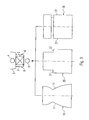
- Fig. 1 shows the principle of the present invention.
- the luminaire consists essentially of a standardized and preassembled base module and a laminating / reflector module to be fastened to the base module.
- the base module has as an essential element on an elongated support member 1, which initially includes the operating devices for the lamps. These may for example consist of electronic ballasts 2 for controlling the lamps.
- the light of the lamp is generated in the example shown on the one hand by a arranged on the underside of the support member 1 first lamp 3, which is provided for direct illumination. In order to avoid glare effects caused by the light emitted by this first lamp 3, this is associated with a grid, which is part of the laminator / reflector module described in more detail later.
- a second lamp 4 can furthermore be arranged, which is provided for indirect illumination. With the help of a second lamp 4 surrounded pot-shaped designed indirect reflector 5, the light of this lamp 4 is blasted to the ceiling of the room to be illuminated.
- the two lamps 3 and 4 are elongate gas discharge lamps, preferably fluorescent lamps, which are controlled via the electronic ballasts 2 arranged in the carrier element 1. In this case, it is possible to set the brightness of the lamps 3 and 4 individually and thus to vary the ratio of direct to indirect lighting. Instead of a single lamp can also be provided depending on the application area also to arrange on the top and / or bottom of the support member 1 more lamps.
- fasteners are arranged by means of which the support element 1 and thus ultimately the entire lamp can be attached to the ceiling of a room. Further, on both sides in the lower region of the support element 1 latching projections 6, which allow easy attachment of the laminating / reflector modules to the support element 1 by means of latching.
- the outer shape of the luminaire is determined by a laminating / reflector module, which is fastened to the carrier element 1.
- a laminating / reflector module which is fastened to the carrier element 1.
- Fig. 1 three differently shaped laminating / reflector modules 10, 20, 30 are shown, which give the lamp in each case a completely different appearance. It is essential that the side walls 11, 21, 31 of the laminating / reflector modules 10, 20, 30 are so high, in the assembled state, they completely cover the carrier element 1 as well as the second lamp 4 arranged on its upper side and the indirect reflector 5 laterally. Accordingly, only the laminating / reflector module 10, 20, 30 is visible from the outside. Since this can be made largely free in its forms, thus luminaires of very different appearance can be obtained in a simple way.
- the indirect reflector 5 is already an integral part of the standardized base module and also attached to the carrier element 1.
- the upwardly directed light output of the second lamp 4 is therefore determined independently of the shape of the laminating / reflector module 10, 20, 30 exclusively by the indirect reflector 5.
- the laminating / reflector module 10 forms in its lower area 12 surrounding the lower lamp 3 a luminous grid composed of two direct lines Reflector walls 13 and transverse thereto arranged cross blades 15.
- the transverse lamellae 15 are latched with their end regions in each case with the two direct reflector walls 13.
- the laminating / reflector module 10 shown in FIG. 2 is characterized in an advantageous manner by the integral nature of the two side regions. These consist of a single sheet metal part which has been bent to the V-shaped structure shown, so that the direct reflector walls 13 merge integrally into the side heat 11 on their undersides. Between a direct reflector wall 13 and a side wall 11, a cavity 14 is thus formed, in which engage the arranged on the end faces of the cross blades 15 mounting tabs 16.
- the fastening tabs 16 of the transverse blades 15 are not visible from the outside. Instead, the side walls 11 form a closed surface. The side walls are laterally pulled upwards in comparison to the direct reflector walls 13, so that they completely cover both the support element 1 and the indirect reflector 5 with the upper lamp 4 arranged therein laterally.
- the side walls 11 of the laminating / reflector module 10 are visible. These can now be designed accordingly to give the lamp a desired shape.
- the side walls 11 are first drawn arcuately inward and out at the top again. As a result, they form the shape of two cup-shaped reflectors attached to one another on their head sides.
- the attachment of the laminating / reflector module 10 to the carrier element 1 takes place with the aid of latching elements 17, which are arranged on the upper sides of the direct reflector walls 13 and interact with the projections 6 on the carrier element 1.
- the laminating / reflector module 10 can thus be snapped onto the carrier element 1, which also allows a simple change of the laminating / reflector module 10 in order to give the luminaire a new shape.
- the base module is covered laterally by the laminating / reflector module, so that exclusively the shape of the laminating / reflector module still determines the aesthetic impression of the luminaire.
- the region originally provided for the indirect reflector above the support element 1 can then be used, for example, as a cable space for the passage of lines.
- FIGS. 4 to 6, in which the same elements are provided with the same reference numerals, show further design options for the laminating / reflector module.
- the different laminating / reflector modules 20, 30, 40 differ only in the design of the side walls 11.
- the shape of the direct reflector walls 13 for the grid is identical. This ensures that despite the different shapes of the laminating / reflector module and the lighting properties of the lamp for direct lighting remain unchanged. Even in these embodiments, it is possible to dispense with the upper lamp for the indirect lighting, as shown in Fig. 7.
- the present invention thus opens up the possibility of giving a luminaire a new look in a simple way. Due to the modular concept with a standardized base module, which contains the operating devices for the lamps and the lamps, and the laminating / reflector module which can be fastened thereto, even the most varied forms can be made available at low cost.
Abstract
Description
Die vorliegende Erfindung betrifft eine Leuchte zur Raumbeleuchtung, deren Aussehen auf einfache Weise verändert werden kann.The present invention relates to a luminaire for room lighting, the appearance of which can be easily changed.
Leuchten zur Raumbeleuchtung sind in unterschiedlichsten Ausgestaltungen bekannt. Die DE 196 20 209 A1 der Anmelderin beschreibt beispielsweise eine Leuchte, die einen dreiecksförmig profilierten Basiskörper als Trägerelement aufweist, in dem die Betriebsgeräte zum Betreiben der Lampen angeordnet sind. Unterhalb des Basiskörpers ist eine erste Lampe angeordnet, die zur direkten Raumbeleuchtung vorgesehen ist, d.h. das von dieser Lampe abgegebene Licht trifft im wesentlichen direkt auf den zu beleuchtenden Bereich. Um Blendeffekte zu vermeiden, ist die Lampe von einem Leuchtenraster umgeben, das zwei Direkt-Reflektorwände sowie eine Vielzahl von sich quer dazu erstreckenden Querlamellen aufweist. Das Raster dient dazu, das von der Lampe abgegebene Licht auf einen vorgegebenen Winkelbereich einzuschränken.Luminaires for room lighting are known in a variety of configurations. DE 196 20 209 A1 of the Applicant describes, for example, a luminaire which has a triangular-shaped profiled base body as a carrier element in which the operating devices for operating the lamps are arranged. Below the base body, a first lamp is arranged, which is intended for direct room lighting, i. the light emitted by this lamp strikes substantially directly on the area to be illuminated. To avoid dazzling effects, the lamp is surrounded by a light grid, which has two direct reflector walls and a plurality of transversely extending transverse fins. The grid serves to limit the light emitted by the lamp to a predetermined angular range.
Zusätzlich zu der Lampe für die Direktbeleuchtung ist an der Oberseite des Basisträgers eine weitere Lampe angeordnet, welche die Decke, an der die Leuchte befestigt ist, anstrahlt und somit einer Indirektbeleuchtung des Raumes dient. In der Regel besteht die Möglichkeit, die untere Lampe für die Direktbeleuchtung und die obere Lampe für die Indirektbeleuchtung getrennt voneinander anzusteuern und damit individuell den Anteil des direkten bzw. indirekten Lichts einzustellen.In addition to the lamp for direct lighting, a further lamp is arranged on the upper side of the base support, which illuminates the ceiling to which the lamp is attached, and thus serves an indirect illumination of the room. As a rule, it is possible to separately control the lower lamp for the direct lighting and the upper lamp for the indirect lighting and thus individually adjust the proportion of direct or indirect light.
Bei dieser bekannten Leuchte können seitlich an dem Basiskörper weitere, den Gesamteindruck der Leuchte bestimmende Elemente, wie beispielsweise Flügel oder zusätzliche Indirekt-Reflektoren angeordnet werden. Grundsätzlich sind jedoch der dreiecksförmige Basiskörper bzw. seine beiden Seitenflächen von außen her sichtbar, so dass sich unabhängig von den zusätzlichen Anbauelementen der durch die Seitenflächen hervorgerufene ästhetische Eindruck nicht verändert.In this known luminaire can laterally on the base body further, the overall impression of the luminaire determining elements, such as wings or additional indirect reflectors are arranged. Basically, however, the triangular base body or its two side surfaces are visible from the outside, so that regardless of the additional attachment elements caused by the side surfaces aesthetic impression does not change.
Aus der DE 88 01 786.9 U1 ist eine Langfeldleuchte bekannt, welche zur Verwendung in Reinsträumen vorgesehen ist. Diese weist eine Gasentladungslampe auf, welche über ein Halteteil gehalten wird. An dem Halteteil ist ein Tragrahmen befestigt, welcher zwei Stirnseiten aufweist, die das Halteteil sowie die Lampenfassungen seitlich übergreifen. An diesem Tragrahmen ist ein Reflektorgehäuse befestigt, welches zum einen Reflektorinnenwände zur gerichteten Abstrahlung des von der Lampe abgegebenen Lichts sowie zum anderen Seitenwände aufweist, welche das Halteteil für die Leuchtstofflampe sowie den Tragrahmen seitlich überdecken. Die äußere Gestalt der Langfeldleuchte wird somit im wesentlichen durch die Seitenwände des Reflektorgehäuses bestimmt.From DE 88 01 786.9 U1 a linear luminaire is known, which is intended for use in clean rooms. This has a gas discharge lamp, which is held by a holding part. On the holding part, a support frame is attached, which has two end faces, which engage over the holding part and the lamp holders laterally. On this support frame, a reflector housing is attached, which has a reflector inner walls for directional radiation of the light emitted by the lamp and the other side walls which cover the holding part for the fluorescent lamp and the support frame on the one hand. The outer shape the field lamp is thus determined substantially by the side walls of the reflector housing.
Der vorliegenden Erfindung liegt die Aufgabe zugrunde, die Möglichkeit zu schaffen, einer Leuchte der vorbeschriebenen Art auf einfache Weise ein neues Aussehen zu verleihen.The present invention has for its object to provide the ability to give a luminaire of the type described above in a simple way a new look.
Die Aufgabe wird durch eine Leuchte, welche die Merkmale des Anspruchs 1 aufweist, gelöst. Die Leuchte besteht grundsätzlich gesehen aus einem Basismodul und einem sog. Kaschier-/ Reflektormodul. Das Basismodul weist ein längliches Trägerelement auf, das zumindest an seiner Unterseite Fassungen für eine zur Direktbeleuchtung vorgesehene Lampe sowie ein Betriebsgerät - wie z.B. ein elektronisches Vorschaltgerät - zum Ansteuern und Betreiben der Lampe trägt. An dem Basismodul kann das Kaschier-/ Reflektormodul befestigt werden, das Direkt-Reflektorwände für die Lampe aufweist, sowie mit diesen verbundene Seitenwände, wobei die Seitenwände nach oben verlängert sind, um das Basismodul seitlich abzudecken bzw. zu kaschieren. Die Befestigung des Kaschier-/ Reflektormoduls an dem Trägerelement des Basismoduls erfolgt dabei durch an den Oberseiten der Direkt-Reflektorwände angeordnete Rastelemente.The object is achieved by a luminaire having the features of
Gemäß der vorliegenden Erfindung wird somit der ästhetische Eindruck der Lampe ausschließlich durch die seitliche Abdeckung des Kaschier-/ Reflektormoduls bestimmt, da nach außen hin weder das Trägerelement noch das darin angeordneten Betriebsgerät für die Lampe sichtbar sind. Eine einfache Befestigung des Kaschier-/Reflektormoduls an der Leuchte erfolgt dabei durch Rastelemente, welche erfindungsgemäß derart angeordnet sind, dass sie einerseits eine einfache Montage bzw. Demontage ermöglichen und andererseits die Lichtabstrahlung nicht beeinflussen.According to the present invention, therefore, the aesthetic appearance of the lamp is determined solely by the lateral coverage of the laminating / reflector module, since to the outside neither the carrier element nor the operating device arranged therein are visible to the lamp. A simple attachment of the laminating / reflector module to the luminaire is effected by latching elements which are arranged according to the invention such that, on the one hand, they permit easy assembly and disassembly and, on the other hand, do not influence the light emission.
Bei der Endmontage der Leuchte liegen somit im wesentlichen zwei Module vor. Einerseits das Basismodul mit dem Trägerelement und dem Betriebsgerät sowie andererseits das Kaschier-/ Reflektormodul, das den ästhetischen Eindruck der Leuchte bestimmt. Die vollständige Leuchte wird dann einfach durch die Befestigung des Kaschier-/ Reflektormoduls an dem vormontierten Basismodul erhalten. Auf diese Weise ergibt sich vorteilhaft, dass unter Verwendung eines standardisierten Basismoduls unterschiedliche ästhetische Leuchtengestaltungen auf einfache Weise durch Montage von entsprechend gestalteten Kaschier-/ Reflektormodulen erzielt werden können. Erfindungsgemäß wird das Kaschier-/ Reflektormodul einfach mit dem Trägerelement verrastet, so das auf einfache und schnelle Weise ein Austausch von Kaschier-/ Reflektormodulen erfolgen und somit der Leuchte ein neues Aussehen verliehen werden kann.In the final assembly of the lamp are thus essentially two modules. On the one hand the base module with the carrier element and the operating device and on the other hand, the laminating / reflector module, which determines the aesthetic appearance of the lamp. The complete luminaire is then obtained simply by attaching the laminating / reflector module to the preassembled base module. In this way, it is advantageous that using a standardized base module different aesthetic lighting designs can be achieved in a simple manner by mounting appropriately designed laminating / reflector modules. According to the invention, the laminating / reflector module is simply locked to the carrier element, so that in a simple and fast way an exchange made of laminating / reflector modules and thus the lamp can be given a new look.
Weiterbildungen sind Gegenstand der Unteransprüche.Further developments are the subject of the dependent claims.
So weist das Trägerelement des Basismoduls vorzugsweise an seiner Oberseite weitere Fassungen für eine zur Indirektbeleuchtung vorgesehene weitere Lampe sowie ein zum Betreiben dieser weiteren Lampe erforderliches zweites Betriebsgerät auf. Um trotz allem möglichst gleichbleibende lichttechnische Eigenschaften für die Leuchte zu erzielen, ist der zweiten Lampe für die Indirektbeleuchtung dann vorzugsweise ein eigener Indirekt-Reflektor zugeordnet, der ebenfalls an dem Trägerelement befestigt ist. Die Lichtabgabe der zweiten Lampe wird dabei ausschließlich von dem Indirekt-Reflektor bestimmt, so dass unabhängig von den oft unter ästhetischen Gesichtspunkten vorgegebenen Formen des Kaschier-/ Reflektormoduls tatsächlich die Funktion eines Indirekt-Reflektors vorhanden ist. Nach wie vor ist allerdings auch dieser Indirekt-Reflektor durch die hochgezogenen Seitenwände des Kaschier-/Reflektormoduls seitlich abgedeckt und nicht sichtbar.Thus, the carrier element of the base module preferably has on its upper side further sockets for a further light intended for indirect lighting and a second operating device required for operating this further lamp. In order to achieve as constant as possible lighting properties for the luminaire, the second lamp for indirect lighting then preferably associated with a separate indirect reflector, which is also attached to the support element. The light output of the second lamp is determined exclusively by the indirect reflector, so that regardless of the often given aesthetic aspects of forms of laminating / reflector module actually the function of an indirect reflector is present. As before, however, this indirect reflector is laterally covered by the raised side walls of the laminating / reflector module and not visible.
Gemäß einer vorteilhaften Ausgestaltung der Erfindung sind die Seitenwände des Kaschier-/ Reflektormoduls integral mit den Direkt-Reflektorwänden verbunden, wodurch eine besonders kostengünstig herstellbare aber stabile Ausführungsform erhalten wird. Alternativ dazu besteht allerdings auch die Möglichkeit, die Seitenwände durch Verklemmen an den Direkt-Reflektorwänden zu befestigen. Für den Fall einer integralen Verbindung gehen die Direkt-Reflektorwände vorzugsweise an ihren Unterseiten einstückig in die Seitenwände das Kaschier-/ Reflektormoduls über, so dass dieses in seinem unteren Bereich doppelwandig ausgebildet ist. Zwischen den Direkt-Reflektorwänden erstrecken sich dann Querlamellen, die mit ihren Stirnseiten jeweils an den Direkt-Reflektorwänden befestigt, vorzugsweise mit ihnen verrastet sind. Der Vorteil dieser doppelwandigen Ausgestaltung des Kaschier-/Reflektormoduls besteht dann darin, dass dessen Seitenwände eine glatte bzw. geschlossene Oberfläche bilden, ohne das die Elemente für die Befestigung der Querlamellen an den Direkt-Reflektorwänden von außen her sichtbar sind.According to an advantageous embodiment of the invention, the side walls of the laminating / reflector module are integrally connected to the direct reflector walls, whereby a particularly inexpensive to produce but stable embodiment is obtained. Alternatively, however, it is also possible to attach the side walls by jamming to the direct reflector walls. In the case of an integral connection, the direct reflector walls preferably merge integrally into the side walls of the laminating / reflector module on their undersides so that it is double-walled in its lower region. Between the direct reflector walls then cross blades extend, which are fixed with their end faces in each case to the direct reflector walls, preferably locked with them. The advantage of this double-walled embodiment of the laminating / reflector module then consists in that its side walls form a smooth or closed surface, without which the elements for the attachment of the transverse laminations to the direct reflector walls are visible from the outside.
Die Erfindung bezieht sich auch auf ein Verfahren zur Herstellung einer Leuchte, wobei in einem ersten Schritt ein vorgefertigtes Basismodul bereitgestellt wird, das aus einem länglichen Trägerelement besteht, welches zumindest an seiner Unterseite Fassungen für eine zur Direktbeleuchtung vorgesehene Lampe sowie ein Betriebsgerät zum Ansteuern und Betreiben der Lampe trägt, und wobei zum Fertigstellen der Leuchte an dem vorgefertigten Basismodul ein Kaschier-/ Reflektormodul befestigt wird, das Direkt-Reflektorwände für die Lampe sowie mit diesen verbundene Seitenwände aufweist, wobei die Seitenwände nach oben zur seitlichen Abdeckung des Basismoduls verlängert sind. Die Befestigung des Kaschier-/ Reflektormoduls erfolgt hierbei mit Hilfe von an den Oberseiten der Direkt-Reflektorwände angeordneten Rastelementen Durch Bereitstellung mehrerer Kaschier-/ Reflektormodule mit unterschiedlichen Formen können dann auf einfache und kostengünstige Weise Leuchten mit einem jeweils unterschiedlichen ästhetischen Eindruck erhalten werden.The invention also relates to a method for producing a lamp, wherein in a first step, a prefabricated base module is provided, which consists of an elongate support member, which at least on its underside mountings for a lamp provided for direct lighting and a control gear for driving and operating the lamp carries, and attached to the completion of the lamp on the prefabricated base module a laminating / reflector module which has direct reflector walls for the lamp and sidewalls connected thereto, the sidewalls being extended upwardly to the side cover of the base module. The attachment of the laminating / reflector module takes place here by means of arranged on the upper sides of the direct reflector walls locking elements by providing multiple laminating / reflector modules with different shapes can then be obtained in a simple and inexpensive way lights with a different aesthetic impression.
Nachfolgend soll die Erfindung anhand der beiliegenden Zeichnung näher erläutert werden. Es zeigen:
- Fig. 1 das Prinzip der erfindungsgemäß aus einem standardisierten Basismodul sowie wahlweise daran befestigbaren Kaschier-/ Reflektormodulen bestehenden Leuchte;
- Fig. 2 eine Leuchte mit einem ersten Kaschier-/ Reflektormodul im Schnitt;
- Fig. 3 eine Variante der in Fig. 2 dargestellten Leuchte; und
- Fig. 4 bis 7 weitere Ausführungsformen der Leuchte mit verschiedenen Kaschier-/Reflektormodulen.
- Figure 1 shows the principle of the present invention from a standard base module and optionally attachable laminating / reflector modules existing lamp.
- FIG. 2 shows a luminaire with a first laminating / reflector module in section; FIG.
- FIG. 3 shows a variant of the luminaire shown in FIG. 2; FIG. and
- Fig. 4 to 7 further embodiments of the lamp with different laminating / reflector modules.
Fig. 1 zeigt das Prinzip der vorliegenden Erfindung. Dieses besteht darin, dass die Leuchte im Wesentlichen aus einem standardisierten und vormontierten Basismodul sowie einem an dem Basismodul zu befestigenden Kaschier-/ Reflektormodul besteht. Das Basismodul weist als wesentliches Element ein längliches Trägerelement 1 auf, das zunächst die Betriebsgeräte für die Lampen beinhaltet. Diese können beispielsweise aus elektronischen Vorschaltgeräten 2 zur Ansteuerung der Lampen bestehen. Das Licht der Leuchte wird im dargestellten Beispiel zum Einen durch eine an der Unterseite des Trägerelements 1 angeordnete erste Lampe 3 erzeugt, die zur Direktbeleuchtung vorgesehen ist. Um Blendeffekte durch das von dieser ersten Lampe 3 abgegebene Licht zu vermeiden, ist dieser ein Raster zugeordnet, der Bestandteil des später näher beschriebenen Kaschier-/ Reflektormoduls ist.Fig. 1 shows the principle of the present invention. This consists in that the luminaire consists essentially of a standardized and preassembled base module and a laminating / reflector module to be fastened to the base module. The base module has as an essential element on an
An der Oberseite des Trägerelements 1 kann weiterhin eine zweite Lampe 4 angeordnet sein, die zur Indirektbeleuchtung vorgesehen ist. Mit Hilfe eines die zweite Lampe 4 umgebenen topfförmig ausgestalteten Indirekt-Reflektors 5 wird das Licht dieser Lampe 4 an die Decke des zu beleuchtenden Raumes gestrahlt. Bei den beiden Lampen 3 und 4 handelt es sich um längliche Gasentladungslampen, vorzugsweise um Leuchtstofflampen, die über die in dem Trägerelement 1 angeordneten elektronischen Vorschaltgeräte 2 angesteuert werden. Dabei besteht die Möglichkeit, die Helligkeit der Lampen 3 und 4 jeweils individuell einzustellen und somit das Verhältnis von Direkt- zu Indirektbeleuchtung zu variieren. Anstelle einer einzelnen Lampe kann ferner je nach Anwendungsbereich auch vorgesehen sein, an der Ober- und/oder Unterseite des Trägerelements 1 mehrere Lampen anzuordnen.On the upper side of the
An dem Trägerelement 1 sind auch (nicht dargestellte) Befestigungselemente angeordnet, mittels denen das Trägerelement 1 und damit letztendlich die gesamte Leuchte an der Decke eines Raumes befestigt werden kann. Ferner befinden sich zu beiden Seiten im unteren Bereich des Trägerelements 1 Rastvorsprünge 6, welche eine einfache Befestigung der Kaschier-/ Reflektormodule an dem Trägerelement 1 mittels Verrastung ermöglichen.On the support element 1 (not shown) fasteners are arranged by means of which the
Die äußere Gestalt der Leuchte wird durch ein Kaschier-/ Reflektormodul bestimmt, das an dem Trägerelement 1 befestigt wird. In Fig. 1 sind drei unterschiedlich gestaltete Kaschier-/ Reflektormodule 10, 20, 30 dargestellt, welche der Leuchte jeweils ein vollkommen verschiedenes Aussehen verleihen. Wesentlich ist, dass die Seitenwände 11, 21, 31 der Kaschier-/ Reflektormodule 10, 20, 30 so hoch sind, dass sie im montierten Zustand das Trägerelement 1 sowie die an dessen Oberseite angeordnete zweite Lampe 4 und den Indirekt-Reflektor 5 seitlich vollkommen abdecken. Von außen ist dementsprechend ausschließlich das Kaschier-/Reflektormodul 10, 20, 30 sichtbar. Da dieses in seinen Formen weitgehend frei gestaltet werden kann, können somit auf einfache Weise Leuchten sehr unterschiedlichen Aussehens erhalten werden.The outer shape of the luminaire is determined by a laminating / reflector module, which is fastened to the
Um trotz allem möglichst gleichbleibende lichttechnische Eigenschaften zu erhalten, ist der Indirekt-Reflektor 5 bereits fester Bestandteil des standardisierten Basismoduls und ebenfalls an dem Trägerelement 1 befestigt. Die nach oben gerichtete Lichtabgabe der zweiten Lampe 4 wird daher unabhängig von der Form des Kaschier-/ Reflektormoduls 10, 20, 30 ausschließlich von dem Indirekt-Reflektor 5 bestimmt.In order to obtain as constant as possible photometric properties despite all, the
Fig. 2 zeigt die erfindungsgemäße Leuchte mit dem ersten daran befestigten Kaschier-/ Reflektormodul 10. Wie dieser Schnittdarstellung entnommen werden kann, bildet das Kaschier-/ Reflektormodul 10 in seinem unteren, die untere Lampe 3 umgebenden Bereich 12 ein Leuchtenraster, das aus zwei Direkt-Reflektorwänden 13 sowie quer dazu angeordneten Querlamellen 15 besteht. Die Querlamellen 15 sind mit ihren Stirnbereichen jeweils mit den beiden Direkt-Reflektorwänden 13 verrastet.2 shows the luminaire according to the invention with the first laminating /
Das in Fig. 2 dargestellte Kaschier-/ Reflektormodul 10 zeichnet sich in vorteilhafter Weise durch die Einstückigkeit der beiden Seitenbereiche aus. Diese bestehen aus einem einzigen Blechteil, das zu der dargestellten V-förmigen Struktur gebogen wurde, so dass die Direkt-Reflektorwänden 13 an ihren Unterseiten jeweils einstückig in die Seitenwäride 11 übergehen. Zwischen einer Direkt-Reflektorwand 13 und einer Seitenwand 11 wird somit ein Hohlraum 14 gebildet, in den die an den Stirnseiten der Querlamellen 15 angeordneten Befestigungslaschen 16 eingreifen. Durch diese doppelwandige Ausführung sind die Befestigungslaschen 16 der Querlamellen 15 von außen her nicht sichtbar. Stattdessen bilden die Seitenwände 11 eine geschlossene Oberfläche. Die Seitenwände sind dabei im Vergleich zu den Direkt-Reflektorwänden 13 seitlich weiter nach oben gezogen, so dass sie sowohl das Trägerelement 1 als auch den Indirekt-Reflektor 5 mit der darin angeordneten oberen Lampe 4 seitlich vollkommen überdecken.The laminating /
Von der Außenseite her sind somit ausschließlich die beiden Seitenwände 11 des Kaschier-/ Reflektormoduls 10 sichtbar. Diese können nun entsprechend gestaltet werden, um der Leuchte eine gewünschte Form zu verleihen. Im dargestellten Beispiel in Fig. 2 sind die Seitenwände 11 zunächst bogenförmig nach innen gezogen und im oberen Bereich wieder nach außen geführt. Hierdurch bilden sie die Form zweier an ihren Kopfseiten aneinander angesetzten topfartigen Reflektoren.From the outside, therefore, only the two
Die Befestigung des Kaschier-/ Reflektormoduls 10 an dem Trägerelement 1 erfolgt mit Hilfe von Rastelementen 17, die an den Oberseiten der Direkt-Reflektorwände 13 angeordnet sind und mit den Vorsprüngen 6 an dem Trägerelement 1 zusammenwirken. Das Kaschier-/ Reflektormodul 10 kann somit auf das Trägerelement 1 aufgeschnappt werden, was ferner auch einen einfachen Wechsel des Kaschier-/ Reflektormoduls 10 ermöglicht, um der Leuchte eine neu Form zu verleihen.The attachment of the laminating /
Wie in Fig. 3 gezeigt ist, besteht auch die Möglichkeit, auf die obere Lampe für die Indirektbeleuchtung zu verzichten und die Leuchte stattdessen direkt an einer Decke eines zu beleuchtenden Raumes zu befestigen. Auch in diesem Fall wird das Basismodul seitlich von dem Kaschier-/ Reflektormodul überdeckt, so dass nach wie vor ausschließlich die Form des Kaschier-/ Reflektormoduls den ästhetischen Eindruck der Leuchte bestimmt. Der ursprünglich für den Indirektreflektor vorgesehene Bereich oberhalb des Trägerelements 1 kann dann beispielsweise als Kabelraum zur Durchführung von Leitungen verwendet werden.As shown in Fig. 3, it is also possible to dispense with the upper lamp for the indirect lighting and attach the light instead directly to a ceiling of a room to be illuminated. In this case too, the base module is covered laterally by the laminating / reflector module, so that exclusively the shape of the laminating / reflector module still determines the aesthetic impression of the luminaire. The region originally provided for the indirect reflector above the
Die Fig. 4 - 6, bei denen gleiche Elemente mit den gleichen Bezugszeichen versehen sind, zeigen weitere Gestaltungsmöglichkeiten für das Kaschier-/ Reflektormodul. Wie den Darstellungen entnommen werden kann, unterscheiden sich die verschiedenen Kaschier-/ Reflektormodule 20, 30, 40 ausschließlich in der Gestaltung der Seitenwände 11. Die Form der Direkt-Reflektorwände 13 für das Raster hingegen ist identisch. Hierdurch ist sichergestellt, dass trotz der verschiedenen Formgebungen des Kaschier-/ Reflektormoduls auch die lichttechnischen Eigenschaften der Leuchte für die Direktbeleuchtung unverändert bleiben. Auch bei diesen Ausgestaltungen besteht die Möglichkeit auf die obere Lampe für die Indirektbeleuchtung zu verzichten, wie in Fig. 7 dargestellt ist.FIGS. 4 to 6, in which the same elements are provided with the same reference numerals, show further design options for the laminating / reflector module. As can be seen from the illustrations, the different laminating /
Die vorliegende Erfindung eröffnet somit die Möglichkeit, einer Leuchte auf einfache Weise ein neues Aussehen zu verleihen. Aufgrund des Modulkonzepts mit einem standardisierten Basismodul, welches die Betriebsgeräte für die Lampen sowie die Lampen enthält, und dem daran befestigbaren Kaschier-/ Reflektormodul können selbst unterschiedlichste Formen kostengünstig zur Verfügung gestellt werden.The present invention thus opens up the possibility of giving a luminaire a new look in a simple way. Due to the modular concept with a standardized base module, which contains the operating devices for the lamps and the lamps, and the laminating / reflector module which can be fastened thereto, even the most varied forms can be made available at low cost.
Claims (12)
- Luminaire, comprisinga) a base module, of an elongate carrier element (1) which carries at least at its underside fittings for a lamp intended for direct illumination (3) and an operating device (2) for controlling and operating the lamp (3), andb) a cover/reflector module (10, 20, 30, 40) attachable to the base module, which has direct reflector walls (13) for the lamp (3) and side walls (11, 21, 31, 41) connected with the reflector walls, wherein the side walls (11, 21, 31, 41) are extended upwardly for laterally external covering of the base module,characterized in that
at the upper side of the direct reflector walls (13) there are arranged latch elements (17) for attaching the cover/reflector module (10, 20, 30, 40) to the carrier element (1) of the base module. - Luminaire according to claim 1,
characterized in that,
the base module has fittings for a second lamp (4) intended for indirect illumination, which fittins are arranged at the upper side of the carrier element (1). - Luminaire according to claim 2,
characterized in that,
there is associated with the second lamp (4) an indirect reflector (5) arranged at the upper side of the carrier element (1), which indirect reflector is likewise laterally covered by the cover/reflector module (10, 20, 30, 40). - Luminaire according to any preceding claim,
characterized in that,
the side walls (11, 21, 31, 41) are integrally connected with the direct reflector walls (13). - Luminaire according to claim 4,
characterized in that,
the direct reflector walls (13) transition at their undersides in one piece into the side walls (11, 21, 31, 41) of the cover/reflector module (10, 20, 30, 40). - Luminaire according to claim 5,
characterized in that,
the direct reflector walls (13) are connected with one another by means of transverse lamellas (15) extending transversely to the direct reflector walls. - Luminaire according to claim 6,
characterized in that,
the transfers lamellas (15) are latched into associated recesses of the direct reflector walls (13). - Luminaire according to any preceding claim,
characterized in that,
the latch elements (17) cooperate with projections (6) provided on the carrier element (1). - Luminaire according to any preceding claim,
characterized in that,
there are arranged on the carrier element (1) attachment elements for attaching the luminaire to a ceiling. - Method for the production of a luminaire, wherein initially a pre-fabricated base module is made available, which is of an elongate carrier element (1) which carries at least at its underside fittings for a lamp (3) intended for direct illumination and an operating device (2) for control and operation of the lamp (3),
and wherein, thereafter, for completion of the luminaire, a cover/reflector module (10, 20, 30, 40) is attached to the pre-fabricated base module, which cover/reflector module has direct reflector walls (13) for the lamp (3) and side walls (11, 21, 31, 41) connected with the direct reflector walls, wherein the side walls (11, 21, 31, 41) are upwardly extended for lateral external covering of the base module,
characterized in that,
for attaching the cover/reflector module (10, 20, 30, 40) to the carrier element (1) of the base module, the cover/reflector module (10, 20, 30, 40) is latched with the carrier element (1) with the aid of latch elements (17) arranged at the upper sides of the direct reflector walls (13). - Method according to claim 10,
characterized in that,
the side walls (11, 21, 31, 41) are integrally connected with the direct reflector walls (13). - Method according to claim 10 or 11,
characterized in that,
various cover/reflector modules (10, 20, 30, 40) are made available, the side walls (11, 21, 31, 41) of which are differently shaped.
Applications Claiming Priority (3)
| Application Number | Priority Date | Filing Date | Title |
|---|---|---|---|
| DE10243134A DE10243134A1 (en) | 2002-09-17 | 2002-09-17 | Light for room lighting has cover/reflector module for attachment to base module with direct reflection walls for lamp and side walls extended upwards for external lateral coverage of base module |
| DE10243134 | 2002-09-17 | ||
| PCT/EP2003/010292 WO2004027317A1 (en) | 2002-09-17 | 2003-09-16 | Luminaire comprising a cover/reflector module |
Publications (2)
| Publication Number | Publication Date |
|---|---|
| EP1540245A1 EP1540245A1 (en) | 2005-06-15 |
| EP1540245B1 true EP1540245B1 (en) | 2006-07-05 |
Family
ID=31896109
Family Applications (1)
| Application Number | Title | Priority Date | Filing Date |
|---|---|---|---|
| EP03748040A Expired - Lifetime EP1540245B1 (en) | 2002-09-17 | 2003-09-16 | Luminaire comprising a cover/reflector module |
Country Status (4)
| Country | Link |
|---|---|
| EP (1) | EP1540245B1 (en) |
| AT (1) | ATE332478T1 (en) |
| DE (2) | DE10243134A1 (en) |
| WO (1) | WO2004027317A1 (en) |
Families Citing this family (2)
| Publication number | Priority date | Publication date | Assignee | Title |
|---|---|---|---|---|
| DE102004018382A1 (en) * | 2004-04-16 | 2005-11-17 | Trilux-Lenze Gmbh + Co Kg | lamp |
| DE202008003097U1 (en) | 2008-03-05 | 2009-08-06 | Zumtobel Lighting Gmbh | Lighting arrangement with support profile |
Family Cites Families (5)
| Publication number | Priority date | Publication date | Assignee | Title |
|---|---|---|---|---|
| DE3216442A1 (en) * | 1982-05-03 | 1983-11-03 | Jürgen Brickl | Reflector for producing freedom from glare in elongated lighting fittings, in particular ceiling light fittings |
| DE8801786U1 (en) * | 1988-02-11 | 1988-03-31 | Siemens Ag, 1000 Berlin Und 8000 Muenchen, De | |
| DE19620209A1 (en) * | 1996-05-20 | 1997-11-27 | Zumtobel Licht | Luminaire with a profiled base body as a support for at least one lamp |
| DE29806967U1 (en) * | 1998-04-19 | 1998-06-10 | Trilux Lenze Gmbh & Co Kg | Trunking system |
| DE20106296U1 (en) * | 2001-04-10 | 2001-09-13 | Drews Hartmuth | Terminal base reflector |
-
2002
- 2002-09-17 DE DE10243134A patent/DE10243134A1/en not_active Withdrawn
-
2003
- 2003-09-16 WO PCT/EP2003/010292 patent/WO2004027317A1/en active IP Right Grant
- 2003-09-16 AT AT03748040T patent/ATE332478T1/en active
- 2003-09-16 DE DE50304157T patent/DE50304157D1/en not_active Expired - Lifetime
- 2003-09-16 EP EP03748040A patent/EP1540245B1/en not_active Expired - Lifetime
Also Published As
| Publication number | Publication date |
|---|---|
| WO2004027317A1 (en) | 2004-04-01 |
| ATE332478T1 (en) | 2006-07-15 |
| DE50304157D1 (en) | 2006-08-17 |
| DE10243134A1 (en) | 2004-03-25 |
| EP1540245A1 (en) | 2005-06-15 |
Similar Documents
| Publication | Publication Date | Title |
|---|---|---|
| EP1438532B1 (en) | Lighting device comprising a plurality of pot reflectors | |
| EP1688662B1 (en) | Luminaire | |
| EP2151899B1 (en) | Light strip system | |
| EP3293441A1 (en) | Luminaire | |
| DE202009016793U1 (en) | Arrangement for emitting light | |
| EP0897511B1 (en) | Light fixture with a linear lighting field, suitable for forming lighting trunking | |
| EP3270047A2 (en) | Flat light | |
| EP2507543A1 (en) | Wall and/or ceiling system for illumination | |
| EP1540245B1 (en) | Luminaire comprising a cover/reflector module | |
| EP1650495B1 (en) | Corner lamp | |
| DE10321282B4 (en) | wall light | |
| EP1616124B1 (en) | Louvered luminaire | |
| DE19721340A1 (en) | Lamp fitting for at least one artificial light source, e.g. fluorescent tube | |
| EP2176583B1 (en) | Light with a grid for light output | |
| WO2013102640A1 (en) | Luminaire element and luminaire | |
| EP1279889A1 (en) | Light with base unit and tub-shaped cover and a base unit for the lamp | |
| DE102020208809B4 (en) | Lighting arrangement with a tubular lighting device | |
| DE202007013177U1 (en) | lamp | |
| EP3446031A1 (en) | Switchgear cabinet lighting unit having an adjustable lighting means board | |
| EP1258675B1 (en) | Illumination device with adjustable light cone | |
| EP1519103B1 (en) | Lamp with an elongated gas discharge lamp | |
| WO2009052939A1 (en) | High-bay reflector luminaire | |
| EP3138369B1 (en) | Method for operating a light having a plurality of lighting units which are arranged behind each other | |
| DE102018133311A1 (en) | Luminaire housing and luminaire | |
| DE102004039676A1 (en) | grid array |
Legal Events
| Date | Code | Title | Description |
|---|---|---|---|
| PUAI | Public reference made under article 153(3) epc to a published international application that has entered the european phase |
Free format text: ORIGINAL CODE: 0009012 |
|
| 17P | Request for examination filed |
Effective date: 20050202 |
|
| AK | Designated contracting states |
Kind code of ref document: A1 Designated state(s): AT BE BG CH CY CZ DE DK EE ES FI FR GB GR HU IE IT LI LU MC NL PT RO SE SI SK TR |
|
| RBV | Designated contracting states (corrected) |
Designated state(s): AT CH DE LI |
|
| GRAP | Despatch of communication of intention to grant a patent |
Free format text: ORIGINAL CODE: EPIDOSNIGR1 |
|
| GRAS | Grant fee paid |
Free format text: ORIGINAL CODE: EPIDOSNIGR3 |
|
| GRAA | (expected) grant |
Free format text: ORIGINAL CODE: 0009210 |
|
| RAP1 | Party data changed (applicant data changed or rights of an application transferred) |
Owner name: ZUMTOBEL LIGHTING GMBH |
|
| AK | Designated contracting states |
Kind code of ref document: B1 Designated state(s): AT CH DE LI |
|
| REG | Reference to a national code |
Ref country code: CH Ref legal event code: EP |
|
| REG | Reference to a national code |
Ref country code: CH Ref legal event code: NV Representative=s name: A. BRAUN, BRAUN, HERITIER, ESCHMANN AG PATENTANWAE |
|
| REF | Corresponds to: |
Ref document number: 50304157 Country of ref document: DE Date of ref document: 20060817 Kind code of ref document: P |
|
| PLBE | No opposition filed within time limit |
Free format text: ORIGINAL CODE: 0009261 |
|
| STAA | Information on the status of an ep patent application or granted ep patent |
Free format text: STATUS: NO OPPOSITION FILED WITHIN TIME LIMIT |
|
| 26N | No opposition filed |
Effective date: 20070410 |
|
| REG | Reference to a national code |
Ref country code: CH Ref legal event code: PFA Owner name: ZUMTOBEL LIGHTING GMBH Free format text: ZUMTOBEL LIGHTING GMBH#SCHWEIZER STRASSE 30#6850 DORNBIRN (AT) -TRANSFER TO- ZUMTOBEL LIGHTING GMBH#SCHWEIZER STRASSE 30#6850 DORNBIRN (AT) |
|
| PGFP | Annual fee paid to national office [announced via postgrant information from national office to epo] |
Ref country code: DE Payment date: 20101129 Year of fee payment: 8 |
|
| PGFP | Annual fee paid to national office [announced via postgrant information from national office to epo] |
Ref country code: CH Payment date: 20110929 Year of fee payment: 9 |
|
| PGFP | Annual fee paid to national office [announced via postgrant information from national office to epo] |
Ref country code: AT Payment date: 20110929 Year of fee payment: 9 |
|
| REG | Reference to a national code |
Ref country code: CH Ref legal event code: PL |
|
| REG | Reference to a national code |
Ref country code: AT Ref legal event code: MM01 Ref document number: 332478 Country of ref document: AT Kind code of ref document: T Effective date: 20120916 |
|
| PG25 | Lapsed in a contracting state [announced via postgrant information from national office to epo] |
Ref country code: LI Free format text: LAPSE BECAUSE OF NON-PAYMENT OF DUE FEES Effective date: 20120930 Ref country code: AT Free format text: LAPSE BECAUSE OF NON-PAYMENT OF DUE FEES Effective date: 20120916 Ref country code: CH Free format text: LAPSE BECAUSE OF NON-PAYMENT OF DUE FEES Effective date: 20120930 Ref country code: DE Free format text: LAPSE BECAUSE OF NON-PAYMENT OF DUE FEES Effective date: 20130403 |
|
| REG | Reference to a national code |
Ref country code: DE Ref legal event code: R119 Ref document number: 50304157 Country of ref document: DE Effective date: 20130403 |