EP1615785B1 - Outil pour systemes de telesurveillance - Google Patents
Outil pour systemes de telesurveillance Download PDFInfo
- Publication number
- EP1615785B1 EP1615785B1 EP04760072A EP04760072A EP1615785B1 EP 1615785 B1 EP1615785 B1 EP 1615785B1 EP 04760072 A EP04760072 A EP 04760072A EP 04760072 A EP04760072 A EP 04760072A EP 1615785 B1 EP1615785 B1 EP 1615785B1
- Authority
- EP
- European Patent Office
- Prior art keywords
- tire
- tool
- signals
- receiving
- signal
- Prior art date
- Legal status (The legal status is an assumption and is not a legal conclusion. Google has not performed a legal analysis and makes no representation as to the accuracy of the status listed.)
- Expired - Lifetime
Links
- 238000012544 monitoring process Methods 0.000 title claims description 29
- 230000003213 activating effect Effects 0.000 claims description 40
- 230000004913 activation Effects 0.000 claims description 18
- 238000000034 method Methods 0.000 claims description 16
- 238000004519 manufacturing process Methods 0.000 description 6
- 230000008859 change Effects 0.000 description 3
- 230000000881 depressing effect Effects 0.000 description 2
- 238000010586 diagram Methods 0.000 description 2
- 238000003825 pressing Methods 0.000 description 2
- 230000004044 response Effects 0.000 description 2
- 230000009471 action Effects 0.000 description 1
- 238000013459 approach Methods 0.000 description 1
- 230000008901 benefit Effects 0.000 description 1
- 238000004891 communication Methods 0.000 description 1
- 238000004590 computer program Methods 0.000 description 1
- 230000001419 dependent effect Effects 0.000 description 1
- 238000009434 installation Methods 0.000 description 1
Images


Classifications
-
- B—PERFORMING OPERATIONS; TRANSPORTING
- B60—VEHICLES IN GENERAL
- B60C—VEHICLE TYRES; TYRE INFLATION; TYRE CHANGING; CONNECTING VALVES TO INFLATABLE ELASTIC BODIES IN GENERAL; DEVICES OR ARRANGEMENTS RELATED TO TYRES
- B60C23/00—Devices for measuring, signalling, controlling, or distributing tyre pressure or temperature, specially adapted for mounting on vehicles; Arrangement of tyre inflating devices on vehicles, e.g. of pumps or of tanks; Tyre cooling arrangements
- B60C23/02—Signalling devices actuated by tyre pressure
- B60C23/04—Signalling devices actuated by tyre pressure mounted on the wheel or tyre
- B60C23/0408—Signalling devices actuated by tyre pressure mounted on the wheel or tyre transmitting the signals by non-mechanical means from the wheel or tyre to a vehicle body mounted receiver
- B60C23/0422—Signalling devices actuated by tyre pressure mounted on the wheel or tyre transmitting the signals by non-mechanical means from the wheel or tyre to a vehicle body mounted receiver characterised by the type of signal transmission means
- B60C23/0433—Radio signals
-
- B—PERFORMING OPERATIONS; TRANSPORTING
- B60—VEHICLES IN GENERAL
- B60C—VEHICLE TYRES; TYRE INFLATION; TYRE CHANGING; CONNECTING VALVES TO INFLATABLE ELASTIC BODIES IN GENERAL; DEVICES OR ARRANGEMENTS RELATED TO TYRES
- B60C23/00—Devices for measuring, signalling, controlling, or distributing tyre pressure or temperature, specially adapted for mounting on vehicles; Arrangement of tyre inflating devices on vehicles, e.g. of pumps or of tanks; Tyre cooling arrangements
- B60C23/02—Signalling devices actuated by tyre pressure
- B60C23/04—Signalling devices actuated by tyre pressure mounted on the wheel or tyre
- B60C23/0408—Signalling devices actuated by tyre pressure mounted on the wheel or tyre transmitting the signals by non-mechanical means from the wheel or tyre to a vehicle body mounted receiver
- B60C23/0471—System initialisation, e.g. upload or calibration of operating parameters
-
- B—PERFORMING OPERATIONS; TRANSPORTING
- B60—VEHICLES IN GENERAL
- B60C—VEHICLE TYRES; TYRE INFLATION; TYRE CHANGING; CONNECTING VALVES TO INFLATABLE ELASTIC BODIES IN GENERAL; DEVICES OR ARRANGEMENTS RELATED TO TYRES
- B60C23/00—Devices for measuring, signalling, controlling, or distributing tyre pressure or temperature, specially adapted for mounting on vehicles; Arrangement of tyre inflating devices on vehicles, e.g. of pumps or of tanks; Tyre cooling arrangements
- B60C23/02—Signalling devices actuated by tyre pressure
- B60C23/04—Signalling devices actuated by tyre pressure mounted on the wheel or tyre
- B60C23/0408—Signalling devices actuated by tyre pressure mounted on the wheel or tyre transmitting the signals by non-mechanical means from the wheel or tyre to a vehicle body mounted receiver
- B60C23/0479—Communicating with external units being not part of the vehicle, e.g. tools for diagnostic, mobile phones, electronic keys or service stations
Definitions
- the present invention relates to apparatus and methods useful for communicating with remote tire monitoring systems. More specifically, the present invention provides apparatus and methods that are capable of communicating with different remote tire monitoring systems made by different manufacturers.
- RTMSs Remote tire monitoring systems
- Such systems typically include a plurality of sensor units or transmitters associated with the tires of a vehicle (“tire sensors”), such as an automobile, truck, or other wheeled vehicle, along with a receiving unit.
- the sensors measure a tire characteristic, most commonly the air pressure in the associated tire, and communicate data corresponding to the tire characteristic to the receiving unit on the vehicle.
- the data is typically communicated to the receiving unit via radio frequency (“RF") signals.
- RF signals can be modulated and encoded to transmit data such as tire pressure, unique identifier, etc.
- the receiver typically takes some action in response to receiving the transmitted data, such as providing an alarm or providing a display to the operator of the vehicle indicative of the tire characteristic.
- the RTMS tire sensor detects the low air pressure and signals to the RTMS receiving unit, which then indicates to the operator of the vehicle which tire has the low air pressure.
- the receiver In order for the receiver to reliably indicate the tire characteristic to the vehicle operator, the receiver preferably associates the tire sensor (and therefore, the tire characteristic data) with a tire position on the vehicle. This association is made upon initial installation of tires on the vehicle and must be repeated each time tire positions are changed, such as after tire rotation, or a new tire is installed.
- a technician installing new tires on a vehicle or changing the positions of tires (that is, rotating tires) on a vehicle can program the vehicle's RTMS receiving unit to associate the tires on the vehicle with their tire positions by first putting the receiving unit into learn mode or programming mode and then activating the tire sensors in a sequence specified by the manufacturer of the RTMS receiving unit.
- the methods for putting receiving units into programming mode are typically manufacturer dependent, but are generally known in the art. For example, it is known in the art that some RTMS receiving units manufactured by Ford Motor Company can be put into programming mode by first turning the ignition on (not in start position) and off three times, followed by depressing the vehicle's brake, followed by again turning the ignition on and off three times.
- the receiving unit Once the receiving unit is placed into programming mode it will expect the tire sensors to be activated in a particular sequence. That is, the receiving unit may expect the tire sensor in the right front tire to be activated first, followed by the tire sensor in the left front tire, etc.
- the precise sequence for activating tire sensors is determined by and readily available from the manufacturer of the RTMS.
- each tire sensor As each tire sensor is activated, it transmits a signal ("tire sensor signal") to the receiving unit.
- the tire sensor signal will typically contain a unique ID that identifies the particular tire (that is, tire sensor) that is transmitting the tire sensor signal.
- the receiving unit associates this unique ID with the position of the tire from which the signal is being transmitted. In this manner, the receiving unit learns the position of each tire as it is being activated.
- the receiving unit will typically emit a sound, such as a beeping sound, to indicate to the technician that the receiving unit received a tire sensor signal from the activated tire and that the next tire in the sequence can be then activated.
- a tire sensor transmits its unique ID along with pertinent data about the tire (such as tire pressure, for example) and the receiving unit can then display the transmitted data as necessary to the operator of the vehicle, also indicating the tire position to the operator. For example, if while a vehicle is in operation the right front tire starts losing air pressure, the loss of air pressure is detected by the tire sensor in the right front tire, the tire sensor transmits the tire pressure to the receiving unit (along with its unique ID), the receiving unit determines the tire position (that is, right front) of the transmitting tire sensor from the previous association of unique ID to tire position and then indicates to the operator of the vehicle that the right front tire has low tire pressure.
- pertinent data about the tire such as tire pressure, for example
- US 2002/130771 describes a system for remotely sensing the temperature and pressure in vehicle tires whether moving or stationary.
- the tire pressure and temperature data along with a unique ID number are transmitted from a sensor in the tire to a computer display in the cab.
- a portable cab display receives the data and assigns a unique wheel location for each sensor.
- the cab display compensates the pressure data for local barometric pressure and actual tire temperature and displays the compensated data to the driver. Alarms are included to alert the driver of off specification conditions.
- the cab display may be removed from the cab for local use.
- EP 1026015 describes a tire characteristic monitoring method for automatic programming of tire position information in a remote tire pressure monitoring system.
- the method includes, from a remotely located exciter using a primary coil to transmit a relatively low frequency signal to a secondary coil of a tire monitor associated with a tire of a vehicle.
- the method further includes the step of, at the tire monitor, in response to the relatively low frequency signal, transmitting a relatively high transmitting signal to convey data.
- the data are received at the exciter and subsequently loaded into a receiving unit of the vehicle.
- Remote tire monitoring systems are produced by a plurality of manufacturers.
- RTMS tire sensors designed by different manufacturers typically utilize different methods for activating the tire sensors.
- one RTMS manufacturer may build its tire sensors such that they are activated by a magnetic field that can be generated by a magnet.
- a second way that some tire sensors can be activated is by a change in air pressure in the tire.
- a third way that some tire sensors can be activated is by the rotation of the tire.
- a fourth way that some tire sensors can be activated is by temperature.
- RTMS manufacturers may also build tire sensors such that they are activated by a continuous wave low frequency (“LF") or radio frequency (“RF”) signal.
- LF continuous wave low frequency
- RF radio frequency
- Still other RTMS manufacturers may build tire sensors such that they are activated by a modulated low frequency (“LF”) or radio frequency (“RF”) signal.
- different manufacturers frequently utilize different methods for transmitting data from the tire sensor (upon activation) to the receiving unit. For example, one manufacturer may build tire sensors such that they transmit, and the receiving units receive, data via a RF signal at a particular frequency, such as 315 MHz. A second manufacturer may build tire sensors such that they transmit data via a RF signal at a different frequency, such as 433 MHz. A third manufacture may build tire sensors such that they transmit data via a RF signal at yet another frequency, such as 916 MHz.
- the present invention provides for a tire positioning tool that can be utilized to work with remote tire monitoring systems made by different manufacturers.
- Tire positioning tools of the present invention are capable of activating RTMS tire sensors using one of a plurality of means.
- Preferred tire positioning tools of the present invention are capable of receiving signals of a plurality of frequencies transmitted by activated RTMS tire sensors.
- Preferred tire positioning tools of the present invention are also capable of transmitting data to a RTMS receiving unit and/or receiving data from a RTMS receiving unit using one of a plurality of signal frequencies. In this manner, a technician tasked to install a new tire or to rotate tires can utilize a single tool to work with remote tire monitoring systems made by different manufacturers.
- tire positioning tools of the present invention comprise a plurality of means for activating tire sensors and are thus capable of activating a plurality of makes of RTMS tire sensors.
- tire positioning tools of the present invention additionally comprise signal receiving circuitry capable of receiving data transmitted from a plurality of makes of activated RTMS tire sensors.
- tire positioning tools of the present invention comprise signal transmitting circuitry capable of transmitting data to a plurality of different makes of RTMS receiving units.
- tire positioning tools of the present invention additionally comprise signal receiving circuitry capable of receiving data transmitted from a plurality of makes of activated RTMS receiving units.
- Remote tire monitoring systems are produced by a plurality of manufacturers.
- RTMS tire sensors designed by different manufacturers typically utilize different methods for activating the tire sensors.
- one manufacturer may build its tire sensors such that they are activated by a magnetic field that can be generated by a magnet.
- the tire sensor will activate.
- a second way that some tire sensors can be activated is by a change in air pressure in the tire. That is, if the air pressure changes by a certain amount (typically about 5 psi) then the tire sensor activates.
- a third way that some tire sensors can be activated is by the rotation of the tire.
- Radio frequency signals having a frequency of less than about 30 MHz are typically referred to as low frequency (“LF") signals and signals having a frequency greater than about 30 MHz are typically referred to as radio frequency (“RF”) signals. Accordingly, radio frequency signals having a frequency of less than or equal to 30 MHz are referred to herein as LF signals and radio frequency signals having a frequency of greater than 30 MHz are referred to herein as RF signals.
- LF low frequency
- RF radio frequency
- a fifth way that some tire sensors may be activated is by a continuous wave LF signal or a continuous wave RF signal.
- these tire sensors will activate whenever they receive a continuous wave signal for a certain period of time (commonly, at least 6 seconds).
- Another RTMS manufacturer may build its tire sensors such that they are activated by a modulated LF or modulated RF signal.
- a LF or RF signal transmitted for the purpose of activating a RTMS tire sensor, whether continuous or modulated, is referred to herein as an activation signal.
- Tire positioning tools of the present invention will comprise a plurality of means for activating tire sensors.
- Tire positioning tools of the present invention can be manufactured utilizing as few as two different means for activating tire sensors. Producing tire positioning tools of the present invention having as few as two different means for activating tire sensors may be useful, for example, if it is known that the tire positioning tool will only be used in circumstances requiring the tool to be used in conjunction with as few as two different known makes of RTMS.
- Tire positioning tools of the present invention having fewer different means for activating tire sensors will generally be less expensive to manufacture than tire positioning tools of the present invention having many different means for activating tire sensors.
- a tire positioning tool according to the present invention can be manufactured with many different means for activating tire sensors.
- tire positioning tools of the present invention can have a magnet attached to the tire positioning tool, typically being placed inside the tool.
- Some tire sensors are manufactured such that when the tire sensor is placed within a magnetic field as is generated by a magnet, the sensor becomes activated.
- a tire positioning tool containing a magnet will need to be positioned within a few inches of the tire sensor before the tire sensor is activated by the magnet.
- the types of magnets useful for activating tire sensors are known in the art and an appropriate magnet for inclusion in tire positioning tools of the present invention can be readily determined by one of ordinary skill in the art.
- a technician When a technician is working with a remote tire monitoring system comprising tire sensors that are activated by a magnet, a technician can first put the RTMS receiving unit into programming mode and then use a tire positioning tool of the present invention on each tire in the appropriate sequence to activate the tire sensor by placing the tire positioning tool sufficiently close to the tire to put the tire sensor within the magnetic field of the magnet.
- a second means for activating tire sensors that can be incorporated into tire positioning tools of the present invention involves the use of a valve core depressor. It is well known in the art to lower a tire's air pressure by depressing the valve core and letting air out of the tire. There are tools known in the art that are used to depress valve cores and let air out of a tire. These tools are referred to herein as valve core depressors.
- Tire positioning tools of the present invention can have a valve core depressor attached to or built into the casing of the tool making it easy for a technician to lower the air pressure in a tire.
- a technician When a technician is working with a remote tire monitoring system comprising tire sensors that are activated by a change in tire pressure, a technician can first put the RTMS receiving unit into programming mode and then use a tire positioning tool of the present invention on each tire in the appropriate sequence to let out an amount of air sufficient to reduce the tire pressure enough to activate the tire sensor.
- a third means for activating tire sensors that can be incorporated into tire positioning tools of the present invention involves the use of a continuous wave ("CW") LF or RF signal.
- CW continuous wave
- Some tire sensors may be manufactured such that they are activated upon receiving a CW signal of a particular frequency.
- Means for generating CW signals at a specific frequency are known in the art and any means known in the art can be utilized for generating a CW signal in tire positioning tools of the present invention.
- One means for producing a CW signal in tire positioning tools of the present invention is to include frequency generating circuitry to generate the CW signal and then amplify the CW signal with an amplifier or a driver circuit. Frequency generating circuitry as well as amplifiers and driver circuitry are known in the art and can readily be incorporated into tire positioning tools of the present invention by one of ordinary skill in the art.
- Tire positioning tools of the present invention may comprise frequency generating circuitry capable of generating a single frequency or may comprise frequency generating circuitry capable of generating a plurality of different frequencies. Different makes of RTMS tire sensors may require different frequencies of CW signal to be activated. Thus, each different frequency of CW signal generated constitutes a different means for activating RTMS tire sensors. If a tire positioning tool of the present invention is capable of generating a CW signal of only one frequency, then the tool will also comprise at least one other means of activating a RTMS tire sensor, such as a magnet. Most commonly, tire positioning tools of the present invention will comprise frequency generating circuitry capable of generating a plurality of different frequencies.
- the frequencies of the CW signals are chosen from frequencies that are known to activate different makes of RTMS tire sensors.
- Useful signals for CW signals in tire positioning tools of the present invention may include, for example, 125 KHz, 13.56 MHz, 928 MHz, and 2.4 GHz.
- a fourth means for activating tire sensors that can be incorporated into tire positioning tools of the present invention involves the use of a modulated signal.
- Some tire sensors may be manufactured such that they are activated upon receiving a modulated signal of a particular frequency.
- Means for generating modulated signals at a specific frequency are known in the art and any means known in the art can be utilized for generating a modulated signal in tire positioning tools of the present invention.
- One means for producing a modulated signal in tire positioning tools of the present invention is to include a microprocessor in addition to frequency generating circuitry. As is known in the art, the microprocessor can provide the modulation to the frequency generator circuitry. An amplifier or driver circuit can also be included to amplify the signal.
- tire positioning tools of the present invention may be capable of generating a modulated signal at only a single frequency or may be capable of generating a modulated signal at one of a plurality of frequencies. Different makes of RTMS tire sensors may require different frequencies of modulated signal to be activated. Thus, each different frequency of modulated signal generated constitutes a different means for activating RTMS tire sensors. If a tire positioning tool of the present invention is capable of generating a modulated signal at only one frequency, then the tool will also comprise at least one other means of activating a RTMS tire sensor, such as a magnet or a means for transmitting a CW signal.
- tire positioning tools of the present invention will comprise a microprocessor and frequency generating circuitry capable of generating modulated signals at a plurality of different frequencies.
- the frequencies of the modulated signals are chosen from frequencies that are known to activate different makes of RTMS tire sensors.
- Useful frequencies for modulated signals in tire positioning tools of the present invention may include, for example, 125 KHz, 13.56 MHz, 928 MHz, and 2.4 GHz.
- tire positioning tools of the present invention comprise a plurality of means for activating RTMS tire sensors.
- the plurality of means for activating RTMS tire sensors may be any combination of the means discussed above.
- tire positioning tools of the present invention may only include means for generating CW signals at two or more different frequencies and not include any other means for activating RTMS tire sensors.
- tire positioning tools of the present invention may only include means for generating modulated signals at two or more different frequencies and not include any other means for activating RTMS tire sensors.
- tire positioning tools or the present invention may include means for generating a CW signal at only one specific frequency and also include means for generating a modulated signal at only one specific frequency.
- tire positioning tools of the present invention will comprise a magnet, a core valve depressor, means for generating CW signals at two or more different frequencies, and means for generating modulated signals at two or more different frequencies.
- One advantage of utilizing a plurality of means for activating RTMS tire sensors is that a technician can utilize a single tire positioning tool of the present invention to activate a plurality of makes of RTMS tires sensors. This can be done regardless of whether the technician is aware of the specific make of the RTMS tire sensor. Once a RMTS receiving unit has been put into programming mode, a technician can use a tire positioning tool of the present invention to activate the tire sensors in the appropriate order to indicate the position of each tire to the receiving unit.
- Tire positioning tools of the present invention can be advantageously utilized for indicating tire position to a RTMS receiving unit.
- a technician utilizing a tire positioning tool of the present invention will first put the RTMS receiving unit into programming mode. Then the technician will use the tool to activate each tire sensor in the sequence expected by the receiving unit.
- the technician will use that means to activate each tire. For example, if the technician knows that a CW signal at a particular frequency will activate the tire sensors, the technician approaches each tire in the appropriate sequence, places the tire positioning tool sufficiently close to the tire such that the tire sensor is within range for receiving a CW signal from the tire positioning tool, and then activates the tire position tool in such a manner that is generates a CW signal at the particular frequency desired.
- the RTMS receiving unit indicates that a tire sensor signal has been received, the technician proceeds to the next tire in the sequence and activates its tire sensor. The technician similarly activates each tire sensor in the sequence until all tire sensors have been activated.
- the technician can proceed to the first tire after putting the RTMS receiving unit into programming mode and try to activate the tire sensor using different means until the receiving unit indicates that it has received a tire sensor signal. For example, the technician may first attempt to activate the tire sensor by placing the tire sensor within the magnetic field of the tool's magnet. If the tire sensor does not activate (that is, the receiving unit does not indicate that a tire sensor signal has been received), the technician can attempt to activate the tire sensor by having the tool generate a CW signal at a particular frequency. If the tire sensor still does not activate, the technician can attempt to activate the tire sensor by having the tool generate a CW signal at a different frequency or generate a modulated signal at a particular frequency.
- Preferred embodiments of tire positioning tools of the present invention will also comprise means for receiving signals transmitted by activated RTMS tire sensors. Once a RTMS tire sensor has been activated, the tire sensor transmits data to the receiving unit via a LF or RF signal at a particular frequency (that is, a tire sensor signal). Preferred tire positioning tools of the present invention can also receive tire sensor signals. Preferred tire positioning tools of the present invention will comprise an antenna connected to receiving circuitry capable of receiving tire sensor signals. The receiving circuitry may comprise a single receiver capable of receiving a single frequency, a single receiver capable of receiving a plurality of frequencies, or multiple receivers each of which is capable of receiving a single frequency. Preferred tire positioning tools of the present invention will additionally comprise a microprocessor for decoding tire sensors signals.
- RTMS tire sensors may transmit different frequencies of tire sensor signal.
- each different frequency of tire sensor signal that tire positioning tools of the present invention are capable of receiving constitutes a different means for receiving tire sensor signals. That is, if a tire positioning tool of the present invention comprises means for receiving tire sensor signals at a plurality of frequencies then the tire position tool comprises a plurality of means for receiving tire sensor signals.
- preferred tire positioning tools will be capable of receiving a plurality of frequencies of tire sensor signals. This can be accomplished by including a plurality of receivers into tire positioning tools of the present invention, wherein each receiver is designed to receive a signal of a particular frequency. Alternately, this can be accomplished by including a single receiver capable of receiving multiple different frequencies. For each frequency of signal known to be transmitted by a RTMS tire sensor, receiving circuitry can be included into tire position tools of the present invention such that the tire position tool can receive and decode the tire sensor signal at that frequency. Frequencies of RTMS tire sensor signals useful for tire positioning tools of the present invention to receive may include, for example, 125 KHz, 13.56 MHz, 315 MHz, 433 MHz, 848 MHz, 916 MHz, and 2.4 GHz.
- Whether to include a single receiver capable of receiving a plurality of frequencies or whether to include a plurality of receiver each of which is capable of receiving a single frequency is more of an economic decision than a technical one.
- Receivers capable of receiving a plurality of frequencies are generally more expensive to manufacture than receivers capable of receiving a single frequency. If the tire positioning tool is designed to receive only a few different frequencies, it may be more economical to include multiple receivers each receiving a single frequency. However, if the tire positioning tool is designed to receive many different frequencies, then it may be more economical to include a single receiver capable of receiving all the targeted frequencies.
- tire positioning tools of the present invention are capable of receiving can be adapted to the particular environment in which the tool will be used by a technician.
- Tire positioning tools capable of receiving a larger number of different frequencies may be used in conjunction with a larger number of makes of remote tire monitoring systems, but tire positioning tools capable of receiving fewer different frequencies will typically be less expensive to manufacture.
- RTMS tire sensor signals received by tire positioning tools of the present invention transmit data to the tire positioning tool that can be advantageously displayed.
- tire sensors may transmit, via tire sensor signals, data such as unique ID, tire pressure, tire temperature, etc.
- Preferred tire positioning tools of the present invention will include a display apparatus that can be advantageously utilized to display the transmitted data in a manner making it readable to the technician utilizing the tire positioning tool.
- Display apparatus that can be advantageously incorporated into tire positioning tools of the present invention are known in the art and may include, for example, LED devices, LCD devices, VF devices, or other devices.
- Tire positioning tools of the present invention capable of receiving tire sensor signals can be advantageously utilized by a technician in a variety of ways. For example, if a technician simply wants to determine if the tire sensor of a tire is operational, the technician can utilize the tool to activate the tire sensor. If the tire sensor's data (that is, unique ID, tire pressure, etc.) is displayed, the technician knows the tire sensor is operational. A technician may also use tire positioning tools of the present invention to check the air pressure in each of the tires to ensure that the pressure in each tire is at an adequate level. When a technician balances a tire, the technician places the tire on a device that rotates the tire. This rotation may activate the tire sensor, allowing the technician to receive the tire sensor's data while the tire is rotating. Of course, the technician can also use the tool to activate a tire while it is rotating.
- tire sensor's data that is, unique ID, tire pressure, etc.
- Preferred embodiments of tire positioning tools of the present invention will additionally comprise means for transmitting signals to RTMS receiving units. Such means will typically comprise an antenna connected to transmitting circuitry for transmitting signals and a microprocessor for encoding signals.
- the transmitting circuitry may comprise a single transmitter capable of transmitting a single frequency, a single transmitter capable of transmitting a plurality of frequencies, or multiple transmitters each of which is capable of transmitting a single frequency.
- Preferred tire positioning tools of the present invention will additionally comprise a microprocessor for signals transmitted to receiving units. Antennas, transmitting circuitry, and microprocessors useful in the present invention are known in the art and can be readily incorporated into tire positioning tools of the present invention by one of ordinary skill in the art.
- each different frequency of signal that tire positioning tools of the present invention are capable of transmitting constitutes a different means for transmitting signals. That is, if a tire positioning tool of the present invention comprises means for transmitting signals at a plurality of frequencies then the tire position tool comprises a plurality of means for transmitting signals.
- preferred tire positioning tools will be capable of transmitting a plurality of frequencies of signals to receiving units. This can be accomplished by including a plurality of transmitters into tire positioning tools of the present invention, wherein each transmitter is designed to transmit a signal of a particular frequency. Alternately, this can be accomplished by including a single transmitter capable of transmitting multiple different frequencies. For each frequency of signal known to be received by a RTMS receiving unit, transmitting circuitry can be included into tire position tools of the present invention such that the tire position tool can encode and transmit a signal at that frequency. Frequencies of signals useful for tire positioning tools of the present invention to transmit may include, for example, 125 KHz, 13.56 MHz, 315 MHz, 433 MHz, 848 MHz, 916 MHz, and 2.4 GHz.
- Whether to include a single transmitter capable of transmitting a plurality of frequencies or whether to include a plurality of transmitters each of which is capable of transmitting a single frequency is more of an economic decision than a technical one.
- Transmitters capable of transmitting a plurality of frequencies are generally more expensive to manufacture than transmitters capable of transmitting a single frequency. If the tire positioning tool is designed to transmit only a few different frequencies, it may be more economical to include multiple transmitters each transmitting a single frequency. However, if the tire positioning tool is designed to transmit many different frequencies, then it may be more economical to include a single transmitter capable of transmitting all the targeted frequencies.
- tire positioning tools of the present invention are capable of transmitting can be adapted to the particular environment in which the tool will be used by a technician.
- Tire positioning tools capable of transmitting a larger number of different frequencies may be used in conjunction with a larger number of makes of remote tire monitoring systems, but tire positioning tools capable of transmitting fewer different frequencies will typically be less expensive to manufacture.
- preferred tire positioning tools of the present invention can receive a signal from an activated RTMS tire sensor, decode the signal, add additional data such as tire position as necessary or desired, encode the data, and transmit the encoded data via a signal to the vehicle's receiving unit.
- RTMS receiving units may be designed to receive different frequencies of signals.
- each different frequency of signal that tire positioning tools of the present invention are capable of transmitting to a receiving unit constitutes a different means for transmitting such signals. That is, if a tire positioning tool of the present invention comprises means for transmitting signals to receiving units at a plurality of different frequencies then the tire position tool comprises a plurality of means for transmitting such signals.
- tire positioning tools of the present invention may also include means for receiving signals transmitted by RTMS receiving units.
- the tire positioning tool can interact with a vehicle's receiving unit by both receiving signals from and transmitting signals to the vehicle's receiving unit.
- Different makes of RTMS receiving units may transmit different frequencies of signals.
- each different frequency of such signal that tire positioning tools of the present invention are capable of receiving constitutes a different means for receiving such signals. That is, if a tire positioning tool of the present invention comprises means for receiving signals from RTMS receiving units at a plurality of different frequencies then the tire position tool comprises a plurality of means for receiving such signals.
- FIG. 1 illustrates a block diagram of a preferred embodiment of a tire positioning tool of the present invention 100.
- the tool 100 comprises a magnet 102 that can be advantageously utilized to activate RTMS tire sensors that can be activated when placed within a magnetic field generated by a magnet.
- the tool 100 also comprises a power supply 104 and a switch 106 for providing power to the electronic circuits of tool 100.
- the power supply 104 will typically be a battery. When switch 106 is closed the power supply 104 provides power to the tool's electronic circuits.
- Frequency generator 108, amplifier 110, and inductor 112 are used to send signals for activating RTMS tire sensors (that is, activation signals).
- Microprocessor 114 can be advantageously utilized in various ways known in the art to modulate signals, encode signals, decode signals, etc.
- microprocessor is intended to include devices such as those referred to in the art as microcontollers.
- Microprocessor 114 can also be advantageously utilized in conjunction with memory devices (not shown) to execute computer programs for controlling tire positioning tools of the present invention.
- Antenna 116 is designed to receive signals from either a RTMS tire sensor or a RTMS receiving unit.
- Figure 1 illustrates an embodiment of a tire positioning tool comprising two receivers, the first receiver 118 is capable of receiving signals at a frequency of 315 MHz, and the second receiver 120 is capable of receiving signals at a frequency of 433 MHz.
- the ellipsis between the two receivers is an indication that other embodiments of tire position tools may comprise additional receivers capable of receiving signals at other frequencies.
- Microprocessor 114 can be utilized to decode signals received by one of the receivers.
- Antenna 122 is designed to transmit signals to either a RTMS receiving unit or a RTMS tire sensor.
- Figure 1 illustrates an embodiment of a tire positioning tool comprising two transmitters, the first transmitter 124 is capable of transmitting signals at a frequency of 315 MHz, and the second transmitter 126 is capable of transmitting signals at a frequency of 433 MHz.
- the ellipsis between the two transmitters is an indication that other embodiments of tire position tools may comprise additional transmitters capable of transmitting signals at other frequencies.
- Microprocessor 114 can be utilized to encode signals transmitted by one of the transmitters.
- tire positioning tools of the present invention will typically also comprise a display device for visually communicating information to the operating technician.
- Display device 128 may be an LED device, an LCD device, a VF device, or any other device known in the art useful for displaying information to an operating technician.
- the type of information displayed may include, for example, unique tire ID, tire pressure, and tire temperature.
- the tire positioning tool embodiment illustrated in Figure 1 also comprises user switches 130.
- User switches 130 can be utilized by a technician to switch between different modes of operation. Different embodiments of the present invention may have different modes of operation. For example, one mode of operation might involve activating RTMS tire sensors and displaying the information on the display device 128. Another mode of operation might involve a technician inputting information into a tire positioning tool so that the information can be transmitted to a RTMS receiving unit. Another mode of operation might involve a tire positioning tool transmitting information to a vehicle's RTMS receiving unit.
- the types of information that can be input into a tire positioning tool may include, for example, tire location, warning levels (for example, temperature and/or pressure levels that if reached in a tire should trigger a receiving unit to warn a vehicle operator), brand of tire, brand of sensor, and date of service.
- a technician can put the tire position tool in one mode to activate and receive information from a tire sensor (unique ID and tire pressure, for example), put the tool in a second mode to allow the technician to input information (tire location, for example), and then put the tool in a third mode to transmit the information received from the tire sensor along with the inputted information to the receiving unit.
- Figure 2 illustrates a flowchart representing an embodiment of a method 200 according to the present invention. Methods such as the method 200 illustrated in Figure 2 can be implemented in a tire positioning tool's microprocessor by one of ordinary skill in the art of computer programming.
- a technician starts the use of the tire positioning tool by pressing a start switch 202, such as the switch 106 shown in Figure 1 . Pressing the start switch 202 causes all of the electronic circuits of the tool to power up 204.
- the tire positioning tool attempts to activate a tire sensor 206 by utilizing one of the plurality of means capable of activating remote tire monitoring system tire sensors. This can be done, for example, by transmitting an activation signal, by placing the tire positioning tool sufficiently close to the tire sensor to put it within the magnetic field of any magnet present in the tire positioning tool, or by utilizing a tool's valve core depressor (if present).
- the tool attempts to activate the targeted tire sensor by transmitting either a CW signal or a modulated signal at a particular frequency.
- the tire positioning tool records the most recent means of activation signal that was utilized to successfully activate a tire sensor and the recorded means of activation signal is the first means of activation signal to be used when first attempting to activate the tire sensor 206.
- the recorded means of activation signal is the first means of activation signal to be used when first attempting to activate the tire sensor 206.
- all tire sensors of a given make use the same means of signal to activate.
- all tire sensors on a vehicle will be of the same make. Accordingly, if a technician has already activated one or more tires on a vehicle then the activation signal for the next tire will be the same means of activation signal as was just utilized on the previous tires.
- each activation signal means can be associated with a unique number and whenever an activation signal is successful the unique number can be stored by the microprocessor.
- the microprocessor can retrieve the last stored unique number and utilize the associated activation signal means in the attempt to activate a tire sensor 206.
- the tool After the tire positioning tool attempts to activate the tire sensor 206, the tool waits for a period of time sufficient to receive a tire sensor signal 208.
- the tire positioning tool must wait long enough to provide the tire sensor enough time to become activated, to provide enough time to transmit a tire sensor signal, and to provide enough time for the tire positioning tool to receive the tire sensor signal. For example, some tire sensors must receive a continuous wave signal for at least 6 seconds before they will activate. The period of time for which a tire positioning tool will wait to receive a tire sensor signal will typically be no more than about 10 seconds.
- the tire positioning tool determines whether a tire sensor signal has been received 210 within the period of time. If not, the tool attempts to activate the tire sensor 212 utilizing a different means of activating remote tire monitoring system tire sensors.
- the tool will again wait to receive a tire sensor signal 208. This loop of attempting to activate the tire sensor 212, waiting to receive a tire sensor 208, and determining whether a tire sensor has been received 210 continues until a tire sensor is received or all means of activating tire sensors have been attempted.
- preferred embodiments of the present invention can store and display the data 214.
- Preferred embodiments of the present invention can also communicate with a vehicle's RTMS receiving unit 216.
- the communication with a vehicle's RTMS receiving unit 216 may pass on additional information to the receiving unit, such as tire position, for example. Either or both of the steps 214 and 216 can be skipped in various embodiments of the present invention.
- the tire position tool determines if the tire sensor just activated was the last tire sensor to be activated 218. If so, all tire sensors have been activated and the tire positioning tool can be turned off 220 or used on another vehicle to install or rotate tires. If not, the tire positioning tool is moved to the next tire 222 having a tire sensor that needs to be activated and the start switch is pressed 202 to activate the next tire sensor.
- FIG. 3 illustrates a schematic of an embodiment of the present invention.
- Figure 4 illustrates another schematic of an embodiment of the present invention.
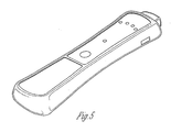
- FIG. 5 shows a three-dimensional view of an embodiment of a tire positioning tool according to the present invention.
Claims (14)
- Outil (100) comprenant :une pluralité de moyens pour activer des capteurs de pneus (206) d'un système de surveillance à distance de pneus, la pluralité de moyens étant choisis dans le groupe constitué d'un aimant (102), un dépresseur d'embout de valve, un moyen pour générer des signaux d'onde continue (108, 124, 126) et un moyen (114) pour générer des signaux modulés ;une pluralité de moyens (118, 120) pour recevoir des signaux de capteurs de pneus ;caractérisé en ce que l'outil comprend un moyen d'enregistrement pour enregistrer le type de signal d'activation correct le plus récent.
- Outil selon la revendication 1, dans lequel l'outil comprend un aimant (102) et au moins un moyen pour générer un signal d'onde continue (108).
- Outil selon la revendication 1 ou 2, dans lequel l'outil comprend un aimant et au moins un moyen pour générer un signal modulé.
- Outil selon la revendication 1, 2 ou 3, dans lequel l'outil comprend une pluralité de moyens pour générer des signaux d'onde continue (108) et/ou dans lequel l'outil comprend une pluralité de moyens pour générer des signaux modulés.
- Outil selon l'une quelconque des revendications précédentes, comprenant en outre un moyen pour recevoir des signaux de capteurs de pneus (118).
- Outil selon l'une quelconque des revendications précédentes, comprenant en outre une pluralité de moyens pour recevoir des signaux de capteurs de pneus (118, 120).
- Outil selon la revendication 5 ou 6, dans lequel le moyen pour recevoir des signaux de capteurs de pneus (118, 120) est choisi dans le groupe de moyens capables de recevoir des signaux de capteurs de pneus à des fréquences de 125 kHz, 13,56 MHz, 315 MHz, 433 MHz, 848 MHz, 916 MHz et 2,4 GHz.
- Outil selon l'une quelconque des revendications précédentes, comprenant en outre :un moyen pour recevoir des signaux de capteurs de pneus (118, 120) ; etun dispositif d'affichage (128) pour afficher les données reçues des signaux de capteurs de pneus.
- Outil selon la revendication 8, dans lequel le dispositif d'affichage (128) est un dispositif à LED, un dispositif à LCD ou un dispositif VF.
- Outil selon l'une quelconque des revendications précédentes, comprenant en outre :un moyen pour recevoir des signaux de capteurs de pneus (118, 120) ; etun moyen pour transmettre des signaux (124, 126) aux unités de réception du système de surveillance à distance de pneus.
- Outil selon la revendication 10, dans lequel le moyen pour transmettre des signaux (124, 126) aux unités de réception de surveillance à distance de pneus est choisi dans le groupe de moyens capables de transmettre des signaux à des fréquences de 125 kHz, 13,56 MHz, 315 MHz, 433 MHz, 848 MHz, 916 MHz et 2,4 GHz.
- Outil selon l'une quelconque des revendications précédentes, comprenant en outre :un moyen pour recevoir des signaux de capteurs de pneus (118, 120) ;un moyen pour transmettre des signaux (124, 126) aux unités de réception du système de surveillance à distance de pneus ; etun moyen pour recevoir des signaux transmis par les unités de réception du système de surveillance à distance de pneus (118, 120).
- Procédé comprenant les étapes consistant à :essayer d'activer un capteur de pneu d'un système de surveillance à distance de pneus (206) en utilisant un premier moyen pour activer des capteurs de pneus du système de surveillance à distance de pneus ;attendre la réception d'un signal de capteur de pneu (210) ;essayer d'activer le capteur de pneu du système de surveillance à distance de pneus (212) en utilisant un moyen différent pour activer les capteurs de pneus du système de surveillance à distance de pneus si aucun signal de capteur de pneu n'a été reçu ; etrépéter l'étape d'attente et la deuxième étape d'essai jusqu'à ce que, soit un signal de capteur de pneu soit reçu, soit qu'aucun moyen différent pour activer les capteurs de pneus du système de surveillance à distance de pneus ne soit disponible (210, 212), caractérisé en ce que :le procédé comprend l'étape d'enregistrement du moyen le plus récent utilisé pour tenter d'activer le capteur de pneu de surveillance à distance de pneus si un signal de capteur de pneu est reçu (214).
- Procédé selon la revendication 13, comprenant l'étape consistant à :activer un deuxième capteur de pneu du système de surveillance à distance de pneus en utilisant le moyen enregistré.
Applications Claiming Priority (2)
| Application Number | Priority Date | Filing Date | Title |
|---|---|---|---|
| US10/420,175 US6904796B2 (en) | 2003-04-21 | 2003-04-21 | Remote tire monitoring systems tool |
| PCT/US2004/012281 WO2004094167A1 (fr) | 2003-04-21 | 2004-04-21 | Outil pour systemes de telesurveillance |
Publications (3)
| Publication Number | Publication Date |
|---|---|
| EP1615785A1 EP1615785A1 (fr) | 2006-01-18 |
| EP1615785A4 EP1615785A4 (fr) | 2009-05-27 |
| EP1615785B1 true EP1615785B1 (fr) | 2013-01-02 |
Family
ID=33159386
Family Applications (1)
| Application Number | Title | Priority Date | Filing Date |
|---|---|---|---|
| EP04760072A Expired - Lifetime EP1615785B1 (fr) | 2003-04-21 | 2004-04-21 | Outil pour systemes de telesurveillance |
Country Status (7)
| Country | Link |
|---|---|
| US (1) | US6904796B2 (fr) |
| EP (1) | EP1615785B1 (fr) |
| JP (3) | JP2006523562A (fr) |
| AU (1) | AU2004233319B2 (fr) |
| CA (1) | CA2523204C (fr) |
| ES (1) | ES2415054T3 (fr) |
| WO (1) | WO2004094167A1 (fr) |
Families Citing this family (107)
| Publication number | Priority date | Publication date | Assignee | Title |
|---|---|---|---|---|
| US8872517B2 (en) | 1996-07-29 | 2014-10-28 | Midtronics, Inc. | Electronic battery tester with battery age input |
| US7706991B2 (en) | 1996-07-29 | 2010-04-27 | Midtronics, Inc. | Alternator tester |
| US8198900B2 (en) | 1996-07-29 | 2012-06-12 | Midtronics, Inc. | Automotive battery charging system tester |
| US6850037B2 (en) | 1997-11-03 | 2005-02-01 | Midtronics, Inc. | In-vehicle battery monitor |
| US6566883B1 (en) | 1999-11-01 | 2003-05-20 | Midtronics, Inc. | Electronic battery tester |
| US7688074B2 (en) | 1997-11-03 | 2010-03-30 | Midtronics, Inc. | Energy management system for automotive vehicle |
| US7774151B2 (en) | 1997-11-03 | 2010-08-10 | Midtronics, Inc. | Wireless battery monitor |
| US8958998B2 (en) | 1997-11-03 | 2015-02-17 | Midtronics, Inc. | Electronic battery tester with network communication |
| US7705602B2 (en) * | 1997-11-03 | 2010-04-27 | Midtronics, Inc. | Automotive vehicle electrical system diagnostic device |
| US7446536B2 (en) | 2000-03-27 | 2008-11-04 | Midtronics, Inc. | Scan tool for electronic battery tester |
| US8513949B2 (en) | 2000-03-27 | 2013-08-20 | Midtronics, Inc. | Electronic battery tester or charger with databus connection |
| US7398176B2 (en) | 2000-03-27 | 2008-07-08 | Midtronics, Inc. | Battery testers with secondary functionality |
| US7154276B2 (en) | 2003-09-05 | 2006-12-26 | Midtronics, Inc. | Method and apparatus for measuring a parameter of a vehicle electrical system |
| US9255955B2 (en) | 2003-09-05 | 2016-02-09 | Midtronics, Inc. | Method and apparatus for measuring a parameter of a vehicle electrical system |
| US8164343B2 (en) | 2003-09-05 | 2012-04-24 | Midtronics, Inc. | Method and apparatus for measuring a parameter of a vehicle electrical system |
| US9018958B2 (en) | 2003-09-05 | 2015-04-28 | Midtronics, Inc. | Method and apparatus for measuring a parameter of a vehicle electrical system |
| US7977914B2 (en) | 2003-10-08 | 2011-07-12 | Midtronics, Inc. | Battery maintenance tool with probe light |
| US7777612B2 (en) | 2004-04-13 | 2010-08-17 | Midtronics, Inc. | Theft prevention device for automotive vehicle service centers |
| JP4325496B2 (ja) * | 2004-06-28 | 2009-09-02 | 富士電機システムズ株式会社 | タイヤ空気圧監視装置 |
| US7772850B2 (en) | 2004-07-12 | 2010-08-10 | Midtronics, Inc. | Wireless battery tester with information encryption means |
| CN100546822C (zh) * | 2004-07-13 | 2009-10-07 | 汉高公司 | 用于高度充填的相变热界面材料的新型封装方案 |
| US8436619B2 (en) | 2004-08-20 | 2013-05-07 | Midtronics, Inc. | Integrated tag reader and environment sensor |
| US8344685B2 (en) | 2004-08-20 | 2013-01-01 | Midtronics, Inc. | System for automatically gathering battery information |
| US8442877B2 (en) | 2004-08-20 | 2013-05-14 | Midtronics, Inc. | Simplification of inventory management |
| US9496720B2 (en) | 2004-08-20 | 2016-11-15 | Midtronics, Inc. | System for automatically gathering battery information |
| US7710119B2 (en) | 2004-12-09 | 2010-05-04 | Midtronics, Inc. | Battery tester that calculates its own reference values |
| US7204136B2 (en) * | 2004-12-22 | 2007-04-17 | Tyco Electronics Corporation | Tire pressure sensor housing |
| JP2006242707A (ja) * | 2005-03-02 | 2006-09-14 | Denso Corp | タイヤ空気圧検出装置 |
| EP1976713A2 (fr) * | 2005-11-08 | 2008-10-08 | TRW Automotive U.S. LLC | Contrôleur de pression pour pneumatique |
| FR2895126B1 (fr) | 2005-12-15 | 2008-03-14 | Renault Sas | Procede et systeme de transmission d'un identifiant d'une valve d'une roue d'un vehicule a un recepteur de bord de ce vehicule |
| JP4812432B2 (ja) * | 2006-01-10 | 2011-11-09 | 株式会社ブリヂストン | タイヤ点検装置、タイヤ点検システム及びタイヤ点検方法 |
| US7592904B2 (en) * | 2006-10-30 | 2009-09-22 | Spx Corporation | Tire pressure monitor system module |
| US7639122B2 (en) * | 2006-10-30 | 2009-12-29 | Spx Corporation | Tire pressure monitor system tool with vehicle entry system |
| US7592903B2 (en) | 2006-10-30 | 2009-09-22 | Spx Corporation | Tire pressure monitor system tool with re-learn and diagnostic procedures |
| US7623025B2 (en) * | 2006-10-30 | 2009-11-24 | Spx Corporation | Tire pressure monitor initiation tool with vehicle data interface |
| US20080117036A1 (en) * | 2006-11-17 | 2008-05-22 | Thomas Kenny | Programmable wireless sensors |
| US7688192B2 (en) * | 2006-11-17 | 2010-03-30 | G-5 Electronics, Llc | Programming wireless sensors |
| GB0623802D0 (en) * | 2006-11-29 | 2007-01-10 | Brown Duncan | An arrangement of interconnected devices or system to indicate loading state or overload of the axles on a vehicle |
| US20080164846A1 (en) * | 2007-01-08 | 2008-07-10 | Snap-On Incorporated | Apparatus and method to update and maintain a tire pressure monitoring tool |
| US7589619B2 (en) * | 2007-01-08 | 2009-09-15 | Snap-On Incorporated | Apparatus and method to transfer data from a tire pressure monitor tool to a remote output device such as a printer |
| US7791348B2 (en) | 2007-02-27 | 2010-09-07 | Midtronics, Inc. | Battery tester with promotion feature to promote use of the battery tester by providing the user with codes having redeemable value |
| US7808375B2 (en) | 2007-04-16 | 2010-10-05 | Midtronics, Inc. | Battery run down indicator |
| CN103112324B (zh) | 2007-07-03 | 2016-01-27 | 欧陆汽车系统美国有限公司 | 通用轮胎压力监测传感器 |
| US9274157B2 (en) | 2007-07-17 | 2016-03-01 | Midtronics, Inc. | Battery tester for electric vehicle |
| US8306690B2 (en) | 2007-07-17 | 2012-11-06 | Midtronics, Inc. | Battery tester for electric vehicle |
| US7487671B1 (en) * | 2007-08-18 | 2009-02-10 | Silicon Valley Micro C Corp. | Tire parameter monitoring system with sensor location using magnetic fields |
| US7940164B2 (en) * | 2007-11-11 | 2011-05-10 | Doran Manufacturing Llc | Method for programming new sensor in a motor vehicle monitoring system |
| CN101515023A (zh) | 2007-12-06 | 2009-08-26 | 密特电子公司 | 蓄电池和电池测试器 |
| US8770254B1 (en) | 2008-07-17 | 2014-07-08 | Hunter Engineering Company | Tire changer with rotational position and tracking control |
| US7884707B2 (en) * | 2008-04-23 | 2011-02-08 | Spx Corporation | Tire pressure monitor system tool with parts number database |
| US9073394B1 (en) | 2008-07-17 | 2015-07-07 | Hunter Engineering Company | Tire changing machine with force detection and control methods |
| DE102009044573A1 (de) * | 2009-11-18 | 2011-05-19 | Continental Reifen Deutschland Gmbh | Verfahren zum Detektieren eines von einer Reifeninnenseite losgelösten Reifenmoduls für Fahrzeuge |
| US9588185B2 (en) | 2010-02-25 | 2017-03-07 | Keith S. Champlin | Method and apparatus for detecting cell deterioration in an electrochemical cell or battery |
| US8528393B2 (en) * | 2010-02-26 | 2013-09-10 | Schrader Electronics Ltd. | Wheel position determination using revolution counter |
| CN102804478B (zh) | 2010-03-03 | 2015-12-16 | 密特电子公司 | 用于前部接线端电池的监控器 |
| US9229062B2 (en) | 2010-05-27 | 2016-01-05 | Midtronics, Inc. | Electronic storage battery diagnostic system |
| US8738309B2 (en) | 2010-09-30 | 2014-05-27 | Midtronics, Inc. | Battery pack maintenance for electric vehicles |
| US10046649B2 (en) | 2012-06-28 | 2018-08-14 | Midtronics, Inc. | Hybrid and electric vehicle battery pack maintenance device |
| JP5829681B2 (ja) | 2010-06-03 | 2015-12-09 | ミッドトロニクス インコーポレイテッド | 電気自動車用バッテリパックのメンテナンス |
| US11740294B2 (en) | 2010-06-03 | 2023-08-29 | Midtronics, Inc. | High use battery pack maintenance |
| US9419311B2 (en) | 2010-06-18 | 2016-08-16 | Midtronics, Inc. | Battery maintenance device with thermal buffer |
| US9201120B2 (en) | 2010-08-12 | 2015-12-01 | Midtronics, Inc. | Electronic battery tester for testing storage battery |
| JP5552396B2 (ja) * | 2010-08-18 | 2014-07-16 | 為升電装工業股▲分▼有限公司 | タイヤ監視測定装置の使用方法 |
| US20120050029A1 (en) * | 2010-08-27 | 2012-03-01 | San-Chuan Yu | Programmable tire monitoring device and its method of use |
| US8751092B2 (en) | 2011-01-13 | 2014-06-10 | Continental Automotive Systems, Inc. | Protocol protection |
| US8680980B2 (en) * | 2011-02-28 | 2014-03-25 | Cub Elecparts Inc. | Blank tire pressure monitoring device and its setup method |
| US8576060B2 (en) | 2011-08-09 | 2013-11-05 | Continental Automotive Systems, Inc. | Protocol arrangement in a tire pressure monitoring system |
| KR101599780B1 (ko) | 2011-08-09 | 2016-03-04 | 컨티넨탈 오토모티브 시스템즈 인코포레이티드 | 타이어 압력 모니터링 시스템을 위한 프로토콜 오해 회피 장치 및 방법 |
| EP2741928B1 (fr) | 2011-08-09 | 2019-10-09 | Continental Automotive Systems, Inc. | Appareil et procédé de surveillance de pression de pneu |
| US9676238B2 (en) | 2011-08-09 | 2017-06-13 | Continental Automotive Systems, Inc. | Tire pressure monitor system apparatus and method |
| EP2741927B1 (fr) | 2011-08-09 | 2017-04-26 | Continental Automotive Systems, Inc. | Appareil et procédé d'activation d'un procédé de localisation pour un dispositif de surveillance de pression de pneu |
| US9050862B2 (en) | 2011-10-26 | 2015-06-09 | Ateq Corporation | Universal tire pressure monitoring system tool and methods |
| WO2013070850A2 (fr) | 2011-11-10 | 2013-05-16 | Midtronics, Inc. | Testeur de batterie |
| US9091537B2 (en) | 2012-04-18 | 2015-07-28 | Bosch Automotive Service Solutions Inc. | Tire pressure monitor system tool with active tire pressure display |
| US9851411B2 (en) | 2012-06-28 | 2017-12-26 | Keith S. Champlin | Suppressing HF cable oscillations during dynamic measurements of cells and batteries |
| US11325479B2 (en) | 2012-06-28 | 2022-05-10 | Midtronics, Inc. | Hybrid and electric vehicle battery maintenance device |
| NO2833907T3 (fr) | 2012-11-02 | 2018-07-28 | ||
| US9120357B2 (en) * | 2013-03-15 | 2015-09-01 | Continental Automotive Systems, Inc. | Methods, systems and devices for integration of tire pressure monitoring sensors with a tire pressure monitoring system |
| US9244100B2 (en) | 2013-03-15 | 2016-01-26 | Midtronics, Inc. | Current clamp with jaw closure detection |
| TW201441069A (zh) * | 2013-04-25 | 2014-11-01 | Cub Elecparts Inc | 胎壓感應器之設定工具 |
| TW201442891A (zh) * | 2013-05-06 | 2014-11-16 | Cub Elecparts Inc | 磁力傳輸式胎壓感測器及設定工具與設定方法 |
| US9312575B2 (en) | 2013-05-16 | 2016-04-12 | Midtronics, Inc. | Battery testing system and method |
| EP2813379B1 (fr) * | 2013-06-11 | 2015-08-19 | CUB Elecparts Inc. | Dispositif de capteur de pression de pneu de type transmission de force magnétique et outil et procédé de réglage associés |
| WO2015009599A1 (fr) * | 2013-07-15 | 2015-01-22 | Continental Automotive Systems, Inc. | Procédés, systèmes et dispositifs pour enregistrer et transmettre une information d'identification de capteurs de contrôle de pression de pneu à un véhicule |
| CN103332076B (zh) * | 2013-07-19 | 2015-12-02 | 上海为彪汽配制造有限公司 | 磁力传输式胎压传感器及设定工具与设定方法 |
| US10843574B2 (en) | 2013-12-12 | 2020-11-24 | Midtronics, Inc. | Calibration and programming of in-vehicle battery sensors |
| US9923289B2 (en) | 2014-01-16 | 2018-03-20 | Midtronics, Inc. | Battery clamp with endoskeleton design |
| US9446636B2 (en) | 2014-02-26 | 2016-09-20 | Continental Automotive Systems, Inc. | Pressure check tool and method of operating the same |
| US10473555B2 (en) | 2014-07-14 | 2019-11-12 | Midtronics, Inc. | Automotive maintenance system |
| US10222397B2 (en) | 2014-09-26 | 2019-03-05 | Midtronics, Inc. | Cable connector for electronic battery tester |
| WO2016123075A1 (fr) | 2015-01-26 | 2016-08-04 | Midtronics, Inc. | Dispositif d'essai d'un alternateur |
| US9517664B2 (en) | 2015-02-20 | 2016-12-13 | Continental Automotive Systems, Inc. | RF transmission method and apparatus in a tire pressure monitoring system |
| US9579938B2 (en) * | 2015-06-01 | 2017-02-28 | Continental Automotive Systems, Inc. | Apparatus and method to adjust LF sensitivity of TPM sensor |
| DE102016213290A1 (de) | 2015-08-03 | 2017-02-09 | Continental Automotive Systems, Inc. | Vorrichtung, System und Verfahren zum Konfigurieren eines Reifeninformationssensors mit einem Übertragungsprotokoll auf der Basis von Fahrzeugtriggerkenngrößen |
| US9966676B2 (en) | 2015-09-28 | 2018-05-08 | Midtronics, Inc. | Kelvin connector adapter for storage battery |
| US10608353B2 (en) | 2016-06-28 | 2020-03-31 | Midtronics, Inc. | Battery clamp |
| US11054480B2 (en) | 2016-10-25 | 2021-07-06 | Midtronics, Inc. | Electrical load for electronic battery tester and electronic battery tester including such electrical load |
| US11724552B2 (en) * | 2017-12-05 | 2023-08-15 | Pacific Industrial Co., Ltd. | Transmitter for wheel assemblies |
| WO2019111330A1 (fr) * | 2017-12-05 | 2019-06-13 | 太平洋工業 株式会社 | Émetteur et dispositif de surveillance d'état de pneu |
| US11513160B2 (en) | 2018-11-29 | 2022-11-29 | Midtronics, Inc. | Vehicle battery maintenance device |
| US11566972B2 (en) | 2019-07-31 | 2023-01-31 | Midtronics, Inc. | Tire tread gauge using visual indicator |
| US11545839B2 (en) | 2019-11-05 | 2023-01-03 | Midtronics, Inc. | System for charging a series of connected batteries |
| US11668779B2 (en) | 2019-11-11 | 2023-06-06 | Midtronics, Inc. | Hybrid and electric vehicle battery pack maintenance device |
| US11474153B2 (en) | 2019-11-12 | 2022-10-18 | Midtronics, Inc. | Battery pack maintenance system |
| US11486930B2 (en) | 2020-01-23 | 2022-11-01 | Midtronics, Inc. | Electronic battery tester with battery clamp storage holsters |
| US11400772B2 (en) * | 2020-02-26 | 2022-08-02 | Ateq | Scanning method and device for tire pressure monitoring system (tpms) protocols |
| FR3109850B1 (fr) | 2020-04-29 | 2022-12-30 | Ateq | Dispositif pour systeme electronique de controle de la pression des pneus d’un vehicule automobile |
Family Cites Families (29)
| Publication number | Priority date | Publication date | Assignee | Title |
|---|---|---|---|---|
| US4966034A (en) | 1988-04-28 | 1990-10-30 | Schrader Automotive, Inc. | On-board tire pressure indicating system performing temperature-compensated pressure measurement, and pressure measurement circuitry thereof |
| US4951501A (en) | 1989-10-16 | 1990-08-28 | Schrader Automotive Inc. | Tire valve having dual electric conducting paths |
| US6662642B2 (en) * | 2000-09-08 | 2003-12-16 | Automotive Technologies International, Inc. | Vehicle wireless sensing and communication system |
| US5302939A (en) | 1992-09-08 | 1994-04-12 | Schrader Automotive Inc. | Dual tire equalizer having remote indicator |
| US5600301A (en) * | 1993-03-11 | 1997-02-04 | Schrader Automotive Inc. | Remote tire pressure monitoring system employing coded tire identification and radio frequency transmission, and enabling recalibration upon tire rotation or replacement |
| US5963128A (en) | 1994-11-22 | 1999-10-05 | Schrader-Bridgeport International, Inc. | Remote tire pressure monitoring system |
| JP3111374B2 (ja) * | 1995-03-08 | 2000-11-20 | 横河電機株式会社 | タイヤ圧力モニタシステム |
| JPH08293870A (ja) * | 1995-04-24 | 1996-11-05 | Nissan Motor Co Ltd | 通信設備 |
| US5838229A (en) | 1995-07-18 | 1998-11-17 | Schrader-Bridgeport International, Inc. | Remote tire pressure monitoring system employing coded tire identification and radio frequency transmission and enabling recalibration upon tire rotation or replacement |
| US6005480A (en) | 1998-05-20 | 1999-12-21 | Schrader-Bridgeport International, Inc. | Tire valve and associated tire pressure sending unit |
| JPH11345386A (ja) * | 1998-05-29 | 1999-12-14 | Denso Corp | ガス濃度検出装置 |
| US6486773B1 (en) | 1998-09-10 | 2002-11-26 | Schrader-Bridgeport International, Inc. | Method for communicating data in a remote tire pressure monitoring system |
| JP3401535B2 (ja) * | 1998-09-29 | 2003-04-28 | 太平洋工業株式会社 | タイヤ空気圧監視システム |
| US6043739A (en) | 1998-10-21 | 2000-03-28 | Henderson; Maurice Larue | HyperVision auxiliary taillight array |
| JP4076290B2 (ja) * | 1999-01-13 | 2008-04-16 | 横浜ゴム株式会社 | タイヤ状態監視装置 |
| US6710708B2 (en) * | 1999-02-05 | 2004-03-23 | Schrader-Bridgeport International, Inc. | Method and apparatus for a remote tire pressure monitoring system |
| FR2790115B1 (fr) | 1999-02-23 | 2001-05-04 | Micro Controle | Procede et dispositif pour deplacer un mobile sur une base montee elastiquement par rapport au sol |
| DE19908701B4 (de) * | 1999-02-26 | 2005-04-14 | Continental Teves Ag & Co. Ohg | Verfahren und Vorrichtung zur Ermittlung des Notlaufzustandes eines Luftreifens |
| DE19917034C1 (de) * | 1999-04-15 | 2000-11-23 | Continental Ag | Verfahren zur Überwachung des Luftdrucks der Reifen eines Kraftfahrzeuges |
| US6204758B1 (en) | 1999-07-23 | 2001-03-20 | Schrader-Bridgeport International, Inc. | System to automatically determine wheel position for automotive remote tire monitoring system |
| DE60024574T2 (de) | 1999-12-20 | 2006-08-24 | Trw Automotive U.S. Llc, Livonia | Vorrichtung und Verfahren zur Überprüfung des Betriebszustandes eines Fahrzeugreifens |
| US6417766B1 (en) | 2000-01-14 | 2002-07-09 | Schrader-Bridgeport International, Inc. | Method and apparatus for identifying remote sending units in a tire pressure monitor system of a vehicle using secondary modulation of wheel rotation |
| US6507276B1 (en) | 2000-06-12 | 2003-01-14 | Cm Automotive Systems Inc. | Tire pressure monitoring system |
| NO20013182L (no) * | 2000-06-26 | 2001-12-27 | Nokian Tyres Plc | System og fremgangsmåte for konvertering og overföring av driftsdata for dekk |
| US20020130771A1 (en) | 2000-08-17 | 2002-09-19 | Osborne Corwin K. | Vehicle wheel monitoring system |
| GB0030405D0 (en) * | 2000-12-13 | 2001-01-24 | Transense Technologies Plc | Wheel condition monitoring system |
| US6414592B1 (en) * | 2001-01-02 | 2002-07-02 | Trw Inc. | Tire condition sensor communication with tire location provided via manually inputted update |
| JP2003002020A (ja) * | 2001-06-19 | 2003-01-08 | Matsushita Electric Ind Co Ltd | タイヤ空気圧検出システム |
| JP2003063220A (ja) * | 2001-08-30 | 2003-03-05 | Nippon Seiki Co Ltd | タイヤ空気圧監視装置 |
-
2003
- 2003-04-21 US US10/420,175 patent/US6904796B2/en not_active Expired - Lifetime
-
2004
- 2004-04-21 CA CA002523204A patent/CA2523204C/fr not_active Expired - Fee Related
- 2004-04-21 AU AU2004233319A patent/AU2004233319B2/en not_active Ceased
- 2004-04-21 ES ES04760072T patent/ES2415054T3/es not_active Expired - Lifetime
- 2004-04-21 EP EP04760072A patent/EP1615785B1/fr not_active Expired - Lifetime
- 2004-04-21 JP JP2006501287A patent/JP2006523562A/ja active Pending
- 2004-04-21 WO PCT/US2004/012281 patent/WO2004094167A1/fr active Search and Examination
-
2010
- 2010-01-04 JP JP2010000206A patent/JP5887572B2/ja not_active Expired - Fee Related
-
2013
- 2013-10-07 JP JP2013210130A patent/JP6348268B2/ja not_active Expired - Fee Related
Also Published As
| Publication number | Publication date |
|---|---|
| CA2523204A1 (fr) | 2004-11-04 |
| JP2014000962A (ja) | 2014-01-09 |
| ES2415054T3 (es) | 2013-07-23 |
| AU2004233319B2 (en) | 2007-12-20 |
| CA2523204C (fr) | 2009-08-25 |
| EP1615785A1 (fr) | 2006-01-18 |
| US20040206167A1 (en) | 2004-10-21 |
| JP2010159048A (ja) | 2010-07-22 |
| AU2004233319A1 (en) | 2004-11-04 |
| EP1615785A4 (fr) | 2009-05-27 |
| JP5887572B2 (ja) | 2016-03-16 |
| US6904796B2 (en) | 2005-06-14 |
| JP2006523562A (ja) | 2006-10-19 |
| WO2004094167A1 (fr) | 2004-11-04 |
| JP6348268B2 (ja) | 2018-06-27 |
Similar Documents
| Publication | Publication Date | Title |
|---|---|---|
| EP1615785B1 (fr) | Outil pour systemes de telesurveillance | |
| US6750761B1 (en) | Method for monitoring tire parameters | |
| US6788193B2 (en) | System and method for tire pressure monitoring providing automatic tire location recognition | |
| US7518495B2 (en) | Universal tire pressure monitor | |
| US6838985B2 (en) | System and method for remote tire pressure monitoring with low frequency initiation | |
| US7592904B2 (en) | Tire pressure monitor system module | |
| US6612165B2 (en) | Tire pressure monitoring system with pressure gauge operating mode for indicating when air pressure within a tire is within a predetermined pressure range | |
| US20020003474A1 (en) | Method and apparatus for a remote tire pressure monitoring system | |
| US7327233B2 (en) | Method and a device for locating the position of wheels of a vehicle | |
| EP1614550B1 (fr) | Systeme d'acquisition de donnees de roue et dispositif de determination d'information de position d'installation de roue | |
| EP1197356A2 (fr) | Communication de capteur de condition de pneumatique contrôlée par le véhicule utilisant une identification fixe de pneumatique | |
| GB2385929A (en) | A system for identifying tyre location | |
| JP2001108551A (ja) | タイヤ空気圧監視装置及び外部通信装置 | |
| US6691567B2 (en) | System and method for tire pressure monitoring including automatic tire location recognition | |
| JP5710458B2 (ja) | 無線式タイヤ空気圧感知装置、その標準タイヤ空気圧設定方法及び無線式タイヤ空気圧力感知作動装置 | |
| GB2443302A (en) | Tyre pressure monitoring system and method | |
| US20030164759A1 (en) | System and method for tire pressure monitoring with optimal tire pressure indication during tire pressure adjustment | |
| US6725712B1 (en) | System and method for tire pressure monitoring with automatic tire location recognition | |
| CN115175819A (zh) | 用于胎压监测系统(tpms)协议的扫描方法和装置 | |
| US8026803B2 (en) | Apparatus and process for monitoring a vehicle condition | |
| WO2010056860A1 (fr) | Indicateur d'état de véhicule basse puissance, embarqué | |
| CA2524206C (fr) | Methode et appareil pour systeme de controle a distance de la pression des pneus |
Legal Events
| Date | Code | Title | Description |
|---|---|---|---|
| PUAI | Public reference made under article 153(3) epc to a published international application that has entered the european phase |
Free format text: ORIGINAL CODE: 0009012 |
|
| 17P | Request for examination filed |
Effective date: 20050912 |
|
| AK | Designated contracting states |
Kind code of ref document: A1 Designated state(s): AT BE BG CH CY CZ DE DK EE ES FI FR GB GR HU IE IT LI LU MC NL PL PT RO SE SI SK TR |
|
| AX | Request for extension of the european patent |
Extension state: AL HR LT LV MK |
|
| DAX | Request for extension of the european patent (deleted) | ||
| A4 | Supplementary search report drawn up and despatched |
Effective date: 20090423 |
|
| RIC1 | Information provided on ipc code assigned before grant |
Ipc: B60C 23/04 20060101AFI20090417BHEP |
|
| 17Q | First examination report despatched |
Effective date: 20090708 |
|
| GRAP | Despatch of communication of intention to grant a patent |
Free format text: ORIGINAL CODE: EPIDOSNIGR1 |
|
| RAP1 | Party data changed (applicant data changed or rights of an application transferred) |
Owner name: SPX CORPORATION |
|
| GRAS | Grant fee paid |
Free format text: ORIGINAL CODE: EPIDOSNIGR3 |
|
| GRAA | (expected) grant |
Free format text: ORIGINAL CODE: 0009210 |
|
| AK | Designated contracting states |
Kind code of ref document: B1 Designated state(s): AT BE BG CH CY CZ DE DK EE ES FI FR GB GR HU IE IT LI LU MC NL PL PT RO SE SI SK TR |
|
| REG | Reference to a national code |
Ref country code: GB Ref legal event code: FG4D |
|
| REG | Reference to a national code |
Ref country code: CH Ref legal event code: EP Ref country code: AT Ref legal event code: REF Ref document number: 591383 Country of ref document: AT Kind code of ref document: T Effective date: 20130115 |
|
| REG | Reference to a national code |
Ref country code: IE Ref legal event code: FG4D |
|
| REG | Reference to a national code |
Ref country code: DE Ref legal event code: R096 Ref document number: 602004040642 Country of ref document: DE Effective date: 20130228 |
|
| REG | Reference to a national code |
Ref country code: AT Ref legal event code: MK05 Ref document number: 591383 Country of ref document: AT Kind code of ref document: T Effective date: 20130102 |
|
| REG | Reference to a national code |
Ref country code: NL Ref legal event code: VDEP Effective date: 20130102 |
|
| PG25 | Lapsed in a contracting state [announced via postgrant information from national office to epo] |
Ref country code: SI Free format text: LAPSE BECAUSE OF FAILURE TO SUBMIT A TRANSLATION OF THE DESCRIPTION OR TO PAY THE FEE WITHIN THE PRESCRIBED TIME-LIMIT Effective date: 20130102 |
|
| REG | Reference to a national code |
Ref country code: GB Ref legal event code: 732E Free format text: REGISTERED BETWEEN 20130530 AND 20130605 |
|
| RAP2 | Party data changed (patent owner data changed or rights of a patent transferred) |
Owner name: SERVICE SOLUTIONS U.S. LLC |
|
| REG | Reference to a national code |
Ref country code: ES Ref legal event code: FG2A Ref document number: 2415054 Country of ref document: ES Kind code of ref document: T3 Effective date: 20130723 |
|
| REG | Reference to a national code |
Ref country code: DE Ref legal event code: R081 Ref document number: 602004040642 Country of ref document: DE Owner name: SERVICE SOLUTIONS U.S. LLC, US Free format text: FORMER OWNER: SPX CORPORATION, CHARLOTTE, US Effective date: 20130603 Ref country code: DE Ref legal event code: R081 Ref document number: 602004040642 Country of ref document: DE Owner name: SERVICE SOLUTIONS U.S. LLC, US Free format text: FORMER OWNER: G-5 ELECTRONICS, TROY, US Effective date: 20130103 Ref country code: DE Ref legal event code: R081 Ref document number: 602004040642 Country of ref document: DE Owner name: SERVICE SOLUTIONS U.S. LLC, WARREN, US Free format text: FORMER OWNER: SPX CORPORATION, CHARLOTTE, N.C., US Effective date: 20130603 Ref country code: DE Ref legal event code: R081 Ref document number: 602004040642 Country of ref document: DE Owner name: SERVICE SOLUTIONS U.S. LLC, WARREN, US Free format text: FORMER OWNER: G-5 ELECTRONICS, TROY, MICH., US Effective date: 20130103 |
|
| PG25 | Lapsed in a contracting state [announced via postgrant information from national office to epo] |
Ref country code: AT Free format text: LAPSE BECAUSE OF FAILURE TO SUBMIT A TRANSLATION OF THE DESCRIPTION OR TO PAY THE FEE WITHIN THE PRESCRIBED TIME-LIMIT Effective date: 20130102 Ref country code: BG Free format text: LAPSE BECAUSE OF FAILURE TO SUBMIT A TRANSLATION OF THE DESCRIPTION OR TO PAY THE FEE WITHIN THE PRESCRIBED TIME-LIMIT Effective date: 20130402 Ref country code: CY Free format text: LAPSE BECAUSE OF FAILURE TO SUBMIT A TRANSLATION OF THE DESCRIPTION OR TO PAY THE FEE WITHIN THE PRESCRIBED TIME-LIMIT Effective date: 20130102 Ref country code: CZ Free format text: LAPSE BECAUSE OF FAILURE TO SUBMIT A TRANSLATION OF THE DESCRIPTION OR TO PAY THE FEE WITHIN THE PRESCRIBED TIME-LIMIT Effective date: 20130102 Ref country code: BE Free format text: LAPSE BECAUSE OF FAILURE TO SUBMIT A TRANSLATION OF THE DESCRIPTION OR TO PAY THE FEE WITHIN THE PRESCRIBED TIME-LIMIT Effective date: 20130102 Ref country code: SE Free format text: LAPSE BECAUSE OF FAILURE TO SUBMIT A TRANSLATION OF THE DESCRIPTION OR TO PAY THE FEE WITHIN THE PRESCRIBED TIME-LIMIT Effective date: 20130102 |
|
| PG25 | Lapsed in a contracting state [announced via postgrant information from national office to epo] |
Ref country code: GR Free format text: LAPSE BECAUSE OF FAILURE TO SUBMIT A TRANSLATION OF THE DESCRIPTION OR TO PAY THE FEE WITHIN THE PRESCRIBED TIME-LIMIT Effective date: 20130403 Ref country code: PL Free format text: LAPSE BECAUSE OF FAILURE TO SUBMIT A TRANSLATION OF THE DESCRIPTION OR TO PAY THE FEE WITHIN THE PRESCRIBED TIME-LIMIT Effective date: 20130102 Ref country code: FI Free format text: LAPSE BECAUSE OF FAILURE TO SUBMIT A TRANSLATION OF THE DESCRIPTION OR TO PAY THE FEE WITHIN THE PRESCRIBED TIME-LIMIT Effective date: 20130102 Ref country code: PT Free format text: LAPSE BECAUSE OF FAILURE TO SUBMIT A TRANSLATION OF THE DESCRIPTION OR TO PAY THE FEE WITHIN THE PRESCRIBED TIME-LIMIT Effective date: 20130502 Ref country code: NL Free format text: LAPSE BECAUSE OF FAILURE TO SUBMIT A TRANSLATION OF THE DESCRIPTION OR TO PAY THE FEE WITHIN THE PRESCRIBED TIME-LIMIT Effective date: 20130102 |
|
| PG25 | Lapsed in a contracting state [announced via postgrant information from national office to epo] |
Ref country code: EE Free format text: LAPSE BECAUSE OF FAILURE TO SUBMIT A TRANSLATION OF THE DESCRIPTION OR TO PAY THE FEE WITHIN THE PRESCRIBED TIME-LIMIT Effective date: 20130102 Ref country code: DK Free format text: LAPSE BECAUSE OF FAILURE TO SUBMIT A TRANSLATION OF THE DESCRIPTION OR TO PAY THE FEE WITHIN THE PRESCRIBED TIME-LIMIT Effective date: 20130102 Ref country code: RO Free format text: LAPSE BECAUSE OF FAILURE TO SUBMIT A TRANSLATION OF THE DESCRIPTION OR TO PAY THE FEE WITHIN THE PRESCRIBED TIME-LIMIT Effective date: 20130102 Ref country code: SK Free format text: LAPSE BECAUSE OF FAILURE TO SUBMIT A TRANSLATION OF THE DESCRIPTION OR TO PAY THE FEE WITHIN THE PRESCRIBED TIME-LIMIT Effective date: 20130102 |
|
| PLBE | No opposition filed within time limit |
Free format text: ORIGINAL CODE: 0009261 |
|
| STAA | Information on the status of an ep patent application or granted ep patent |
Free format text: STATUS: NO OPPOSITION FILED WITHIN TIME LIMIT |
|
| PG25 | Lapsed in a contracting state [announced via postgrant information from national office to epo] |
Ref country code: MC Free format text: LAPSE BECAUSE OF FAILURE TO SUBMIT A TRANSLATION OF THE DESCRIPTION OR TO PAY THE FEE WITHIN THE PRESCRIBED TIME-LIMIT Effective date: 20130102 |
|
| REG | Reference to a national code |
Ref country code: CH Ref legal event code: PL |
|
| 26N | No opposition filed |
Effective date: 20131003 |
|
| REG | Reference to a national code |
Ref country code: DE Ref legal event code: R097 Ref document number: 602004040642 Country of ref document: DE Effective date: 20131003 |
|
| REG | Reference to a national code |
Ref country code: IE Ref legal event code: MM4A |
|
| PG25 | Lapsed in a contracting state [announced via postgrant information from national office to epo] |
Ref country code: CH Free format text: LAPSE BECAUSE OF NON-PAYMENT OF DUE FEES Effective date: 20130430 Ref country code: LI Free format text: LAPSE BECAUSE OF NON-PAYMENT OF DUE FEES Effective date: 20130430 |
|
| PG25 | Lapsed in a contracting state [announced via postgrant information from national office to epo] |
Ref country code: IE Free format text: LAPSE BECAUSE OF NON-PAYMENT OF DUE FEES Effective date: 20130421 |
|
| PG25 | Lapsed in a contracting state [announced via postgrant information from national office to epo] |
Ref country code: IT Free format text: LAPSE BECAUSE OF NON-PAYMENT OF DUE FEES Effective date: 20140421 |
|
| PG25 | Lapsed in a contracting state [announced via postgrant information from national office to epo] |
Ref country code: TR Free format text: LAPSE BECAUSE OF FAILURE TO SUBMIT A TRANSLATION OF THE DESCRIPTION OR TO PAY THE FEE WITHIN THE PRESCRIBED TIME-LIMIT Effective date: 20130102 |
|
| PG25 | Lapsed in a contracting state [announced via postgrant information from national office to epo] |
Ref country code: HU Free format text: LAPSE BECAUSE OF FAILURE TO SUBMIT A TRANSLATION OF THE DESCRIPTION OR TO PAY THE FEE WITHIN THE PRESCRIBED TIME-LIMIT; INVALID AB INITIO Effective date: 20040421 Ref country code: LU Free format text: LAPSE BECAUSE OF NON-PAYMENT OF DUE FEES Effective date: 20130421 |
|
| PGFP | Annual fee paid to national office [announced via postgrant information from national office to epo] |
Ref country code: IT Payment date: 20150423 Year of fee payment: 11 |
|
| PGRI | Patent reinstated in contracting state [announced from national office to epo] |
Ref country code: IT Effective date: 20150601 |
|
| PG25 | Lapsed in a contracting state [announced via postgrant information from national office to epo] |
Ref country code: IT Free format text: LAPSE BECAUSE OF NON-PAYMENT OF DUE FEES Effective date: 20150421 |
|
| PGRI | Patent reinstated in contracting state [announced from national office to epo] |
Ref country code: IT Effective date: 20150601 |
|
| REG | Reference to a national code |
Ref country code: FR Ref legal event code: PLFP Year of fee payment: 13 |
|
| REG | Reference to a national code |
Ref country code: FR Ref legal event code: PLFP Year of fee payment: 14 |
|
| REG | Reference to a national code |
Ref country code: FR Ref legal event code: PLFP Year of fee payment: 15 |
|
| PGFP | Annual fee paid to national office [announced via postgrant information from national office to epo] |
Ref country code: FR Payment date: 20200421 Year of fee payment: 17 Ref country code: ES Payment date: 20200516 Year of fee payment: 17 Ref country code: DE Payment date: 20200623 Year of fee payment: 17 |
|
| PGFP | Annual fee paid to national office [announced via postgrant information from national office to epo] |
Ref country code: GB Payment date: 20200423 Year of fee payment: 17 |
|
| REG | Reference to a national code |
Ref country code: DE Ref legal event code: R119 Ref document number: 602004040642 Country of ref document: DE |
|
| GBPC | Gb: european patent ceased through non-payment of renewal fee |
Effective date: 20210421 |
|
| PG25 | Lapsed in a contracting state [announced via postgrant information from national office to epo] |
Ref country code: DE Free format text: LAPSE BECAUSE OF NON-PAYMENT OF DUE FEES Effective date: 20211103 Ref country code: GB Free format text: LAPSE BECAUSE OF NON-PAYMENT OF DUE FEES Effective date: 20210421 Ref country code: FR Free format text: LAPSE BECAUSE OF NON-PAYMENT OF DUE FEES Effective date: 20210430 |
|
| REG | Reference to a national code |
Ref country code: ES Ref legal event code: FD2A Effective date: 20220701 |
|
| PG25 | Lapsed in a contracting state [announced via postgrant information from national office to epo] |
Ref country code: ES Free format text: LAPSE BECAUSE OF NON-PAYMENT OF DUE FEES Effective date: 20210422 |