EP1614845B1 - Seilrollenhalter - Google Patents
Seilrollenhalter Download PDFInfo
- Publication number
- EP1614845B1 EP1614845B1 EP05104044.2A EP05104044A EP1614845B1 EP 1614845 B1 EP1614845 B1 EP 1614845B1 EP 05104044 A EP05104044 A EP 05104044A EP 1614845 B1 EP1614845 B1 EP 1614845B1
- Authority
- EP
- European Patent Office
- Prior art keywords
- bearing part
- cable
- pulley holder
- holder according
- plane
- Prior art date
- Legal status (The legal status is an assumption and is not a legal conclusion. Google has not performed a legal analysis and makes no representation as to the accuracy of the status listed.)
- Expired - Lifetime
Links
Images


Classifications
-
- E—FIXED CONSTRUCTIONS
- E05—LOCKS; KEYS; WINDOW OR DOOR FITTINGS; SAFES
- E05D—HINGES OR SUSPENSION DEVICES FOR DOORS, WINDOWS OR WINGS
- E05D13/00—Accessories for sliding or lifting wings, e.g. pulleys, safety catches
- E05D13/10—Counterbalance devices
- E05D13/14—Counterbalance devices with weights
-
- E—FIXED CONSTRUCTIONS
- E05—LOCKS; KEYS; WINDOW OR DOOR FITTINGS; SAFES
- E05Y—INDEXING SCHEME ASSOCIATED WITH SUBCLASSES E05D AND E05F, RELATING TO CONSTRUCTION ELEMENTS, ELECTRIC CONTROL, POWER SUPPLY, POWER SIGNAL OR TRANSMISSION, USER INTERFACES, MOUNTING OR COUPLING, DETAILS, ACCESSORIES, AUXILIARY OPERATIONS NOT OTHERWISE PROVIDED FOR, APPLICATION THEREOF
- E05Y2201/00—Constructional elements; Accessories therefor
- E05Y2201/60—Suspension or transmission members; Accessories therefor
- E05Y2201/622—Suspension or transmission members elements
- E05Y2201/658—Members cooperating with flexible elongated pulling elements
- E05Y2201/668—Pulleys; Wheels
-
- E—FIXED CONSTRUCTIONS
- E05—LOCKS; KEYS; WINDOW OR DOOR FITTINGS; SAFES
- E05Y—INDEXING SCHEME ASSOCIATED WITH SUBCLASSES E05D AND E05F, RELATING TO CONSTRUCTION ELEMENTS, ELECTRIC CONTROL, POWER SUPPLY, POWER SIGNAL OR TRANSMISSION, USER INTERFACES, MOUNTING OR COUPLING, DETAILS, ACCESSORIES, AUXILIARY OPERATIONS NOT OTHERWISE PROVIDED FOR, APPLICATION THEREOF
- E05Y2600/00—Mounting or coupling arrangements for elements provided for in this subclass
- E05Y2600/60—Mounting or coupling members; Accessories therefor
- E05Y2600/626—Plates or brackets
-
- E—FIXED CONSTRUCTIONS
- E05—LOCKS; KEYS; WINDOW OR DOOR FITTINGS; SAFES
- E05Y—INDEXING SCHEME ASSOCIATED WITH SUBCLASSES E05D AND E05F, RELATING TO CONSTRUCTION ELEMENTS, ELECTRIC CONTROL, POWER SUPPLY, POWER SIGNAL OR TRANSMISSION, USER INTERFACES, MOUNTING OR COUPLING, DETAILS, ACCESSORIES, AUXILIARY OPERATIONS NOT OTHERWISE PROVIDED FOR, APPLICATION THEREOF
- E05Y2800/00—Details, accessories and auxiliary operations not otherwise provided for
- E05Y2800/15—Applicability
- E05Y2800/17—Universally applicable
- E05Y2800/172—Universally applicable on different wing or frame locations
- E05Y2800/174—Universally applicable on different wing or frame locations on the left or right side
-
- E—FIXED CONSTRUCTIONS
- E05—LOCKS; KEYS; WINDOW OR DOOR FITTINGS; SAFES
- E05Y—INDEXING SCHEME ASSOCIATED WITH SUBCLASSES E05D AND E05F, RELATING TO CONSTRUCTION ELEMENTS, ELECTRIC CONTROL, POWER SUPPLY, POWER SIGNAL OR TRANSMISSION, USER INTERFACES, MOUNTING OR COUPLING, DETAILS, ACCESSORIES, AUXILIARY OPERATIONS NOT OTHERWISE PROVIDED FOR, APPLICATION THEREOF
- E05Y2800/00—Details, accessories and auxiliary operations not otherwise provided for
- E05Y2800/34—Form stability
- E05Y2800/342—Deformable
- E05Y2800/35—Deformable of specific parts
-
- E—FIXED CONSTRUCTIONS
- E05—LOCKS; KEYS; WINDOW OR DOOR FITTINGS; SAFES
- E05Y—INDEXING SCHEME ASSOCIATED WITH SUBCLASSES E05D AND E05F, RELATING TO CONSTRUCTION ELEMENTS, ELECTRIC CONTROL, POWER SUPPLY, POWER SIGNAL OR TRANSMISSION, USER INTERFACES, MOUNTING OR COUPLING, DETAILS, ACCESSORIES, AUXILIARY OPERATIONS NOT OTHERWISE PROVIDED FOR, APPLICATION THEREOF
- E05Y2800/00—Details, accessories and auxiliary operations not otherwise provided for
- E05Y2800/40—Physical or chemical protection
- E05Y2800/404—Physical or chemical protection against component faults or failure
-
- E—FIXED CONSTRUCTIONS
- E05—LOCKS; KEYS; WINDOW OR DOOR FITTINGS; SAFES
- E05Y—INDEXING SCHEME ASSOCIATED WITH SUBCLASSES E05D AND E05F, RELATING TO CONSTRUCTION ELEMENTS, ELECTRIC CONTROL, POWER SUPPLY, POWER SIGNAL OR TRANSMISSION, USER INTERFACES, MOUNTING OR COUPLING, DETAILS, ACCESSORIES, AUXILIARY OPERATIONS NOT OTHERWISE PROVIDED FOR, APPLICATION THEREOF
- E05Y2900/00—Application of doors, windows, wings or fittings thereof
- E05Y2900/20—Application of doors, windows, wings or fittings thereof for furniture, e.g. cabinets
Definitions
- the present invention relates to a pulley holder for deflecting cables in vertically or horizontally movable sliding door elements of cabinet furniture, comprising a furniture side fixable bearing part and a rotatably mounted in this pulley, wherein the bearing part about a perpendicular to the mounting plane of the bearing part extending axis of rotation of the pulley cutting in the longitudinal direction
- Level AA is mirror-symmetrical.
- Pulley holder of the generic type are for example from the US 5 331 765 A known.
- the present invention has for its object to make a pulley holder of the generic type so that it can be used without restriction for all types of installation.
- the pulley on both sides of the plane of symmetry AA has a freely accessible Seilumschlingungsabêt of 90 ° and that lying on the bearing part on both sides of the plane of symmetry securing bracket for a guided on the pulley Seilzugabrough are provided and the securing bracket in one piece film hinges pivotally connected to the bearing part or formed as separate components and are releasably fixed to the bearing part.
- the cable can be secured in the region of each used Seilumschlingungsabêtes of one of the securing bracket, while the other securing bracket is not functional.
- a pulley holder can be realized in a convenient manner, which is fully usable for all types of installation.
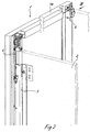
- FIG. 1 a cupboard 1 is shown, which is equipped with a vertically movable sliding door element 2.
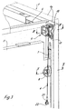
- This sliding door element 2 is, as is apparent from the Figures 2 and 3 results, connected to a known guide means 3 and coupled via a cable 4 with a arranged in the rear region of the cabinet furniture 1 counterweight 5.
- the cable 4 is deflected in the rear region of the cabinet furniture 1 via a erfmdungswashen pulley holder 6 from a horizontal course in a vertical course.
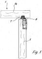
- the counterweight 5 is how out of the Figures 3 and 5 shows particularly clearly, guided within guide channels 7, which are provided in the rear region of the side walls 1a of the cabinet furniture 1, via guide elements 8 engaging in these guide channels.
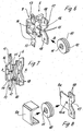
- the pulley holder 6 is - especially the FIGS. 6, 7 and FIGS. 9a to 9c show a bearing part 9 and a cable pulley 10 with a rotation axis 11.
- the pulley 10 is rotatably supported within the bearing part 9 about its axis of rotation 11.
- the bearing part 9 is formed around a perpendicular to the mounting plane of the bearing part (ie resting in the assembled state of the pulley holder on a side wall 1a of a cabinet furniture 1 plane lying) axis of rotation 11 of the pulley 10 in the longitudinal direction intersecting plane AA mirror-symmetrical.
- the bearing member 9 is designed so that the pulley 10 on both sides of the plane of symmetry AA a free has accessible Seilumschlingungsabexcellent of 90 °.
- the rope of a cable 4 can be easily inserted into a circumferential groove 12 of the pulley 10.
- the bearing part 9 is provided with on both sides of the axis of symmetry AA circlips 13, which are integrally connected in an advantageous manner via film hinges 14 with the bearing part and after the assembly of the pulley holder 6 and placing the cable 4 are pivoted in one of the pulley 10 immediately opposite securing position and secured there. It is depending on the used Seilumschlingungsabexcellent one of the securing bracket 13 without function.
- securing brackets 13 As an alternative to the integrally formed on the bearing part 9 securing brackets 13, such securing bracket can be used, which can be formed as separate components and can be clipped to their total operating position on the bearing part 9.
- the bearing part 9 is made in one piece and the pulley 10 can with its axis of rotation 11 in the direction of arrow B in FIG. 6 inserted through insertion slots 15 in the bearing part 9 and clipped into a Achslagerage 16.
- the bearing part consists of two bearing halves 9a and 9b, which are latched together in the longitudinal direction of the axis of rotation 11 of the pulley 10, wherein the axis of rotation 11 is received within corresponding bearing bores 16a of the two bearing halves 9a and 9b.
- the bearing part 9 is provided in the embodiments shown with a Anschraubflansch 17 with through holes 18 for mounting screws 19, by means of which the bearing part 9 on a side wall 1a of a cabinet furniture can be fastened.
- the mounting flange 17 may also be provided with protruding, integrally formed dowel pins which are pressed into a corresponding bore of a furniture side wall 1a.
- the bearing part 9 is still provided in the direction of a furniture side wall 1a projecting fixing lugs 20 which position fixation engage in a recess, provided for holes in a furniture side wall 1a or in an extension of the already existing guide channels 7.
- fixing lugs 20 which position fixation engage in a recess, provided for holes in a furniture side wall 1a or in an extension of the already existing guide channels 7.
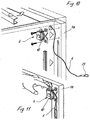
- FIGS. 10 and 11 the assembly steps for fixing a pulley holder 6 on a furniture side wall and for the application of a cable to the pulley 10 are shown vividly.
- the two FIGS. 10 and 11 make clear that a cable 4 after installation of the pulley holder 6 can also be easily placed on the pulley 10 when the cable is provided at the end with an eyelet 21 which serves for connection to a fastened to a counterweight 5 pin 22 ( please refer FIG. 3 ).
- the bearing part 9 is advantageously as well as the pulley 10 made of plastic, the axis of rotation 11 of the pulley 10 is advantageously made of metal.
Landscapes
- Engineering & Computer Science (AREA)
- Mechanical Engineering (AREA)
- Pulleys (AREA)
- Storage Of Web-Like Or Filamentary Materials (AREA)
- Seats For Vehicles (AREA)
- Closing And Opening Devices For Wings, And Checks For Wings (AREA)
Description
- Die vorliegende Erfindung betrifft einen Seilrollenhalter zur Umlenkung von Seilzügen bei vertikal oder horizontal beweglichen Schiebetürelementen von Schrankmöbeln, umfassend ein möbelseitig festlegbares Lagerteil und eine in diesem drehbar gelagerte Seilrolle, wobei das Lagerteil um eine die lotrecht zur Befestigungsebene des Lagerteils verlaufende Drehachse der Seilrolle in Längsrichtung schneidende Ebene A-A spiegelsymmetrisch ausgebildet ist.
- Seilrollenhalter der gattungsgemäßen Art sind beispielsweise aus der
US 5 331 765 A bekannt. - Der vorliegenden Erfindung liegt die Aufgabe zugrunde, einen Seilrollenhalter der gattungsgemäßen Art so zu gestalten, dass dieser für alle Einbauarten uneingeschränkt verwendbar ist.
- Diese Aufgabe wird erfindungsgemäß dadurch gelöst, dass die Seilrolle zu beiden Seiten der Symmetrieebene A-A einen frei zugänglichen Seilumschlingungsabschnitt von jeweils 90° aufweist und dass am Lagerteil zu beiden Seiten der Symmetrieebene liegende Sicherungsbügel für einen auf der Seilrolle geführten Seilzugabschnitt vorgesehen sind und die Sicherungsbügel einstückig über Filmscharniere schwenkbar mit dem Lagerteil verbunden oder als separate Bauteile ausgebildet und lösbar am Lagerteil festgelegt sind.
- Hierdurch kann der Seilzug im Bereich des jeweils benutzten Seilumschlingungsabschnittes von einem der Sicherungsbügel gesichert werden, während der jeweils andere Sicherungsbügel ohne Funktion ist.
- Somit kann auf bequeme Art und Weise ein Seilrollenhalter verwirklicht werden, der für alle Einbauarten uneingeschränkt verwendbar ist.
- Weitere Merkmale der Erfindung sind Gegenstand von Unteransprüchen.
- Ausführungsbeispiele der Erfindung sind in den beigefügten Zeichnungen dargestellt und werden im Folgenden näher beschrieben. Es zeigen:
- Figur 1
- eine perspektivische Darstellung eines Schrankmöbels mit einem Schiebetürelement,
- Figur 2
- eine perspektivische Teildarstellung des oberen, linken Seitenwandbereiches des Schrankmöbels gemäß
Figur 1 mit im Bereich der Rückseite des Schrankmöbels angeordneten, erfindungsgemäßen Seilrollenhalter, - Figur 3
- eine rückseitige Perspektivdarstellung des Schrankmöbels im Sinne des Pfeiles III in
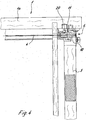
Figur 2 , - Figur 4
- einen Schnitt nach der Linie IV-IV in
Figur 3 , - Figur 5
- einen Schnitt nach der Linie V-V in
Figur 3 , - Figur 6
- eine perspektivische Darstellung eines Seilrollenhalters gemäß vorliegender Erfindung vor der Montage seiner Einzelteile,
- Figur 7
- eine perspektivische Darstellung des Seilrollenhalters nach
Figur 6 im montierten Zustand, - Figur 8
- eine perspektivische Darstellung eines Seilrollenhalters nach einem weiteren Ausführungsbeispiel der Erfindung, gezeigt vor der Montage seiner Einzelteile,
- Figur 9a bis 9c
- verschiedene Ansichten des Seilrollenhalters gemäß
Figur 7 , - Figur 10
- eine der
Figur 3 entsprechende Perspektivdarstellung vor der Montage des Seilrollenhalters, - Figur 11
- eine der
Figur 10 Perspektivdarstellung nach erfolgter Montage des Seilrollenhalters. - In
Figur 1 ist ein Schrankmöbel 1 dargestellt, welches mit einem vertikal verfahrbaren Schiebetürelement 2 ausgestattet ist. - Dieses Schiebetürelement 2 ist, wie sich aus den
Figuren 2 und3 ergibt, mit einer an sich bekannten Führungseinrichtung 3 verbunden und über einen Seilzug 4 mit einem im rückseitigen Bereich des Schrankmöbels 1 angeordneten Gegengewicht 5 gekoppelt. Der Seilzug 4 ist im rückwärtigen Bereich des Schrankmöbels 1 über einen erfmdungsgemäßen Seilrollenhalter 6 aus einem horizontalen Verlauf in einen vertikalen Verlauf umgelenkt. - Das Gegengewicht 5 ist, wie aus den
Figuren 3 und5 besonders deutlich hervorgeht, innerhalb von Führungskanälen 7 geführt, welche im rückwärtigen Bereich der Seitenwände 1a des Schrankmöbels 1 vorgesehen sind, und zwar über in diese Führungskanäle 7 eingreifende Führungselemente 8. - Der Seilrollenhalter 6 besteht - wie besonders die
Figuren 6, 7 sowie 9a bis 9c zeigen - aus einem Lagerteil 9 und einer Seilrolle 10 mit einer Drehachse 11. - Die Seilrolle 10 ist innerhalb des Lagerteils 9 um ihre Drehachse 11 drehbar gelagert.
- Das Lagerteil 9 ist um eine die lotrecht zur Befestigungsebene des Lagerteils (d.h. die im montierten Zustand des Seilrollenhalters auf einer Seitenwand 1a eines Schrankmöbels 1 aufliegende Ebene) liegende Drehachse 11 der Seilrolle 10 in Längsrichtung schneidenden Ebene A-A spiegelsymmetrisch ausgebildet. Dabei ist das Lagerteil 9 so gestaltet, daß die Seilrolle 10 zu beiden Seiten der Symmetrieebene A-A einen frei zugänglichen Seilumschlingungsabschnitt von jeweils 90° aufweist. Somit kann das Seil eines Seilzuges 4 problemlos in eine umfängliche Nut 12 der Seilrolle 10 eingelegt werden.
- Um ein Herausspringen des besagten Seiles aus dieser Nut 12 im Betrieb zu vermeiden, ist das Lagerteil 9 mit zu beiden Seiten der Symmetrieachse A-A liegenden Sicherungsbügeln 13 versehen, welche in vorteilhafter Weise über Filmscharniere 14 mit dem Lagerteil einstückig verbunden sind und nach erfolgter Montage des Seilrollenhalters 6 und Auflegen des Seilzuges 4 in eine der Seilrolle 10 unmittelbar gegenüberliegende Sicherungsposition verschwenkt und dort gesichert werden. Dabei ist je nach den benutzten Seilumschlingungsabschnitt einer der Sicherungsbügel 13 ohne Funktion.
- Alternativ zu den einstückig an das Lagerteil 9 angeformten Sicherungsbügeln 13 können auch solche Sicherungsbügel verwendet werden, die als separate Bauteile ausgebildet und insgesamt in ihre Funktionsstellung auf das Lagerteil 9 aufgeklipst werden können.
- Bei dem bislang beschriebenen Ausführungsbeispiel ist das Lagerteil 9 insgesamt einstückig gefertigt und die Seilrolle 10 kann mit ihrer Drehachse 11 im Sinne des Pfeiles B in
Figur 6 durch Einführschlitze 15 in das Lagerteil 9 eingeführt und in eine Achslageraufnahme 16 eingeklipst werden. - Eine alternative konstruktive Lösung für die Gestaltung des Lagerteils 9 zeigt die Figur 8.
- Hier besteht das Lagerteil aus zwei Lagerteilhälften 9a und 9b, die in Längsrichtung der Drehachse 11 der Seilrolle 10 miteinander verrastbar sind, wobei die Drehachse 11 innerhalb entsprechender Lagerbohrungen 16a der beiden Lagerteilhälften 9a und 9b aufgenommen ist.
- Das Lagerteil 9 ist in den gezeigten Ausführungsbeispielen mit einem Anschraubflansch 17 mit Durchtrittsbohrungen 18 für Befestigungsschrauben 19 versehen, mittels derer das Lagerteil 9 an einer Seitenwand 1a eines Schrankmöbels befestigbar ist. Alternativ hierzu kann der Befestigungsflansch 17 auch mit vorstehenden, einstückig angeformten Dübelzapfen versehen sein, die in eine entsprechende Bohrung einer Möbelseitenwand 1a einpreßbar sind.
- In einem Abstand zu den Durchgangsbohrungen 18 ist das Lagerteil 9 noch mit in Richtung einer Möbelseitenwand 1a vorstehenden Fixierungsnasen 20 versehen, welche lagefixierend in eine Aussparung, in dafür vorgesehene Bohrungen einer Möbelseitenwand 1a oder in eine Verlängerung der ohnehin vorhandenen Führungskanäle 7 eingreifen. Hierdurch wird eine hochbelastbare Verbindung zur Möbelseitenwand 1a gesichert, da die Fixierungsnasen 20 natürlich auch Kräfte aufnehmen und die Befestigungsschrauben 19 und/oder die Dübelzapfen des Lagerteils entlasten können.
- In den
Figuren 10 und 11 sind die Montageschritte zur Festlegung eines Seilrollenhalters 6 an einer Möbelseitenwand und zur Auflegung eines Seilzuges auf die Seilrolle 10 anschaulich dargestellt. Die beidenFiguren 10 und 11 machen deutlich, daß ein Seilzug 4 nach erfolgter Montage des Seilrollenhalters 6 auch dann problemlos auf die Seilrolle 10 aufgelegt werden kann, wenn der Seilzug endseitig mit einer Öse 21 versehen ist, die zur Verbindung mit einem beispielsweise an einem Gegengewicht 5 befestigten Zapfen 22 dient (sieheFigur 3 ). - Das Lagerteil 9 ist vorteilhafterweise ebenso wie die Seilrolle 10 aus Kunststoff hergestellt, die Drehachse 11 der Seilrolle 10 besteht vorteilhafterweise aus Metall.
Claims (7)
- Seilrollenhalter (6) zur Umlenkung von Seilzügen (4) bei vertikal oder horizontal beweglichen Schiebetürelementen (2) von Schrankmöbeln (1), umfassend ein möbelseitig festlegbares Lagerteil (9) und eine in diesem drehbar gelagerte Seilrolle (10), wobei das Lagerteil (9) um eine die lotrecht zur Befestigungsebene des Lagerteils (9) verlaufende Drehachse (11) der Seilrolle (10) in Längsrichtung schneidende Ebene A-A spiegelsymmetrisch ausgebildet ist, dadurch gekennzeichnet, daß die Seilrolle (10) zu beiden Seiten der Symmetrieebene A-A einen frei zugänglichen Seilumschlingungsabschnitt von jeweils 90° aufweist und am Lagerteil (9) zu beiden Seiten der Symmetrieebene A-A liegende Sicherungsbügel (13) für einen auf der Seilrolle (10) geführten Seilzugabschnitt vorgesehen sind und die Sicherungsbügel (13) einstückig über Filmscharniere (14) schwenkbar mit dem Lagerteil (9) verbunden oder als separate Bauteile ausgebildet und lösbar am Lagerteil (9) festgelegt sind wobei die Sicherungsbügel (13) insgesamt in ihre Funktionsstellung auf das Lagerteil (9) aufgeklipst werden können.
- Seilrollenhalter nach Anspruch 1, dadurch gekennzeichnet, daß das Lagerteil (9) einstückig ausgebildet ist.
- Seilrollenhalter nach Anspruch 1 oder 2, dadurch gekennzeichnet, daß das Lagerteil (9) aus zwei Lagerteilhälften (9a und 9b) besteht, die in Achsrichtung der Drehachse (11) vorzugsweise rastend miteinander verbunden sind.
- Seilrollenhalter nach einem der vorhergehenden Ansprüche, dadurch gekennzeichnet, daß das Lagerteil (9) einen Befestigungsflansch (17) mit Durchgangsbohrungen (18) für Befestigungsschrauben (19) und/oder vorstehend angeformte Dübelzapfen zur Festlegung an einer Möbelseitenwand (1a) eines Schrankmöbels aufweist.
- Seilrollenhalter nach einem der vorhergehenden Ansprüche, dadurch gekennzeichnet, daß das Lagerteil (9) in einem Abstand zu den Durchgangsbohrungen (18) und/oder den Dübelzapfen mit über die Befestigungsebene hinaus vorstehenden Fixierungsnasen (20) ausgestattet ist.
- Seilrollenhalter nach einem der vorhergehenden Ansprüche, dadurch gekennzeichnet, daß das Lagerteil (9) und die Seilrolle (10) aus Kunststoff hergestellt sind.
- Seilrollenhalter nach einem der vorhergehenden Ansprüche, dadurch gekennzeichnet, daß die Drehachse (11) der Seilrolle (10) aus Metall hergestellt ist.
Applications Claiming Priority (1)
| Application Number | Priority Date | Filing Date | Title |
|---|---|---|---|
| DE202004010584U DE202004010584U1 (de) | 2004-07-05 | 2004-07-05 | Seilrollenhalter |
Publications (3)
| Publication Number | Publication Date |
|---|---|
| EP1614845A2 EP1614845A2 (de) | 2006-01-11 |
| EP1614845A3 EP1614845A3 (de) | 2013-01-23 |
| EP1614845B1 true EP1614845B1 (de) | 2016-05-18 |
Family
ID=32946783
Family Applications (1)
| Application Number | Title | Priority Date | Filing Date |
|---|---|---|---|
| EP05104044.2A Expired - Lifetime EP1614845B1 (de) | 2004-07-05 | 2005-05-13 | Seilrollenhalter |
Country Status (3)
| Country | Link |
|---|---|
| EP (1) | EP1614845B1 (de) |
| DE (1) | DE202004010584U1 (de) |
| ES (1) | ES2579403T3 (de) |
Families Citing this family (1)
| Publication number | Priority date | Publication date | Assignee | Title |
|---|---|---|---|---|
| DE102006021234A1 (de) * | 2006-05-06 | 2007-11-08 | Kb Knecht Gmbh | Vertikale Schiebetür |
Family Cites Families (6)
| Publication number | Priority date | Publication date | Assignee | Title |
|---|---|---|---|---|
| GB202169A (en) * | 1922-08-21 | 1923-08-16 | Branford Brothers Ltd | Improvements relating to pulleys for sliding sashes and the like |
| GB473775A (en) * | 1936-05-20 | 1937-10-20 | James Douglas Brown | Improvements in and relating to grip devices for the cords of window-sashes |
| DE3201098C2 (de) * | 1982-01-15 | 1986-10-09 | Brose Fahrzeugteile GmbH & Co KG, 8630 Coburg | Seil-Fensterheber, insbesondere für Kraftfahrzeuge |
| US5331765A (en) * | 1992-11-02 | 1994-07-26 | Les Produits Abp, Inc. | Adjusting device for a double-hung sash assembly, improved assembly so obtained and method of use |
| DE19705054C2 (de) * | 1997-01-30 | 2003-02-27 | Brose Fahrzeugteile | Führungsschiene für Kraftfahrzeugfensterheber |
| FR2811008B1 (fr) * | 2000-07-03 | 2003-02-14 | Meritor Light Vehicle Sys Ltd | Systeme d'assemblage d'un element mobile dans un logement |
-
2004
- 2004-07-05 DE DE202004010584U patent/DE202004010584U1/de not_active Expired - Lifetime
-
2005
- 2005-05-13 ES ES05104044.2T patent/ES2579403T3/es not_active Expired - Lifetime
- 2005-05-13 EP EP05104044.2A patent/EP1614845B1/de not_active Expired - Lifetime
Also Published As
| Publication number | Publication date |
|---|---|
| ES2579403T3 (es) | 2016-08-11 |
| EP1614845A2 (de) | 2006-01-11 |
| EP1614845A3 (de) | 2013-01-23 |
| DE202004010584U1 (de) | 2004-09-02 |
Similar Documents
| Publication | Publication Date | Title |
|---|---|---|
| DE102014211846B4 (de) | Kettenspannvorrichtung | |
| EP2059145B1 (de) | Schubkasten | |
| DE69117898T2 (de) | Vorrichtung zum Öffnen und Schliessen eines Deckels | |
| EP2445376B1 (de) | Selbsteinzugsvorrichtung und auszugsführung | |
| DE102007017286A1 (de) | Leitungsführungseinrichtung | |
| EP3622153B1 (de) | Möbelantrieb | |
| DE102010037905A1 (de) | Verriegelungsanordnung | |
| EP2362050A2 (de) | Scharniervorrichtung, Haushaltsgerät mit einer Tür und Verfahren zum Nachrüsten eines Dämpfers | |
| DE3942383C2 (de) | Spannvorrichtung | |
| EP3832062A1 (de) | Antriebseinheit für eine schiebeanordnung, insbesondere schiebetür | |
| EP3472414B1 (de) | Kraftfahrzeug-griffanordnung | |
| DE102009020994B4 (de) | Einzugvorrichtung | |
| EP2581666B1 (de) | Tür für ein Haushaltsgerät, Haushaltsgerät mit einer Tür und Verfahren zum Bewegen eines Griffs einer Tür eines Haushaltsgeräts | |
| EP3758553B1 (de) | Möbel oder haushaltsgerät und verfahren zur montage einer funktionseinheit eines schubelements in einem möbel oder haushaltsgerät | |
| EP0274552B1 (de) | Aussen sichtbares 180-Grad-Scharnier | |
| EP1614845B1 (de) | Seilrollenhalter | |
| EP0930413A1 (de) | Seilumlenkung für seilbetätige Fensterheber | |
| EP3368734B1 (de) | Führungsanordnung für schiebetüren und schrankmöbel | |
| DE2422477A1 (de) | Auszieh-haltevorrichtung fuer einschubgeraete | |
| DE60301773T9 (de) | Verfahren und Gerät für die Montage eines Haushaltgeräts in einem Schrank | |
| DE7530970U (de) | Haltevorrichtung fuer abdeck-gitterroste | |
| DE3732892C2 (de) | ||
| DE3219709C2 (de) | ||
| EP0359857A1 (de) | Scharnierstift | |
| DE29712027U1 (de) | Schaltschrank für die Elektronik und Elektrotechnik |
Legal Events
| Date | Code | Title | Description |
|---|---|---|---|
| PUAI | Public reference made under article 153(3) epc to a published international application that has entered the european phase |
Free format text: ORIGINAL CODE: 0009012 |
|
| AK | Designated contracting states |
Kind code of ref document: A2 Designated state(s): AT BE BG CH CY CZ DE DK EE ES FI FR GB GR HU IE IS IT LI LT LU MC NL PL PT RO SE SI SK TR |
|
| AX | Request for extension of the european patent |
Extension state: AL BA HR LV MK YU |
|
| PUAL | Search report despatched |
Free format text: ORIGINAL CODE: 0009013 |
|
| AK | Designated contracting states |
Kind code of ref document: A3 Designated state(s): AT BE BG CH CY CZ DE DK EE ES FI FR GB GR HU IE IS IT LI LT LU MC NL PL PT RO SE SI SK TR |
|
| AX | Request for extension of the european patent |
Extension state: AL BA HR LV MK YU |
|
| 17P | Request for examination filed |
Effective date: 20130625 |
|
| RBV | Designated contracting states (corrected) |
Designated state(s): AT BE BG CH CY CZ DE DK EE ES FI FR GB GR HU IE IS IT LI LT LU MC NL PL PT RO SE SI SK TR |
|
| 17Q | First examination report despatched |
Effective date: 20130821 |
|
| AKX | Designation fees paid |
Designated state(s): AT BE BG CH CY CZ DE DK EE ES FI FR GB GR HU IE IS IT LI LT LU MC NL PL PT RO SE SI SK TR |
|
| GRAP | Despatch of communication of intention to grant a patent |
Free format text: ORIGINAL CODE: EPIDOSNIGR1 |
|
| RIC1 | Information provided on ipc code assigned before grant |
Ipc: E05D 13/00 20060101ALI20151130BHEP Ipc: E05F 11/48 20060101AFI20151130BHEP |
|
| INTG | Intention to grant announced |
Effective date: 20160105 |
|
| RAP1 | Party data changed (applicant data changed or rights of an application transferred) |
Owner name: HETTICH-HEINZE GMBH & CO. KG |
|
| GRAS | Grant fee paid |
Free format text: ORIGINAL CODE: EPIDOSNIGR3 |
|
| GRAA | (expected) grant |
Free format text: ORIGINAL CODE: 0009210 |
|
| AK | Designated contracting states |
Kind code of ref document: B1 Designated state(s): AT BE BG CH CY CZ DE DK EE ES FI FR GB GR HU IE IS IT LI LT LU MC NL PL PT RO SE SI SK TR |
|
| REG | Reference to a national code |
Ref country code: GB Ref legal event code: FG4D Free format text: NOT ENGLISH |
|
| REG | Reference to a national code |
Ref country code: CH Ref legal event code: EP |
|
| REG | Reference to a national code |
Ref country code: IE Ref legal event code: FG4D Free format text: LANGUAGE OF EP DOCUMENT: GERMAN Ref country code: CH Ref legal event code: NV Representative=s name: ISLER AND PEDRAZZINI AG, CH Ref country code: AT Ref legal event code: REF Ref document number: 800641 Country of ref document: AT Kind code of ref document: T Effective date: 20160615 |
|
| REG | Reference to a national code |
Ref country code: DE Ref legal event code: R096 Ref document number: 502005015229 Country of ref document: DE |
|
| REG | Reference to a national code |
Ref country code: ES Ref legal event code: FG2A Ref document number: 2579403 Country of ref document: ES Kind code of ref document: T3 Effective date: 20160811 |
|
| REG | Reference to a national code |
Ref country code: NL Ref legal event code: MP Effective date: 20160518 |
|
| REG | Reference to a national code |
Ref country code: LT Ref legal event code: MG4D |
|
| PG25 | Lapsed in a contracting state [announced via postgrant information from national office to epo] |
Ref country code: LT Free format text: LAPSE BECAUSE OF FAILURE TO SUBMIT A TRANSLATION OF THE DESCRIPTION OR TO PAY THE FEE WITHIN THE PRESCRIBED TIME-LIMIT Effective date: 20160518 Ref country code: FI Free format text: LAPSE BECAUSE OF FAILURE TO SUBMIT A TRANSLATION OF THE DESCRIPTION OR TO PAY THE FEE WITHIN THE PRESCRIBED TIME-LIMIT Effective date: 20160518 Ref country code: NL Free format text: LAPSE BECAUSE OF FAILURE TO SUBMIT A TRANSLATION OF THE DESCRIPTION OR TO PAY THE FEE WITHIN THE PRESCRIBED TIME-LIMIT Effective date: 20160518 |
|
| PG25 | Lapsed in a contracting state [announced via postgrant information from national office to epo] |
Ref country code: PT Free format text: LAPSE BECAUSE OF FAILURE TO SUBMIT A TRANSLATION OF THE DESCRIPTION OR TO PAY THE FEE WITHIN THE PRESCRIBED TIME-LIMIT Effective date: 20160919 Ref country code: SE Free format text: LAPSE BECAUSE OF FAILURE TO SUBMIT A TRANSLATION OF THE DESCRIPTION OR TO PAY THE FEE WITHIN THE PRESCRIBED TIME-LIMIT Effective date: 20160518 Ref country code: GR Free format text: LAPSE BECAUSE OF FAILURE TO SUBMIT A TRANSLATION OF THE DESCRIPTION OR TO PAY THE FEE WITHIN THE PRESCRIBED TIME-LIMIT Effective date: 20160819 |
|
| PG25 | Lapsed in a contracting state [announced via postgrant information from national office to epo] |
Ref country code: EE Free format text: LAPSE BECAUSE OF FAILURE TO SUBMIT A TRANSLATION OF THE DESCRIPTION OR TO PAY THE FEE WITHIN THE PRESCRIBED TIME-LIMIT Effective date: 20160518 Ref country code: DK Free format text: LAPSE BECAUSE OF FAILURE TO SUBMIT A TRANSLATION OF THE DESCRIPTION OR TO PAY THE FEE WITHIN THE PRESCRIBED TIME-LIMIT Effective date: 20160518 Ref country code: CZ Free format text: LAPSE BECAUSE OF FAILURE TO SUBMIT A TRANSLATION OF THE DESCRIPTION OR TO PAY THE FEE WITHIN THE PRESCRIBED TIME-LIMIT Effective date: 20160518 Ref country code: RO Free format text: LAPSE BECAUSE OF FAILURE TO SUBMIT A TRANSLATION OF THE DESCRIPTION OR TO PAY THE FEE WITHIN THE PRESCRIBED TIME-LIMIT Effective date: 20160518 Ref country code: SK Free format text: LAPSE BECAUSE OF FAILURE TO SUBMIT A TRANSLATION OF THE DESCRIPTION OR TO PAY THE FEE WITHIN THE PRESCRIBED TIME-LIMIT Effective date: 20160518 |
|
| REG | Reference to a national code |
Ref country code: DE Ref legal event code: R097 Ref document number: 502005015229 Country of ref document: DE |
|
| PG25 | Lapsed in a contracting state [announced via postgrant information from national office to epo] |
Ref country code: PL Free format text: LAPSE BECAUSE OF FAILURE TO SUBMIT A TRANSLATION OF THE DESCRIPTION OR TO PAY THE FEE WITHIN THE PRESCRIBED TIME-LIMIT Effective date: 20160518 |
|
| PLBE | No opposition filed within time limit |
Free format text: ORIGINAL CODE: 0009261 |
|
| STAA | Information on the status of an ep patent application or granted ep patent |
Free format text: STATUS: NO OPPOSITION FILED WITHIN TIME LIMIT |
|
| 26N | No opposition filed |
Effective date: 20170221 |
|
| PG25 | Lapsed in a contracting state [announced via postgrant information from national office to epo] |
Ref country code: SI Free format text: LAPSE BECAUSE OF FAILURE TO SUBMIT A TRANSLATION OF THE DESCRIPTION OR TO PAY THE FEE WITHIN THE PRESCRIBED TIME-LIMIT Effective date: 20160518 |
|
| PG25 | Lapsed in a contracting state [announced via postgrant information from national office to epo] |
Ref country code: LU Free format text: LAPSE BECAUSE OF NON-PAYMENT OF DUE FEES Effective date: 20170531 |
|
| GBPC | Gb: european patent ceased through non-payment of renewal fee |
Effective date: 20170513 |
|
| PG25 | Lapsed in a contracting state [announced via postgrant information from national office to epo] |
Ref country code: MC Free format text: LAPSE BECAUSE OF FAILURE TO SUBMIT A TRANSLATION OF THE DESCRIPTION OR TO PAY THE FEE WITHIN THE PRESCRIBED TIME-LIMIT Effective date: 20160518 |
|
| REG | Reference to a national code |
Ref country code: IE Ref legal event code: MM4A |
|
| REG | Reference to a national code |
Ref country code: ES Ref legal event code: GC2A Effective date: 20180216 |
|
| REG | Reference to a national code |
Ref country code: FR Ref legal event code: ST Effective date: 20180131 |
|
| PG25 | Lapsed in a contracting state [announced via postgrant information from national office to epo] |
Ref country code: LU Free format text: LAPSE BECAUSE OF NON-PAYMENT OF DUE FEES Effective date: 20170513 |
|
| REG | Reference to a national code |
Ref country code: DE Ref legal event code: R084 Ref document number: 502005015229 Country of ref document: DE |
|
| REG | Reference to a national code |
Ref country code: BE Ref legal event code: MM Effective date: 20170531 |
|
| PG25 | Lapsed in a contracting state [announced via postgrant information from national office to epo] |
Ref country code: GB Free format text: LAPSE BECAUSE OF NON-PAYMENT OF DUE FEES Effective date: 20170513 Ref country code: IE Free format text: LAPSE BECAUSE OF NON-PAYMENT OF DUE FEES Effective date: 20170513 |
|
| PG25 | Lapsed in a contracting state [announced via postgrant information from national office to epo] |
Ref country code: FR Free format text: LAPSE BECAUSE OF NON-PAYMENT OF DUE FEES Effective date: 20170531 |
|
| REG | Reference to a national code |
Ref country code: AT Ref legal event code: MM01 Ref document number: 800641 Country of ref document: AT Kind code of ref document: T Effective date: 20170513 |
|
| PG25 | Lapsed in a contracting state [announced via postgrant information from national office to epo] |
Ref country code: BE Free format text: LAPSE BECAUSE OF NON-PAYMENT OF DUE FEES Effective date: 20170531 Ref country code: AT Free format text: LAPSE BECAUSE OF NON-PAYMENT OF DUE FEES Effective date: 20170513 |
|
| PG25 | Lapsed in a contracting state [announced via postgrant information from national office to epo] |
Ref country code: HU Free format text: LAPSE BECAUSE OF FAILURE TO SUBMIT A TRANSLATION OF THE DESCRIPTION OR TO PAY THE FEE WITHIN THE PRESCRIBED TIME-LIMIT; INVALID AB INITIO Effective date: 20050513 |
|
| PG25 | Lapsed in a contracting state [announced via postgrant information from national office to epo] |
Ref country code: BG Free format text: LAPSE BECAUSE OF FAILURE TO SUBMIT A TRANSLATION OF THE DESCRIPTION OR TO PAY THE FEE WITHIN THE PRESCRIBED TIME-LIMIT Effective date: 20160518 |
|
| PG25 | Lapsed in a contracting state [announced via postgrant information from national office to epo] |
Ref country code: CY Free format text: LAPSE BECAUSE OF NON-PAYMENT OF DUE FEES Effective date: 20160518 |
|
| PG25 | Lapsed in a contracting state [announced via postgrant information from national office to epo] |
Ref country code: IS Free format text: LAPSE BECAUSE OF FAILURE TO SUBMIT A TRANSLATION OF THE DESCRIPTION OR TO PAY THE FEE WITHIN THE PRESCRIBED TIME-LIMIT Effective date: 20160918 |
|
| PGFP | Annual fee paid to national office [announced via postgrant information from national office to epo] |
Ref country code: ES Payment date: 20210618 Year of fee payment: 17 |
|
| P01 | Opt-out of the competence of the unified patent court (upc) registered |
Effective date: 20230403 |
|
| REG | Reference to a national code |
Ref country code: ES Ref legal event code: FD2A Effective date: 20230628 |
|
| PG25 | Lapsed in a contracting state [announced via postgrant information from national office to epo] |
Ref country code: ES Free format text: LAPSE BECAUSE OF NON-PAYMENT OF DUE FEES Effective date: 20220514 |
|
| PGFP | Annual fee paid to national office [announced via postgrant information from national office to epo] |
Ref country code: TR Payment date: 20230509 Year of fee payment: 19 |
|
| PGFP | Annual fee paid to national office [announced via postgrant information from national office to epo] |
Ref country code: DE Payment date: 20240517 Year of fee payment: 20 |
|
| PGFP | Annual fee paid to national office [announced via postgrant information from national office to epo] |
Ref country code: CH Payment date: 20240602 Year of fee payment: 20 |
|
| PGFP | Annual fee paid to national office [announced via postgrant information from national office to epo] |
Ref country code: IT Payment date: 20240531 Year of fee payment: 20 |
|
| REG | Reference to a national code |
Ref country code: DE Ref legal event code: R071 Ref document number: 502005015229 Country of ref document: DE |
|
| REG | Reference to a national code |
Ref country code: CH Ref legal event code: PL |