EP1614480B1 - Robot d'application à cinématique parallèle - Google Patents
Robot d'application à cinématique parallèle Download PDFInfo
- Publication number
- EP1614480B1 EP1614480B1 EP05106073A EP05106073A EP1614480B1 EP 1614480 B1 EP1614480 B1 EP 1614480B1 EP 05106073 A EP05106073 A EP 05106073A EP 05106073 A EP05106073 A EP 05106073A EP 1614480 B1 EP1614480 B1 EP 1614480B1
- Authority
- EP
- European Patent Office
- Prior art keywords
- robot
- application
- painting
- kinematic
- parallel
- Prior art date
- Legal status (The legal status is an assumption and is not a legal conclusion. Google has not performed a legal analysis and makes no representation as to the accuracy of the status listed.)
- Expired - Lifetime
Links
Images



Classifications
-
- B—PERFORMING OPERATIONS; TRANSPORTING
- B25—HAND TOOLS; PORTABLE POWER-DRIVEN TOOLS; MANIPULATORS
- B25J—MANIPULATORS; CHAMBERS PROVIDED WITH MANIPULATION DEVICES
- B25J17/00—Joints
- B25J17/02—Wrist joints
- B25J17/0258—Two-dimensional joints
- B25J17/0266—Two-dimensional joints comprising more than two actuating or connecting rods
-
- B—PERFORMING OPERATIONS; TRANSPORTING
- B05—SPRAYING OR ATOMISING IN GENERAL; APPLYING FLUENT MATERIALS TO SURFACES, IN GENERAL
- B05B—SPRAYING APPARATUS; ATOMISING APPARATUS; NOZZLES
- B05B13/00—Machines or plants for applying liquids or other fluent materials to surfaces of objects or other work by spraying, not covered by groups B05B1/00 - B05B11/00
- B05B13/02—Means for supporting work; Arrangement or mounting of spray heads; Adaptation or arrangement of means for feeding work
- B05B13/04—Means for supporting work; Arrangement or mounting of spray heads; Adaptation or arrangement of means for feeding work the spray heads being moved during spraying operation
- B05B13/0431—Means for supporting work; Arrangement or mounting of spray heads; Adaptation or arrangement of means for feeding work the spray heads being moved during spraying operation with spray heads moved by robots or articulated arms, e.g. for applying liquid or other fluent material to three-dimensional [3D] surfaces
- B05B13/0433—Means for supporting work; Arrangement or mounting of spray heads; Adaptation or arrangement of means for feeding work the spray heads being moved during spraying operation with spray heads moved by robots or articulated arms, e.g. for applying liquid or other fluent material to three-dimensional [3D] surfaces the work being vehicle components, e.g. vehicle bodies
Definitions
- the invention relates to an application robot for applying a coating agent to an application object, in particular for painting motor vehicle body parts, according to the preamble of claim 1.
- multiaxial painting robots with serial kinematics are known to be used to guide the rotary atomizers used as application devices.
- Such painting robots are for example off DE 100 10 615 A1 known.
- a disadvantage of such multi-axis painting robots for guiding the application devices is the complex mechanism (for example, gearbox, mass compensation element) of the multi-axis painting robots.
- Another disadvantage of conventional multi-axis painting robots is the unfavorable mass ratio between the mass of the application device (in a rotary atomizer about 15 kg) and the robot mass of more than 500 kg, which among other things leads to a high energy consumption in the movement of the large robot mass.
- the document XP002349397 discloses a welding robot with parallel kinematics and connected serial kinematics for use in welding tasks ,
- the document DE 199 52 530 A1 also discloses a robot with a parallel kinematic, which has an additional serial kinematics, this robot being suitable for moving a tool or a workpiece.
- the invention is therefore based on the object to improve the known application robot accordingly.
- the invention comprises the general technical teaching of using an application robot with a parallel kinematics instead of a conventional multi-axis painting robot with a serial kinematics.
- parallel kinematics used in the context of the invention means that the application robot according to the invention has a plurality of drive axes which act in parallel on the end effector to which the application tool (eg a paint spray gun or a rotary atomizer) can be fastened.
- the application tool eg a paint spray gun or a rotary atomizer
- a parallel kinematic as it DE 100 19 162 A1 is known, so that the content of this document of the present description in the design of the parallel kinematic is fully attributable.
- the end effector of the parallel kinematic system is connected to at least one base via a plurality of kinematic members, whereby the individual kinematic members may be, for example, extendable telescopic arms which can be driven, for example, electrically, pneumatically or hydraulically.
- the end effector of the parallel kinematics is guided by three kinematic members, so that the parallel kinematics are also referred to as tripod.
- the invention is not limited to three in terms of the number of kinematic members, but also with four or more kinematic members feasible.
- the base of the kinematic members may optionally be stationary or movable, wherein in a preferred embodiment of the invention, the base of all kinematic members is movable to expand the working space of the application robot according to the invention.
- the base of the kinematic members on at least one travel rail is linearly displaceable.
- the application robot for guiding the application device has a combination of a parallel kinematics and a serial kinematics.
- a robot arm can be mounted rotatably and / or pivotably on the end effector of the parallel kinematics.
- a conventional robot hand axis is attached to the end effector of the parallel kinematics or to the robot arm.
- this is preferably pivotable about an axis of rotation, which preferably runs parallel to the longitudinal axis of the painting line.
- the axis of rotation of the robot arm thus preferably runs parallel to the feed direction of the application objects in the paint shop.
- the application device is guided exclusively by a parallel kinematics.
- An advantage of the inventive structure of the application robot is the lower weight compared to conventional application robots with a serial kinematics. This in turn advantageously enables a suspended mounting of the application robot according to the invention within a painting cell, without the painting cell having to be substantially mechanically reinforced for this purpose.
- the application robot according to the invention can thus have, for example, an overhead mounting.
- the application robot according to the invention is attached laterally to a side wall of the painting cell.
- a conventional floor mounting of the application robot according to the invention is possible.
- the application robot according to the invention preferably has a mass which is substantially smaller than 500 kg, which is of the order of magnitude of conventional application robots with serial kinematics.
- the mass of the application robot according to the invention may be less than 400 kg, 300 kg, 200 kg, 100 kg or even less than 50 kg.
- an application robot used in the context of the invention is not limited to painting robots for painting motor vehicle body parts, but also encompasses other robots in which an application means (eg Primer, filler, basecoat, clearcoat, transport wax) is applied to an application object.
- an application means eg Primer, filler, basecoat, clearcoat, transport wax
- the invention is not limited to a single application robot, but also includes a painting cell with an at least partially closed painting booth and at least one application robot according to the invention, as described above.
- the invention also encompasses a complete coating installation with an application robot according to the invention and the novel use of a robot with parallel kinematics as the application robot in a coating installation.
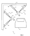
- FIG. 1 show in a greatly simplified form a painting cell 1 of a painting plant for painting automotive body parts, wherein for simplicity, only a motor vehicle body 2 is shown schematically.
- the paint booth 1 is hereby limited by a spray booth 3, wherein in the paint booth 1 on the inner wall of the spray booth 3 above and on the side wall in each case a painting robot 4, 5 is mounted.
- the painting installation has a plurality of linear guides 6, 7, 8 in the form of moving rails, along which the two painting robots 4, 5 can be displaced in the longitudinal direction of the painting line.
- the painting robot 4 has a plurality of extendable telescopic arms 9, 10, 11 as kinematic members, which can be driven, for example, electrically, pneumatically or hydraulically and lead to an end effector 12, to which a rotary atomizer 13 is attached.
- the telescopic arms 9-11 are supported on a respective base 14, 15 and 16, wherein the bases 14-16 along the linear guide 6 are displaceable, as seen from FIG. 2 is apparent.
- the painting robot 4 can be moved in the longitudinal direction of the linear guide 6.
- the end effector 12 can be largely freely positioned within the working space of the painting robot 4, which is a correspondingly allows free guidance of the rotary atomizer 13 to the vehicle body 2.
- the painting robot 5 mounted on the side of the painting booth 3 likewise has a plurality of extendable telescopic arms 17, 18, 19 which can be driven electrically, pneumatically or hydraulically and which are supported on the respective cabin 20, 21, 22.
- the base 20 is in this case displaceably guided in the linear guide 7, while the two bases 21, 22 are guided displaceably in the lower linear guide 8.
- the entire painting robot 5 can be moved in the longitudinal direction of the painting.
- the telescopic arms 17-19 carry a further end effector 23 to which a rotary atomizer 24 is also attached.
- the two painting robots 4, 5 thus each have a parallel kinematics for guiding the end effector 12 or 23, which leads to a more favorable mass ratio between the mass of the application device and the robot mass in comparison to conventional multi-axis painting robots.
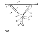
- FIG. 3 illustrated embodiment of a painting robot 4 is largely consistent with the in FIG. 1 shown painting robot 4 match, so that to avoid repetition largely to the above description FIG. 1 is referenced, wherein for corresponding components the same reference numerals as in FIG. 1 be used.
- a special feature of this embodiment is that the rotary atomizer 13 is not attached directly to the end effector 12.
- a robot hand axis 25 with a serial kinematics is attached to the end effector 12, wherein the robot hand axis 25 guides the rotary atomizer 13 to be highly mobile.
- the robot hand axis 25 may be designed to be largely conventional, so that reference is made to the relevant prior art with regard to the construction and the mode of operation of the robot hand axis 25.
- the mechanical control of the robot hand axis 25 is not shown here for the sake of simplicity.
- This embodiment of the painting robot 4 is thus characterized by the combination of a parallel kinematics with a serial kinematics of the robot hand axis 25.
- a special feature of this embodiment is that the robot hand axis 25 and 26 is not attached directly to the end effector 12 and 23, respectively. Instead, a robot arm 27 or 28 is disposed between the end effector 12 or 23 and the robot hand axis 25 or 26, wherein the robot arm 27 is pivotable about a pivot axis 29, while the robot arm 28 is pivotable about a pivot axis 30.
- the two pivot axes 29, 30 extend parallel to the longitudinal axis of the painting line, so that the painting robot 5 at the Side of the paint line can perform a meandering movement, which is advantageous for painting.
Landscapes
- Engineering & Computer Science (AREA)
- Robotics (AREA)
- Mechanical Engineering (AREA)
- Spray Control Apparatus (AREA)
- Manipulator (AREA)
- Forklifts And Lifting Vehicles (AREA)
Claims (12)
- Robot d'application (4, 5) pour l'application d'un agent de revêtement sur un objet d'application comprenant- un effecteur final (12, 23) pour le guidage d'un outil application (13, 24),- une cinématique parallèle pour le guidage mécanique de l'effecteur final (12, 23) avec l'outil d'application (13, 24), et- une combinaison de la cinématique parallèle avec au moins une cinématique série supplémentaire pour le guidage de l'outil d'application (13, 24),caractérisé en ce que- le robot d'application convient pour le laquage de parties de carrosseries automobiles (2), et- un bras de robot (27, 28) guidant l'outil d'application (13, 24) est placé de façon pivotante et/ou rotative et/ou un axe de main de robot (25, 26) est placé sur l'effecteur final (12, 13) de la cinématique parallèle.
- Robot d'application (4, 5) selon la revendication 1, caractérisé en ce que l'effecteur final (12, 23) de la cinématique parallèle est relié par plusieurs éléments (9-11, 17-19) cinématiques à au moins une base (14-16, 20-22).
- Robot d'application (4, 5) selon la revendication 2, caractérisé en ce que les éléments (9-11, 17-19) cinématiques de la cinématique parallèle sont des bras télescopiques déployables, qui sont entraînés de façon électrique, pneumatique ou hydraulique.
- Robot d'application (4, 5) selon la revendication 2 ou 3, caractérisé en ce que la base (14-16, 20-22) des éléments (9-11, 17-19) cinématiques est mobile.
- Robot d'application (4, 5) selon la revendication 4, caractérisé en ce que la base (14-16, 20-22) des éléments (9-11, 17-19) cinématiques peut coulisser linéairement sur au moins un guide linéaire (6-8).
- Robot d'application (4, 5) selon l'une quelconque des revendications précédentes, caractérisé en ce que l'outil d'application (13, 24) est un pistolet de laquage ou un pulvérisateur à rotation.
- Robot d'application (4, 5) selon l'une quelconque des revendications précédentes, caractérisé en ce que l'axe de la main de robot (25, 26) est placé sur le bras de robot (27, 28).
- Robot d'application (4, 5) selon l'une quelconque des revendications précédentes, caractérisé en ce que le bras de robot (27, 28) peut tourner autour d'un axe de rotation (29, 30), qui est agencé sensiblement parallèlement à la direction d'avancement de l'objet d'application (2).
- Robot d'application (4, 5) selon l'une quelconque des revendications précédentes, caractérisé par un montage suspendu au-dessus de la tête ou un montage sur paroi latérale.
- Cellule de laquage comprenant une cabine de laquage (3) au moins en partie fermée et au moins un robot d'application (4, 5) selon l'une quelconque des revendications précédentes.
- Installation de revêtement comprenant au moins un robot d'application (4, 5) selon l'une quelconque des revendications 1 à 9.
- Utilisation d'un robot d'application (4, 5) selon l'une quelconque des revendications 1 à 9 dans une installation de revêtement.
Applications Claiming Priority (1)
| Application Number | Priority Date | Filing Date | Title |
|---|---|---|---|
| DE102004033329A DE102004033329B4 (de) | 2004-07-09 | 2004-07-09 | Applikationsroboter mit einer Parallelkinematik |
Publications (2)
| Publication Number | Publication Date |
|---|---|
| EP1614480A1 EP1614480A1 (fr) | 2006-01-11 |
| EP1614480B1 true EP1614480B1 (fr) | 2008-03-26 |
Family
ID=35056987
Family Applications (1)
| Application Number | Title | Priority Date | Filing Date |
|---|---|---|---|
| EP05106073A Expired - Lifetime EP1614480B1 (fr) | 2004-07-09 | 2005-07-05 | Robot d'application à cinématique parallèle |
Country Status (4)
| Country | Link |
|---|---|
| EP (1) | EP1614480B1 (fr) |
| AT (1) | ATE390209T1 (fr) |
| DE (2) | DE102004033329B4 (fr) |
| ES (1) | ES2303188T3 (fr) |
Cited By (2)
| Publication number | Priority date | Publication date | Assignee | Title |
|---|---|---|---|---|
| DE102008037035A1 (de) | 2008-08-08 | 2010-02-18 | Dürr Systems GmbH | Lackierroboter und zugehöriges Betriebsverfahren |
| DE102021115547A1 (de) | 2021-06-16 | 2022-12-22 | Deutsches Zentrum für Luft- und Raumfahrt e.V. | Robotersystem |
Families Citing this family (18)
| Publication number | Priority date | Publication date | Assignee | Title |
|---|---|---|---|---|
| DE102005033972A1 (de) | 2005-07-20 | 2007-01-25 | Dürr Systems GmbH | Beschichtungsverfahren und zugehörige Beschichtungseinrichtung |
| ITPR20060035A1 (it) * | 2006-04-12 | 2007-10-13 | Turbocoating Spa | Torcia per deposizione di ricoprimenti superficiali mediante tecnologie thermal spray e corrispondenti ricoprimenti. |
| KR101681895B1 (ko) | 2008-03-20 | 2016-12-05 | 듀르 시스템스 게엠베하 | 도장 로봇 및 그 작동방법 |
| JP4659098B2 (ja) * | 2009-02-13 | 2011-03-30 | ファナック株式会社 | 3自由度を有する姿勢変更機構を備えたパラレルリンクロボット |
| US8893578B2 (en) | 2009-02-13 | 2014-11-25 | Fanuc Corporation | Parallel robot provided with wrist section having three degrees of freedom |
| DE102009042014A1 (de) * | 2009-09-21 | 2011-03-24 | Dürr Systems GmbH | Handhabungsvorrichtung |
| DE202010004471U1 (de) * | 2010-04-01 | 2011-08-11 | Emima Gmbh | Werkzeugträgerstruktur für eine Werkzeugmaschine |
| DE102011108215A1 (de) | 2011-07-21 | 2013-01-24 | Daimler Ag | Korrosionsschutz-Verfahren zum Behandeln von Fügebereichen einer Kraftfahrzeugkarosserie |
| WO2014176334A1 (fr) * | 2013-04-23 | 2014-10-30 | Northwestern University | Manipulateurs parallèles translationnels et leurs procédés de fonctionnement |
| DE102013013530A1 (de) * | 2013-08-13 | 2015-03-12 | Dürr Systems GmbH | Applikationssystem mit seilgeführter Handhabungsvorrichtung zum Bewegen eines Applikationsgeräts |
| DE102015009163A1 (de) | 2015-07-14 | 2017-01-19 | Dürr Systems Ag | Beschichtungsanlagenroboter, insbesondere Handhabungsroboter |
| JP2019005863A (ja) * | 2017-06-26 | 2019-01-17 | 山洋電気株式会社 | パラレルリンクロボットシステム |
| CN110733056B (zh) * | 2019-11-01 | 2024-06-18 | 达闼机器人股份有限公司 | 机器人的多轴机械臂及其转接组件、机器人 |
| CN110841840A (zh) * | 2019-11-08 | 2020-02-28 | 江苏科技大学 | 一种用于船舶外板涂装的伸缩式喷涂机器人 |
| CN111185329B (zh) * | 2019-12-30 | 2020-09-01 | 盐城市沿海新能源汽车科技有限公司 | 一种汽车制造用车身喷涂机器人 |
| CN113021303B (zh) * | 2021-03-01 | 2022-08-09 | 清华大学 | 四自由度并联机构及工业机器人 |
| CN113171906B (zh) | 2021-04-27 | 2022-08-05 | 合肥工业大学 | 一种具有大工作空间的可移动式电液复合驱动喷涂机器人 |
| CN116425057A (zh) * | 2023-02-20 | 2023-07-14 | 中国船舶集团有限公司第七一三研究所 | 一种多自由度机械臂 |
Family Cites Families (4)
| Publication number | Priority date | Publication date | Assignee | Title |
|---|---|---|---|---|
| US4435116A (en) * | 1982-05-27 | 1984-03-06 | Deberg Walter H | Robotic manipulator |
| DE19952530A1 (de) * | 1999-10-30 | 2001-05-10 | Hueller Hille Gmbh | Bearbeitungsmaschine zum mehrachsigen Bewegen eines Werkzeuges oder eines Werkstückes |
| DE10010615A1 (de) * | 2000-03-03 | 2001-09-06 | Duerr Systems Gmbh | Roboter zum Beschichten oder Behandeln von Werkstücken |
| DE10019162A1 (de) * | 2000-04-12 | 2001-10-25 | Kai Anding | Bewegungssystem mit Parallelstruktur ("Cylindric-Glide") |
-
2004
- 2004-07-09 DE DE102004033329A patent/DE102004033329B4/de not_active Expired - Fee Related
-
2005
- 2005-07-05 AT AT05106073T patent/ATE390209T1/de not_active IP Right Cessation
- 2005-07-05 DE DE502005003420T patent/DE502005003420D1/de not_active Expired - Lifetime
- 2005-07-05 ES ES05106073T patent/ES2303188T3/es not_active Expired - Lifetime
- 2005-07-05 EP EP05106073A patent/EP1614480B1/fr not_active Expired - Lifetime
Cited By (3)
| Publication number | Priority date | Publication date | Assignee | Title |
|---|---|---|---|---|
| DE102008037035A1 (de) | 2008-08-08 | 2010-02-18 | Dürr Systems GmbH | Lackierroboter und zugehöriges Betriebsverfahren |
| DE102008037035B4 (de) | 2008-08-08 | 2023-05-25 | Dürr Systems Ag | Ventilanordnung eines Lackierroboters |
| DE102021115547A1 (de) | 2021-06-16 | 2022-12-22 | Deutsches Zentrum für Luft- und Raumfahrt e.V. | Robotersystem |
Also Published As
| Publication number | Publication date |
|---|---|
| ATE390209T1 (de) | 2008-04-15 |
| DE502005003420D1 (de) | 2008-05-08 |
| EP1614480A1 (fr) | 2006-01-11 |
| DE102004033329A1 (de) | 2006-02-02 |
| DE102004033329B4 (de) | 2007-08-16 |
| ES2303188T3 (es) | 2008-08-01 |
Similar Documents
| Publication | Publication Date | Title |
|---|---|---|
| EP1614480B1 (fr) | Robot d'application à cinématique parallèle | |
| DE102004033640B4 (de) | Farbauftragssystem | |
| EP2698232B1 (fr) | Dispositif de peinture | |
| DE102010007631B4 (de) | Parallelroboter mit einem Handgelenkabschnitt mit drei Freiheitsgraden | |
| EP1733799B1 (fr) | Robot équipé de plusieurs appareils de pulvérisation | |
| EP3307491B1 (fr) | Robot pour installation de revêtement, en particulier robot manipulateur | |
| EP0812652B1 (fr) | Dispositif pour usiner et/ou monter des pièces | |
| EP2740563A1 (fr) | Dispositif d'usinage, machine d'usinage et procédé de déplacement d'une tête d'usinage | |
| EP0338334B1 (fr) | Machine programmable pour traiter une pièce ayant des contours prédéterminés | |
| DE10391447B4 (de) | Hybrider Parallelmanipulator zum Verfahren eines Arbeitskopfes im Raum | |
| DE102014104774A1 (de) | Ausschweiß-Spannvorrichtung | |
| DE102016004846A1 (de) | Lackiereinheit | |
| EP1675701B1 (fr) | Procede et dispositif d'usinage au laser, en particulier de soudage au laser de composants | |
| DE102015106543A1 (de) | Bearbeitungsanlage für Flugzeugstrukturbauteile | |
| WO2020126129A1 (fr) | Plateforme robotique mobile | |
| DE102004021388A1 (de) | Positionier- und Bearbeitungssystem und geeignetes Verfahren zum Positionieren und Bearbeiten mindestens eines Bauteils | |
| DE102016001073B4 (de) | Mehrachsroboter sowie Verfahren zu dessen Steuerung bei der Lackierung von Gegenständen | |
| EP1074338B1 (fr) | Système de guidage pour machine-outil ou robot multiaxial pour une pluralité d'outils | |
| DE102015101616B3 (de) | Hybridkinematik zur Positionierung eines Inspektionssystems | |
| DE9115369U1 (de) | Roboter-Antriebsvorrichtung nach dem kartesischen Prinzip für mehrachsige, räumlich angeordnete Transportsysteme, insbesondere für NC-Linearachsen | |
| DE102018214549A1 (de) | Hebeeinrichtung | |
| WO2019158402A2 (fr) | Procédé de configuration d'une cellule robotisée | |
| DE102004064236B3 (de) | Roboter | |
| DE19757133C1 (de) | Bewegungsvorrichtung mit Parallelstruktur | |
| DE3601362A1 (de) | Antriebsvorrichtung fuer roboterarme |
Legal Events
| Date | Code | Title | Description |
|---|---|---|---|
| PUAI | Public reference made under article 153(3) epc to a published international application that has entered the european phase |
Free format text: ORIGINAL CODE: 0009012 |
|
| AK | Designated contracting states |
Kind code of ref document: A1 Designated state(s): AT BE BG CH CY CZ DE DK EE ES FI FR GB GR HU IE IS IT LI LT LU LV MC NL PL PT RO SE SI SK TR |
|
| AX | Request for extension of the european patent |
Extension state: AL BA HR MK YU |
|
| 17P | Request for examination filed |
Effective date: 20060412 |
|
| AKX | Designation fees paid |
Designated state(s): AT BE BG CH CY CZ DE DK EE ES FI FR GB GR HU IE IS IT LI LT LU LV MC NL PL PT RO SE SI SK TR |
|
| GRAP | Despatch of communication of intention to grant a patent |
Free format text: ORIGINAL CODE: EPIDOSNIGR1 |
|
| RAP1 | Party data changed (applicant data changed or rights of an application transferred) |
Owner name: DUERR SYSTEMS GMBH |
|
| GRAS | Grant fee paid |
Free format text: ORIGINAL CODE: EPIDOSNIGR3 |
|
| GRAA | (expected) grant |
Free format text: ORIGINAL CODE: 0009210 |
|
| AK | Designated contracting states |
Kind code of ref document: B1 Designated state(s): AT BE BG CH CY CZ DE DK EE ES FI FR GB GR HU IE IS IT LI LT LU LV MC NL PL PT RO SE SI SK TR |
|
| REG | Reference to a national code |
Ref country code: GB Ref legal event code: FG4D Free format text: NOT ENGLISH |
|
| REG | Reference to a national code |
Ref country code: IE Ref legal event code: FG4D Free format text: LANGUAGE OF EP DOCUMENT: GERMAN Ref country code: CH Ref legal event code: EP |
|
| REF | Corresponds to: |
Ref document number: 502005003420 Country of ref document: DE Date of ref document: 20080508 Kind code of ref document: P |
|
| REG | Reference to a national code |
Ref country code: DE Ref legal event code: R096 Ref document number: 502005003420 Country of ref document: DE Effective date: 20080508 |
|
| REG | Reference to a national code |
Ref country code: SE Ref legal event code: TRGR |
|
| PG25 | Lapsed in a contracting state [announced via postgrant information from national office to epo] |
Ref country code: FI Free format text: LAPSE BECAUSE OF FAILURE TO SUBMIT A TRANSLATION OF THE DESCRIPTION OR TO PAY THE FEE WITHIN THE PRESCRIBED TIME-LIMIT Effective date: 20080326 |
|
| REG | Reference to a national code |
Ref country code: ES Ref legal event code: FG2A Ref document number: 2303188 Country of ref document: ES Kind code of ref document: T3 |
|
| PG25 | Lapsed in a contracting state [announced via postgrant information from national office to epo] |
Ref country code: LV Free format text: LAPSE BECAUSE OF FAILURE TO SUBMIT A TRANSLATION OF THE DESCRIPTION OR TO PAY THE FEE WITHIN THE PRESCRIBED TIME-LIMIT Effective date: 20080326 Ref country code: SI Free format text: LAPSE BECAUSE OF FAILURE TO SUBMIT A TRANSLATION OF THE DESCRIPTION OR TO PAY THE FEE WITHIN THE PRESCRIBED TIME-LIMIT Effective date: 20080326 Ref country code: PL Free format text: LAPSE BECAUSE OF FAILURE TO SUBMIT A TRANSLATION OF THE DESCRIPTION OR TO PAY THE FEE WITHIN THE PRESCRIBED TIME-LIMIT Effective date: 20080326 |
|
| REG | Reference to a national code |
Ref country code: IE Ref legal event code: FD4D |
|
| ET | Fr: translation filed | ||
| PG25 | Lapsed in a contracting state [announced via postgrant information from national office to epo] |
Ref country code: SK Free format text: LAPSE BECAUSE OF FAILURE TO SUBMIT A TRANSLATION OF THE DESCRIPTION OR TO PAY THE FEE WITHIN THE PRESCRIBED TIME-LIMIT Effective date: 20080326 Ref country code: PT Free format text: LAPSE BECAUSE OF FAILURE TO SUBMIT A TRANSLATION OF THE DESCRIPTION OR TO PAY THE FEE WITHIN THE PRESCRIBED TIME-LIMIT Effective date: 20080901 Ref country code: CZ Free format text: LAPSE BECAUSE OF FAILURE TO SUBMIT A TRANSLATION OF THE DESCRIPTION OR TO PAY THE FEE WITHIN THE PRESCRIBED TIME-LIMIT Effective date: 20080326 |
|
| PG25 | Lapsed in a contracting state [announced via postgrant information from national office to epo] |
Ref country code: RO Free format text: LAPSE BECAUSE OF FAILURE TO SUBMIT A TRANSLATION OF THE DESCRIPTION OR TO PAY THE FEE WITHIN THE PRESCRIBED TIME-LIMIT Effective date: 20080326 |
|
| PG25 | Lapsed in a contracting state [announced via postgrant information from national office to epo] |
Ref country code: IS Free format text: LAPSE BECAUSE OF FAILURE TO SUBMIT A TRANSLATION OF THE DESCRIPTION OR TO PAY THE FEE WITHIN THE PRESCRIBED TIME-LIMIT Effective date: 20080726 |
|
| PG25 | Lapsed in a contracting state [announced via postgrant information from national office to epo] |
Ref country code: LT Free format text: LAPSE BECAUSE OF FAILURE TO SUBMIT A TRANSLATION OF THE DESCRIPTION OR TO PAY THE FEE WITHIN THE PRESCRIBED TIME-LIMIT Effective date: 20080326 Ref country code: IE Free format text: LAPSE BECAUSE OF FAILURE TO SUBMIT A TRANSLATION OF THE DESCRIPTION OR TO PAY THE FEE WITHIN THE PRESCRIBED TIME-LIMIT Effective date: 20080326 Ref country code: DK Free format text: LAPSE BECAUSE OF FAILURE TO SUBMIT A TRANSLATION OF THE DESCRIPTION OR TO PAY THE FEE WITHIN THE PRESCRIBED TIME-LIMIT Effective date: 20080326 |
|
| PLBE | No opposition filed within time limit |
Free format text: ORIGINAL CODE: 0009261 |
|
| STAA | Information on the status of an ep patent application or granted ep patent |
Free format text: STATUS: NO OPPOSITION FILED WITHIN TIME LIMIT |
|
| 26N | No opposition filed |
Effective date: 20081230 |
|
| PG25 | Lapsed in a contracting state [announced via postgrant information from national office to epo] |
Ref country code: MC Free format text: LAPSE BECAUSE OF NON-PAYMENT OF DUE FEES Effective date: 20080731 |
|
| REG | Reference to a national code |
Ref country code: DE Ref legal event code: R097 Ref document number: 502005003420 Country of ref document: DE Effective date: 20081230 |
|
| PG25 | Lapsed in a contracting state [announced via postgrant information from national office to epo] |
Ref country code: EE Free format text: LAPSE BECAUSE OF FAILURE TO SUBMIT A TRANSLATION OF THE DESCRIPTION OR TO PAY THE FEE WITHIN THE PRESCRIBED TIME-LIMIT Effective date: 20080326 Ref country code: BG Free format text: LAPSE BECAUSE OF FAILURE TO SUBMIT A TRANSLATION OF THE DESCRIPTION OR TO PAY THE FEE WITHIN THE PRESCRIBED TIME-LIMIT Effective date: 20080626 |
|
| PG25 | Lapsed in a contracting state [announced via postgrant information from national office to epo] |
Ref country code: CY Free format text: LAPSE BECAUSE OF FAILURE TO SUBMIT A TRANSLATION OF THE DESCRIPTION OR TO PAY THE FEE WITHIN THE PRESCRIBED TIME-LIMIT Effective date: 20080326 |
|
| PG25 | Lapsed in a contracting state [announced via postgrant information from national office to epo] |
Ref country code: AT Free format text: LAPSE BECAUSE OF NON-PAYMENT OF DUE FEES Effective date: 20080705 |
|
| REG | Reference to a national code |
Ref country code: CH Ref legal event code: PL |
|
| REG | Reference to a national code |
Ref country code: DE Ref legal event code: R081 Ref document number: 502005003420 Country of ref document: DE Owner name: DUERR SYSTEMS AG, DE Free format text: FORMER OWNER: DUERR SYSTEMS GMBH, 70435 STUTTGART, DE Effective date: 20100115 |
|
| PG25 | Lapsed in a contracting state [announced via postgrant information from national office to epo] |
Ref country code: LI Free format text: LAPSE BECAUSE OF NON-PAYMENT OF DUE FEES Effective date: 20090731 Ref country code: CH Free format text: LAPSE BECAUSE OF NON-PAYMENT OF DUE FEES Effective date: 20090731 |
|
| PG25 | Lapsed in a contracting state [announced via postgrant information from national office to epo] |
Ref country code: LU Free format text: LAPSE BECAUSE OF NON-PAYMENT OF DUE FEES Effective date: 20080705 Ref country code: HU Free format text: LAPSE BECAUSE OF FAILURE TO SUBMIT A TRANSLATION OF THE DESCRIPTION OR TO PAY THE FEE WITHIN THE PRESCRIBED TIME-LIMIT Effective date: 20080927 |
|
| PG25 | Lapsed in a contracting state [announced via postgrant information from national office to epo] |
Ref country code: TR Free format text: LAPSE BECAUSE OF FAILURE TO SUBMIT A TRANSLATION OF THE DESCRIPTION OR TO PAY THE FEE WITHIN THE PRESCRIBED TIME-LIMIT Effective date: 20080326 |
|
| PG25 | Lapsed in a contracting state [announced via postgrant information from national office to epo] |
Ref country code: GR Free format text: LAPSE BECAUSE OF FAILURE TO SUBMIT A TRANSLATION OF THE DESCRIPTION OR TO PAY THE FEE WITHIN THE PRESCRIBED TIME-LIMIT Effective date: 20080627 |
|
| REG | Reference to a national code |
Ref country code: FR Ref legal event code: PLFP Year of fee payment: 12 |
|
| REG | Reference to a national code |
Ref country code: DE Ref legal event code: R082 Ref document number: 502005003420 Country of ref document: DE Representative=s name: V. BEZOLD & PARTNER PATENTANWAELTE - PARTG MBB, DE Ref country code: DE Ref legal event code: R081 Ref document number: 502005003420 Country of ref document: DE Owner name: DUERR SYSTEMS AG, DE Free format text: FORMER OWNER: DUERR SYSTEMS GMBH, 74321 BIETIGHEIM-BISSINGEN, DE |
|
| REG | Reference to a national code |
Ref country code: DE Ref legal event code: R082 Ref document number: 502005003420 Country of ref document: DE Representative=s name: V. BEZOLD & PARTNER PATENTANWAELTE - PARTG MBB, DE Ref country code: DE Ref legal event code: R081 Ref document number: 502005003420 Country of ref document: DE Owner name: DUERR SYSTEMS AG, DE Free format text: FORMER OWNER: DUERR SYSTEMS AG, 74321 BIETIGHEIM-BISSINGEN, DE |
|
| REG | Reference to a national code |
Ref country code: FR Ref legal event code: PLFP Year of fee payment: 13 |
|
| REG | Reference to a national code |
Ref country code: FR Ref legal event code: PLFP Year of fee payment: 14 |
|
| P01 | Opt-out of the competence of the unified patent court (upc) registered |
Effective date: 20230512 |
|
| PGFP | Annual fee paid to national office [announced via postgrant information from national office to epo] |
Ref country code: NL Payment date: 20240719 Year of fee payment: 20 |
|
| PGFP | Annual fee paid to national office [announced via postgrant information from national office to epo] |
Ref country code: DE Payment date: 20240719 Year of fee payment: 20 |
|
| PGFP | Annual fee paid to national office [announced via postgrant information from national office to epo] |
Ref country code: GB Payment date: 20240722 Year of fee payment: 20 |
|
| PGFP | Annual fee paid to national office [announced via postgrant information from national office to epo] |
Ref country code: BE Payment date: 20240719 Year of fee payment: 20 |
|
| PGFP | Annual fee paid to national office [announced via postgrant information from national office to epo] |
Ref country code: FR Payment date: 20240729 Year of fee payment: 20 |
|
| PGFP | Annual fee paid to national office [announced via postgrant information from national office to epo] |
Ref country code: ES Payment date: 20240828 Year of fee payment: 20 |
|
| PGFP | Annual fee paid to national office [announced via postgrant information from national office to epo] |
Ref country code: SE Payment date: 20240719 Year of fee payment: 20 Ref country code: IT Payment date: 20240725 Year of fee payment: 20 |
|
| REG | Reference to a national code |
Ref country code: DE Ref legal event code: R071 Ref document number: 502005003420 Country of ref document: DE |
|
| REG | Reference to a national code |
Ref country code: NL Ref legal event code: MK Effective date: 20250704 |
|
| REG | Reference to a national code |
Ref country code: ES Ref legal event code: FD2A Effective date: 20250728 |
|
| REG | Reference to a national code |
Ref country code: GB Ref legal event code: PE20 Expiry date: 20250704 |
|
| REG | Reference to a national code |
Ref country code: BE Ref legal event code: MK Effective date: 20250705 |
|
| REG | Reference to a national code |
Ref country code: SE Ref legal event code: EUG |
|
| PG25 | Lapsed in a contracting state [announced via postgrant information from national office to epo] |
Ref country code: ES Free format text: LAPSE BECAUSE OF EXPIRATION OF PROTECTION Effective date: 20250706 |