EP1612022B1 - Tire mold with helically extending heating conduit - Google Patents
Tire mold with helically extending heating conduit Download PDFInfo
- Publication number
- EP1612022B1 EP1612022B1 EP05013913A EP05013913A EP1612022B1 EP 1612022 B1 EP1612022 B1 EP 1612022B1 EP 05013913 A EP05013913 A EP 05013913A EP 05013913 A EP05013913 A EP 05013913A EP 1612022 B1 EP1612022 B1 EP 1612022B1
- Authority
- EP
- European Patent Office
- Prior art keywords
- heating conduit
- drainage connector
- tire
- mold
- tire mold
- Prior art date
- Legal status (The legal status is an assumption and is not a legal conclusion. Google has not performed a legal analysis and makes no representation as to the accuracy of the status listed.)
- Expired - Lifetime
Links
Images


Classifications
-
- B—PERFORMING OPERATIONS; TRANSPORTING
- B29—WORKING OF PLASTICS; WORKING OF SUBSTANCES IN A PLASTIC STATE IN GENERAL
- B29C—SHAPING OR JOINING OF PLASTICS; SHAPING OF MATERIAL IN A PLASTIC STATE, NOT OTHERWISE PROVIDED FOR; AFTER-TREATMENT OF THE SHAPED PRODUCTS, e.g. REPAIRING
- B29C33/00—Moulds or cores; Details thereof or accessories therefor
- B29C33/02—Moulds or cores; Details thereof or accessories therefor with incorporated heating or cooling means
- B29C33/04—Moulds or cores; Details thereof or accessories therefor with incorporated heating or cooling means using liquids, gas or steam
- B29C33/046—Moulds or cores; Details thereof or accessories therefor with incorporated heating or cooling means using liquids, gas or steam using gas
-
- B—PERFORMING OPERATIONS; TRANSPORTING
- B29—WORKING OF PLASTICS; WORKING OF SUBSTANCES IN A PLASTIC STATE IN GENERAL
- B29C—SHAPING OR JOINING OF PLASTICS; SHAPING OF MATERIAL IN A PLASTIC STATE, NOT OTHERWISE PROVIDED FOR; AFTER-TREATMENT OF THE SHAPED PRODUCTS, e.g. REPAIRING
- B29C33/00—Moulds or cores; Details thereof or accessories therefor
- B29C33/02—Moulds or cores; Details thereof or accessories therefor with incorporated heating or cooling means
- B29C33/04—Moulds or cores; Details thereof or accessories therefor with incorporated heating or cooling means using liquids, gas or steam
-
- B—PERFORMING OPERATIONS; TRANSPORTING
- B29—WORKING OF PLASTICS; WORKING OF SUBSTANCES IN A PLASTIC STATE IN GENERAL
- B29C—SHAPING OR JOINING OF PLASTICS; SHAPING OF MATERIAL IN A PLASTIC STATE, NOT OTHERWISE PROVIDED FOR; AFTER-TREATMENT OF THE SHAPED PRODUCTS, e.g. REPAIRING
- B29C35/00—Heating, cooling or curing, e.g. crosslinking or vulcanising; Apparatus therefor
- B29C35/02—Heating or curing, e.g. crosslinking or vulcanizing during moulding, e.g. in a mould
- B29C35/04—Heating or curing, e.g. crosslinking or vulcanizing during moulding, e.g. in a mould using liquids, gas or steam
- B29C35/049—Heating or curing, e.g. crosslinking or vulcanizing during moulding, e.g. in a mould using liquids, gas or steam using steam or damp
-
- B—PERFORMING OPERATIONS; TRANSPORTING
- B29—WORKING OF PLASTICS; WORKING OF SUBSTANCES IN A PLASTIC STATE IN GENERAL
- B29D—PRODUCING PARTICULAR ARTICLES FROM PLASTICS OR FROM SUBSTANCES IN A PLASTIC STATE
- B29D30/00—Producing pneumatic or solid tyres or parts thereof
- B29D30/06—Pneumatic tyres or parts thereof (e.g. produced by casting, moulding, compression moulding, injection moulding, centrifugal casting)
- B29D30/0601—Vulcanising tyres; Vulcanising presses for tyres
- B29D30/0606—Vulcanising moulds not integral with vulcanising presses
- B29D30/0629—Vulcanising moulds not integral with vulcanising presses with radially movable sectors
-
- B—PERFORMING OPERATIONS; TRANSPORTING
- B29—WORKING OF PLASTICS; WORKING OF SUBSTANCES IN A PLASTIC STATE IN GENERAL
- B29D—PRODUCING PARTICULAR ARTICLES FROM PLASTICS OR FROM SUBSTANCES IN A PLASTIC STATE
- B29D30/00—Producing pneumatic or solid tyres or parts thereof
- B29D30/06—Pneumatic tyres or parts thereof (e.g. produced by casting, moulding, compression moulding, injection moulding, centrifugal casting)
- B29D30/0601—Vulcanising tyres; Vulcanising presses for tyres
- B29D30/0662—Accessories, details or auxiliary operations
- B29D2030/0666—Heating by using fluids
- B29D2030/0667—Circulating the fluids, e.g. introducing and removing them into and from the moulds; devices therefor
- B29D2030/067—Circulating the fluids, e.g. introducing and removing them into and from the moulds; devices therefor the vulcanizing fluids being gases or vapours
-
- B—PERFORMING OPERATIONS; TRANSPORTING
- B29—WORKING OF PLASTICS; WORKING OF SUBSTANCES IN A PLASTIC STATE IN GENERAL
- B29L—INDEXING SCHEME ASSOCIATED WITH SUBCLASS B29C, RELATING TO PARTICULAR ARTICLES
- B29L2030/00—Pneumatic or solid tyres or parts thereof
Definitions
- the present invention relates generally to a heat transfer system for use with a mold. More particularly, the present invention relates to an apparatus for transferring heat into a tire intermediate using a helically extending conduit for the transfer of heat from steam.
- a curing press is generally used during the manufacturing process to apply heat and pressure so as to cure a tire intermediate, referred to as a "green tire,” and to engrave a tread pattern, sidewall markings, and other features onto the tire.
- a mold is typically incorporated into the curing press for receipt of the green tire and creation of these features.
- the green tire is subjected to the conditions of the press for a predetermined length of time at one or more predetermined temperatures.
- Heat may be transferred to the tire mold to obtain the necessary temperatures by using heated platens or by placing the tire mold in a steam dome.
- a centrally located curing bladder may also be used into which hot water or steam is admitted causing heat to be transmitted into the tire and tire mold.
- a heat transfer member, such as a pipe, may also be used into which steam is admitted causing heat to be transferred from the steam to the tire mold.
- EP 1 172 198 A2 discloses a heat transfer system containing elongated sealed metal heat transferring heat pipes incorporated in a tire mold for transmitting heat to the mold surfaces.
- the sealed heat pipes are positioned in the tread mold segments so as to transmit the heat from the platen (as the heat source) directly to positions adjacent the tread forming surfaces of the mold.
- JP 09 076238 A describes a tire vulcanizing press having a central mechanism, a mold, and a rubber bag, which has an expandable or contractible inner surface, vulcanized and molded in cooperation with the mold.
- a cylindrical heat shield for sheathing the mold is mounted on the lower surface of a dome and provided with a channel for feeding heating medium.
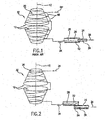
- Fig. 1 is a schematic view of a current tire press 32 that employs a heating conduit 20 arranged coaxial with a central axis 12 of tire mold 10. Heat from saturated steam 34 transferred through heating conduit 20 is used to heat tire mold 10. The circular portions of heating conduit 20 are placed into fluid communication with one another by way of intermittent sections 68. The phase change potential of saturated steam 34 provides both a significant amount of heat along with resulting condensation. Stagnant condensation 52 from steam 34 builds up in heating conduit 20 due to the substantially parallel orientation of heating conduit 20 with respect to the ground. Stagnant condensation 52 in heating conduit 20 reduces the efficiency of heat transfer into tire mold 10. More specifically, the overall heat transfer coefficient of mold 10 is substantially decreased by the presence of condensed steam - i.e. liquid - within heating conduit 20.
- a drainage connector 24 is attached to heating conduit 20 in order to provide an outlet for the removal of stagnant condensation 52 from the system.
- the longitudinal axis 26 of drainage connector 24 is coaxial with the longitudinal axis 28 of heating conduit 20, the removal of stagnant condensation 52 is further hindered since stagnant condensation 52 will be allowed to sit via gravity on the bottom of heating conduit 20 and drainage connector 24.
- the apparatus includes a heating conduit that extends helically with respect to a central axis of a horizontal mold in order to aid in the drainage of condensation formed when using saturated gas in the heating conduit in order to impart heat to the mold.
- the apparatus of the invention also includes a drainage connector configured with the heating conduit with a longitudinal axis aligned below that of the heating conduit in order to more effectively drain condensation from and out of the heating conduit.
- the apparatus includes a horizontal mold that has a central axis and a forming surface disposed radially outward from the central axis.
- the heating conduit is at least partially located radially outward from the forming surface.
- the heating conduit is configured for use with the gas in order to effect heat transfer to the forming surface of the mold.
- the heating conduit extends helically with respect to the central axis in order to effectively drain condensation associated with the use of saturated gas.
- saturated gas the apparatus of the present invention may be used with any type of gas in accordance with other exemplary embodiments.
- the apparatus according to the invention is used to transfer heat into a tire, which is formed at least in part by molding.
- the apparatus includes a horizontal tire mold that has a central axis with tread and sidewall surfaces disposed radially outward from the central axis.
- the heating conduit is at least partially located radially outward from the tread surface of the tire mold.
- the heating conduit is configured for the transport of steam therethrough in order to effect heat transfer to both the tread and sidewall surfaces of the tire mold.
- the heating conduit extends helically with respect to the central axis and is configured so that condensation formed in the heating conduit is at least partially drained via gravity therethrough.
- a drainage connector is placed in fluid communication with the heating conduit.
- the longitudinal axis of the drainage connector is located below a longitudinal axis of a portion of the heating conduit proximate to the drainage connector. In this manner, the drainage connector and the heating conduit are configured to allow condensation in the heating conduit to drain through the drainage connector.
- the heating conduit may be configured in a variety of manners in accordance with various exemplary embodiments.
- the heating conduit may be a channel located in the mold or located adjacent the mold.
- the heating conduit may be partially defined by the mold and partially defined by a helical strip in certain embodiments.
- the heating conduit may be oriented so as to have any degree of slope capable of allowing condensation in the heating conduit to drain therefrom.
- the slope of the heating conduit with respect to a plane normal to the central axis is greater than 0.1°.
- the horizontal mold may be placed into a press configured to apply compressive pressure to the mold in order to assist in the formation of the product.
- the heating conduit may be configured with the press, the mold, or both in accordance with various exemplary embodiments.
- the heating conduit may be configured to work with any type of steam. For instance, saturated steam may be transferred through the heating conduit in order to effect heat transfer to the forming surface of the mold.
- an apparatus for transferring heat into a tire includes a horizontal tire mold with a central axis having tread and sidewall surfaces disposed radially outward therefrom.
- a heating conduit is at least partially located radially outward from the tread surface of the tire mold.
- the heating conduit is configured for the transport of steam therethrough in order to effect heat transfer to the tread and sidewall surfaces of the tire mold.
- the heating conduit extends helically with respect to the central axis and is configured so that condensation formed in the heating conduit is at least partially drained therefrom via gravity.
- the tire mold is divided into upper and lower mold sections so that the heating conduit is also divided into upper and lower heating conduit sections.
- a first drainage connector is placed in fluid communication with the upper heating conduit section.
- a longitudinal axis of the first drainage connector is located below a longitudinal axis of a portion of the upper heating conduit section proximate to the first drainage connector. This configuration allows condensation to drain from the upper heating conduit through the first drainage connector.
- a second drainage connector is placed in fluid communication with the lower heating conduit section. A longitudinal axis of the second drainage connector is located below a longitudinal axis of a portion of the lower heating conduit proximate the second drainage connector. This configuration allows condensation to drain from the lower heating conduit through the second drainage connector.
- FIG. 2 Illustrated in Fig. 2 is an exemplary embodiment of an apparatus for transferring heat into a tire that is formed, at least in part, by molding according to the present invention.
- a horizontal tire press 32 with tire mold 10 is provided in conjunction with a heating conduit 20 that extends helically with respect to a central axis 12 of tire mold 10.
- a gas, such as steam 34 is admitted into heating conduit 20 in order to heat tire mold 10 and the product formed therein.
- Heat is provided as saturated steam 34 condenses into a liquid phase.
- the change from gas to liquid phase provides a significant amount of heat transfer to mold 10 but also forms condensation 64. From the standpoint of heat transfer efficiency, condensation 64 is undesirable because it substantially reduces the overall heat transfer coefficient of the system.
- the helically extending configuration of heating conduit 20 allows condensation 64 to drain from mold 10 due to the effect of gravity. The drainage of condensation 64 from heating conduit 20 will thus eliminate or reduce the negative impact of the presence of condensation 64 on the heat transfer into tire mold 10 and tires formed therein. Additionally, a helically extending heating conduit 20 also provides for a more uniform temperature distribution in tire mold 10, which can result in improved manufacturability, improved product uniformity, lower manufacturing cost for tire products, and improved product quality.
- a drainage connector 24 may also be provided in order to assist with the drainage of condensation 64.
- the longitudinal axis 26 of drainage connector 24 is deliberately misaligned with and located below the longitudinal axis 28 of an end portion of heating conduit 20 so that condensation 64 drains therefrom and may more easily be removed from the system. Drainage connector 24 therefore provides a low point below heating conduit 20 into which condensation 64 will be allowed to exit.
- the combination of heating conduit 20 and drainage connector 24 will allow condensation 64 to be drained through the use of gravity during heating of tire mold 10. The combination will also allow heat to be more efficiently transferred from steam 34 into heating conduit 20 directly through continued condensation on the walls of heating conduit 20 without the substantial build-up of condensation 64 in the system.
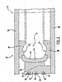
- Fig. 3 is a cross-sectional view of a tire press 32 that may be used in accordance with one exemplary embodiment of the present invention.
- Tire press 32 includes tire mold 10 that has an upper mold section 36 disposed opposite from a lower mold section 38. Both upper and lower mold sections 36, 38 define a pair of sidewall surfaces 16 for use in forming the sidewall portions of a tire.
- Tire mold 10 further includes a central mold section 54 that defines a tread surface 14 for use in forming the tread portion on a green tire placed into tire press 32.
- Tire mold 10 may be made of any suitable material, for instance all or part of tire mold 10 may be constructed of aluminium.
- Tire press 32 provides a compressive or clamping force to tire mold 10 in order to assist in the manufacturing process of tires therein.
- Upper and lower press plates 56, 58 are arranged on either side of tire mold 10 and may be configured so as to be movable relative to one another. Both upper and lower press plates 56,58 may be movable, or alternatively one may be stationary and the other movable so as to effect relative movement between the two plates 56, 58.
- upper press plate 56 is stationary and lower press plate 58, having angled back plate 62 disposed thereon, is movable in a direction along central axis 12.
- Vertical movement of lower press plate 58 will cause angled back plate 62 to move thus forcing radially movable segment 60 radially inward due to an inclined engagement between radially segment 60 and angled back plate 62.
- Radially inward movement of radially movable segment 60 will likewise cause central mold section 54 to move radially inward and exert pressure onto a green tire located in tire mold 10.
- Various components of tire press 32 may be configured so as to be movable in one or more directions, as is commonly known in the art, to provide any desired degree of pressure onto tire mold 10.
- heating conduit 20 is defined by angled back plate 62 and a helical strip 30.
- Heating conduit 20 extends helically downward with respect to central axis 12 so as to allow condensation 64 to drain therefrom through the force of gravity.
- Heat from steam 34 admitted into heating conduit 20 will be transferred through angled back plate 62, into radially movable segment 60, and into central mold section 54 and subsequently into a green tire located in tire mold 10. This heat may further be transferred into other portions of tire mold 10 such as upper and lower mold sections 36, 38 and into other portions of the green tire in tire mold 10.
- upper and lower press plates 56, 58 may be provided with one or more heating elements if so desired in order to further provide heat into tire mold 10.
- Heating conduit 20 may be variously configured in different embodiments. Although shown in Fig. 3 as being defined by angled back plate 62 and helical strip 30 and having a rectangular cross-section, heating conduit 20 may be a double called pipe or may have various cross-sectional shapes such as square, rectangular, circular, trapezoidal, etc. Further, the cross-section of heating conduit 20 need not be uniform throughout its entire helically extended length. For example, heating conduit 20 may be made smaller in cross-sectional size so that heating conduit 20 is smaller at those portions of heating conduit 20 proximate to upper press plate 56 while heating conduit 20 is larger at those portions of heating conduit 20 proximate to lower press plate 58. Variations in the size, shape, or material making up heating conduit 20 allows for the achievement of a desired heat transfer into tire mold 10.
- Fig. 4 shows a further embodiment in which heating conduit 20 is constructed so as to have a square cross-sectional shape.
- Three sides of heating conduit 20 are defined by an end section of tire mold 10.
- the forth side of heating conduit 20 is made by a helical strip 30 that extends around tire mold 10 and is oriented so as to extend helically with respect to central axis 12.
- the entire length of heating conduit 20 may be configured as shown in Fig. 5 , or alternatively the arrangement shown in Fig. 5 may make up two or three passes of heating conduit 20 around tire mold 10.
- the rest of heating conduit 20 may be provided as a pipe or similar component.
- Helical strip 30 may be attached to tire mold 10 in any manner commonly known to one of ordinary skill in the art, for instance welding, adhesives, or mechanical fasteners may be used.
- FIG. 5 and 6 A further embodiment of tire mold 10 is shown in Figs. 5 and 6 .
- tire mold 10 rests on lower press plate 58 and employs a heating conduit 20 that is formed by a helical strip 30 and lower mold section 38 and extends helically in the direction of central axis 12.
- Heating conduit 20 is inclined at an angle ⁇ with respect to a plane 22 that is normal to central axis 12, angle ⁇ may be of any degree so as to allow condensation 64 to drain from heating conduit 20 via the force of gravity. Additionally, angle ⁇ may be selected so as to ensure an appropriate length of heating conduit 20 is provided while condensation flow in heating conduit 20 is still adequate in order to ensure the correct heat transfer into tire mold 10.
- angle ⁇ may be 0.5°, 0.75°, 1°, 2°, 5°, 7°, 10°, 15°, 20°, or 25°. In certain embodiments, angle ⁇ may be any angle greater than 0.1°. Further, angle ⁇ may vary in degree throughout the length of heating conduit 20. It is to be understood that any suitable angle ⁇ may be employed in accordance with various exemplary embodiments of the present invention.
- Tire mold 10 may also be configured so that more than one drainage connector 24 is present.
- Fig. 7 shows a schematic view similar to Fig. 2 in which tire press 32 includes tire mold 10 divided into both an upper mold section 36 and a lower mold section 38. Since upper and lower mold section 36, 38 split tire mold 10 at its mid-point, heating conduit 20 is also divided into an upper heating conduit section 40 incorporated into upper mold 36 and into a lower heating conduit section 42 incorporated into lower mold section 38.
- a first drainage connector 44 is attached to the outlet end of upper heating conduit section 40.
- First drainage connector 44 has a longitudinal axis 46 that is misaligned with and located below the longitudinal axis 28 of the end portion of upper heating conduit section 40.
- first drainage connector 44 may be arranged so that longitudinal axis 46 and longitudinal axis 28 are closer to, yet not touching one another. This type of arrangement will still provide for a low point into which condensation 64 may drain from upper heating conduit section 40.
- a second drainage connector 48 may be arranged with lower heating conduit section 42 in the same manner as previously discussed with respect to first drainage connector 44 and upper heating conduit section 40. Once again, the longitudinal axis 50 of second drainage connector 48 is positioned below the longitudinal axis 28 of the end portion of lower heating conduit section 42. Although shown as a pair of drainage connectors 44, 48 it is to be understood that any number of drainage connectors may be used in accordance with various exemplary embodiments of the present invention.
- Drainage connectors 44, 48 may be attached to the heating conduit sections 40, 42 by any method commonly known in the art. For instance, these components may be integrally formed with one another, may be attached through welding, adhesives, mechanical fasteners, pins, bolts, or any other suitable method. Drainage connectors 44, 48 may be permanently attached to heating conduit sections 40, 42 of may be configured so as to be removably attached thereto. Steam 34 may be introduced into heating conduit 20 through an inlet (not shown). Although described as being used with a horizontal tire mold 10, the present invention may be employed in tire molds that are vertical or oriented at various angles.
- a conventional tire mold 10 was employed, such as one used in the tire press 32 of Fig. 1 , that included a series of parallel heating conduits 20.
- a predetermined location within the tire was heated from ambient to 120° C in approximately 110 minutes by the use of 150 °C steam 34.
- the conventional tire mold 10 was then turned on its side so as to be rotated 90°. Therefore, instead of being parallel to the ground or horizontal, heating conduit 20 extended up and down with respect to the ground.
- the mold was positioned so that the same predetermined location where temperature was measured for horizontal operation was now located at the top of the mold 10.
- condensation 64 would not accumulate in the heating conduit 20 at positions near the predetermined location but instead would be drained by gravity to the portions of heating conduit 20 closer to the ground.
- a time of less than 80 minutes was needed in order to heat the same predetermined location from a temperature of ambient to 120° C. This represented a substantial improvement in heating time as compared to when conventional tire mold 10 was oriented in the previous, horizontal position depicted in Fig. 1 .
Landscapes
- Engineering & Computer Science (AREA)
- Mechanical Engineering (AREA)
- Physics & Mathematics (AREA)
- Health & Medical Sciences (AREA)
- Oral & Maxillofacial Surgery (AREA)
- Thermal Sciences (AREA)
- Moulds For Moulding Plastics Or The Like (AREA)
- Heating, Cooling, Or Curing Plastics Or The Like In General (AREA)
Applications Claiming Priority (1)
| Application Number | Priority Date | Filing Date | Title |
|---|---|---|---|
| US10/880,733 US7160090B2 (en) | 2003-10-31 | 2004-06-30 | Tire mold with helically extending heating conduit |
Publications (3)
| Publication Number | Publication Date |
|---|---|
| EP1612022A1 EP1612022A1 (en) | 2006-01-04 |
| EP1612022A8 EP1612022A8 (en) | 2006-03-29 |
| EP1612022B1 true EP1612022B1 (en) | 2008-10-01 |
Family
ID=34937693
Family Applications (1)
| Application Number | Title | Priority Date | Filing Date |
|---|---|---|---|
| EP05013913A Expired - Lifetime EP1612022B1 (en) | 2004-06-30 | 2005-06-28 | Tire mold with helically extending heating conduit |
Country Status (9)
| Country | Link |
|---|---|
| US (1) | US7160090B2 (enExample) |
| EP (1) | EP1612022B1 (enExample) |
| JP (1) | JP2006015751A (enExample) |
| KR (1) | KR20060048665A (enExample) |
| CN (1) | CN1721159A (enExample) |
| BR (1) | BRPI0502193A (enExample) |
| CA (1) | CA2505039A1 (enExample) |
| DE (1) | DE602005010000D1 (enExample) |
| MX (1) | MXPA05006948A (enExample) |
Families Citing this family (9)
| Publication number | Priority date | Publication date | Assignee | Title |
|---|---|---|---|---|
| ITMI20060557A1 (it) * | 2006-03-24 | 2007-09-25 | Persico Spa | Stampo con condotti di termoregolazione e suo metodo di realizzazione |
| US9138950B2 (en) * | 2011-08-30 | 2015-09-22 | Bridgestone Americas Tire Operations, Llc | Tire molding apparatus |
| FR2980135B1 (fr) * | 2011-09-21 | 2014-06-13 | Michelin Soc Tech | Presse de cuisson de pneumatique comprenant une chambre de chauffage a vapeur |
| CN102615811A (zh) * | 2012-03-31 | 2012-08-01 | 上海凌力特殊钢发展有限公司 | 旋转式热灌装吹瓶模模腔分解装置 |
| KR20160022511A (ko) | 2014-08-20 | 2016-03-02 | 금호타이어 주식회사 | 타이어 가황기의 응축수 배출장치 |
| JP6579808B2 (ja) * | 2015-06-09 | 2019-09-25 | 株式会社ブリヂストン | タイヤモールド、及びタイヤモールドの製造方法 |
| CN114734665B (zh) * | 2022-03-14 | 2024-08-02 | 青岛森麒麟轮胎股份有限公司 | 双汽室轮胎模具 |
| DE102022127194A1 (de) * | 2022-10-18 | 2024-04-18 | HERBERT Tire Tooling GmbH & Co. KG | Schließring für eine Reifenform, Reifenform sowie Verfahren zur Vulkanisierung |
| IT202200026979A1 (it) * | 2022-12-28 | 2024-06-28 | Pirelli | “Apparato per la vulcanizzazione e lo stampaggio di pneumatici e metodo per preriscaldare settori circonferenziali in un apparato per la vulcanizzazione e lo stampaggio di pneumatici” |
Family Cites Families (25)
| Publication number | Priority date | Publication date | Assignee | Title |
|---|---|---|---|---|
| US1582714A (en) * | 1924-01-11 | 1926-04-27 | Scranton Button Company | Die for molding plastic material |
| US1630113A (en) * | 1926-09-08 | 1927-05-24 | Mattia Brothers Inc De | Tire-vulcanizing mold |
| US1895135A (en) * | 1929-07-08 | 1933-01-24 | Rohn Wilhelm | Water-cooled mold |
| NL40209C (enExample) * | 1932-12-20 | |||
| US2874751A (en) * | 1956-03-13 | 1959-02-24 | Thermel Inc | Temperature controlled press |
| US2932853A (en) * | 1957-05-23 | 1960-04-19 | Louis T Fike | Tire capping apparatus |
| US3181200A (en) * | 1962-12-19 | 1965-05-04 | Metro Goldwyn Mayer Inc | Heating and cooling means for flat phonograph record die |
| US3633656A (en) * | 1970-02-20 | 1972-01-11 | United States Steel Corp | Apparatus for making ingots |
| US3868203A (en) * | 1971-05-17 | 1975-02-25 | Nrm Corp | Tire molding machine |
| GB1509362A (en) * | 1977-01-17 | 1978-05-04 | Emi Electrola Gmbh | Disc record press |
| US4116595A (en) * | 1977-09-23 | 1978-09-26 | Ohio Machine Company, Inc. | Tire mold apparatus |
| US4184823A (en) * | 1978-10-26 | 1980-01-22 | The Goodyear Tire & Rubber Company | Tire mold press |
| IT1160163B (it) * | 1983-01-12 | 1987-03-04 | Pirelli | Miglioramenti ai dispositivi di vulcanizzazione per pneumatici |
| IT1198210B (it) * | 1986-12-01 | 1988-12-21 | Pirelli | Stampo per pneumatici e dispositivo automatico per lo smontaggio rapido dalla relativa pressa |
| EP0513348B1 (en) | 1990-01-29 | 1995-04-05 | Sumitomo Gomu Kogyo Kabushiki Kaisha | Vulcanization method and apparatus for elastomer articles |
| JPH0976238A (ja) | 1995-09-14 | 1997-03-25 | Kobe Steel Ltd | タイヤ加硫プレス |
| JP2951576B2 (ja) * | 1995-09-14 | 1999-09-20 | 株式会社神戸製鋼所 | タイヤ加硫装置 |
| US5971742A (en) * | 1996-09-18 | 1999-10-26 | Pyramid Composites Manufacturing Limited Partnership | Apparatus for molding composite articles |
| JPH10291236A (ja) * | 1997-04-18 | 1998-11-04 | Sony Corp | 金型装置及びこれを用いた成形方法 |
| JP2001079851A (ja) | 1999-09-17 | 2001-03-27 | Kobe Steel Ltd | 加硫機 |
| JP4266272B2 (ja) * | 2000-06-07 | 2009-05-20 | 本田技研工業株式会社 | 樹脂成形金型 |
| US6413068B1 (en) * | 2000-07-10 | 2002-07-02 | The Goodyear Tire & Rubber Company | Tire mold heat transfer system |
| JP2002160247A (ja) * | 2000-11-27 | 2002-06-04 | Unitta Co Ltd | ベルトの製造方法 |
| US6884369B2 (en) * | 2001-12-17 | 2005-04-26 | Essilor International (Compagnie Generale D'optique | Mold and a method of hot-forming a thermoplastic lens |
| US6916164B2 (en) * | 2002-12-23 | 2005-07-12 | The Goodyear Tire & Rubber Company | Tire mold having improved heat transfer characteristics |
-
2004
- 2004-06-30 US US10/880,733 patent/US7160090B2/en not_active Expired - Fee Related
-
2005
- 2005-04-22 CA CA002505039A patent/CA2505039A1/en not_active Abandoned
- 2005-05-30 CN CNA2005100730823A patent/CN1721159A/zh active Pending
- 2005-06-10 BR BR0502193-6A patent/BRPI0502193A/pt not_active IP Right Cessation
- 2005-06-24 MX MXPA05006948A patent/MXPA05006948A/es active IP Right Grant
- 2005-06-28 EP EP05013913A patent/EP1612022B1/en not_active Expired - Lifetime
- 2005-06-28 DE DE602005010000T patent/DE602005010000D1/de not_active Expired - Lifetime
- 2005-06-29 KR KR1020050056753A patent/KR20060048665A/ko not_active Withdrawn
- 2005-06-30 JP JP2005193163A patent/JP2006015751A/ja active Pending
Also Published As
| Publication number | Publication date |
|---|---|
| US20050095308A1 (en) | 2005-05-05 |
| EP1612022A1 (en) | 2006-01-04 |
| EP1612022A8 (en) | 2006-03-29 |
| KR20060048665A (ko) | 2006-05-18 |
| JP2006015751A (ja) | 2006-01-19 |
| BRPI0502193A (pt) | 2006-02-07 |
| DE602005010000D1 (de) | 2008-11-13 |
| CN1721159A (zh) | 2006-01-18 |
| CA2505039A1 (en) | 2005-12-30 |
| US7160090B2 (en) | 2007-01-09 |
| MXPA05006948A (es) | 2006-01-24 |
Similar Documents
| Publication | Publication Date | Title |
|---|---|---|
| EP1612022B1 (en) | Tire mold with helically extending heating conduit | |
| EP2468469B1 (en) | Base-tire manufacturing method, vulcanization device | |
| EP0978370A2 (en) | Vulcanising method and vulcanising apparatus for a tyre | |
| RU2235641C2 (ru) | Способ и устройство формования и вулканизации шин для колес транспортных средств | |
| JP2009149078A (ja) | タイヤ型 | |
| EP2072233B1 (en) | Tire mold | |
| CN102666051A (zh) | 轮胎硫化设备 | |
| JP6651779B2 (ja) | タイヤ加硫装置 | |
| JP2008168490A (ja) | 空気入りタイヤの製造方法及びその製造装置 | |
| CN113524645B (zh) | 成型装置 | |
| JP5106782B2 (ja) | タイヤ加硫装置 | |
| US2895166A (en) | Molds for retreading or recapping vehicle tires | |
| WO2013001964A1 (ja) | 剛性中子、及びそれを用いたタイヤの製造方法 | |
| JP6926790B2 (ja) | タイヤ加硫方法及びタイヤ加硫装置 | |
| JP4678150B2 (ja) | ゴムロールの製造装置、製造システムおよびゴムロールの製造方法 | |
| CN106578272A (zh) | 一种巧克力浇注装置 | |
| US1917262A (en) | Apparatus for retreading tire casings | |
| CN120418073A (zh) | 用于硫化和模制轮胎的设备以及用于预热用于硫化和模制轮胎的设备中的周向扇区的方法 | |
| KR101207638B1 (ko) | 팽창성 블래더 | |
| KR100867600B1 (ko) | 무브래다 가류기의 코어 몰드 예열 장치 | |
| EP3266599A1 (en) | Tire vulcanizing apparatus and tire vulcanizing method | |
| JP2004209928A (ja) | タイヤ加硫装置におけるブラダーの流体給排ヘッド | |
| KR20230053092A (ko) | 타이어 제조용 가류금형 | |
| CN104290224A (zh) | 橡胶的硫化装置以及硫化方法 | |
| KR101584791B1 (ko) | 방현재의 제조장치 |
Legal Events
| Date | Code | Title | Description |
|---|---|---|---|
| PUAI | Public reference made under article 153(3) epc to a published international application that has entered the european phase |
Free format text: ORIGINAL CODE: 0009012 |
|
| AK | Designated contracting states |
Kind code of ref document: A1 Designated state(s): AT BE BG CH CY CZ DE DK EE ES FI FR GB GR HU IE IS IT LI LT LU MC NL PL PT RO SE SI SK TR |
|
| AX | Request for extension of the european patent |
Extension state: AL BA HR LV MK YU |
|
| 17P | Request for examination filed |
Effective date: 20060127 |
|
| RIN1 | Information on inventor provided before grant (corrected) |
Inventor name: YANG, SHAW XIAOFENG Inventor name: KERECHANIN, CHRIS |
|
| AKX | Designation fees paid |
Designated state(s): DE ES FR GB IT |
|
| 17Q | First examination report despatched |
Effective date: 20060330 |
|
| GRAP | Despatch of communication of intention to grant a patent |
Free format text: ORIGINAL CODE: EPIDOSNIGR1 |
|
| GRAS | Grant fee paid |
Free format text: ORIGINAL CODE: EPIDOSNIGR3 |
|
| GRAA | (expected) grant |
Free format text: ORIGINAL CODE: 0009210 |
|
| AK | Designated contracting states |
Kind code of ref document: B1 Designated state(s): DE ES FR GB IT |
|
| REG | Reference to a national code |
Ref country code: GB Ref legal event code: FG4D |
|
| REF | Corresponds to: |
Ref document number: 602005010000 Country of ref document: DE Date of ref document: 20081113 Kind code of ref document: P |
|
| PG25 | Lapsed in a contracting state [announced via postgrant information from national office to epo] |
Ref country code: ES Free format text: LAPSE BECAUSE OF FAILURE TO SUBMIT A TRANSLATION OF THE DESCRIPTION OR TO PAY THE FEE WITHIN THE PRESCRIBED TIME-LIMIT Effective date: 20090112 |
|
| PLBE | No opposition filed within time limit |
Free format text: ORIGINAL CODE: 0009261 |
|
| STAA | Information on the status of an ep patent application or granted ep patent |
Free format text: STATUS: NO OPPOSITION FILED WITHIN TIME LIMIT |
|
| 26N | No opposition filed |
Effective date: 20090702 |
|
| GBPC | Gb: european patent ceased through non-payment of renewal fee |
Effective date: 20090628 |
|
| PG25 | Lapsed in a contracting state [announced via postgrant information from national office to epo] |
Ref country code: GB Free format text: LAPSE BECAUSE OF NON-PAYMENT OF DUE FEES Effective date: 20090628 |
|
| PGFP | Annual fee paid to national office [announced via postgrant information from national office to epo] |
Ref country code: FR Payment date: 20100709 Year of fee payment: 6 |
|
| PGFP | Annual fee paid to national office [announced via postgrant information from national office to epo] |
Ref country code: IT Payment date: 20100621 Year of fee payment: 6 |
|
| PGFP | Annual fee paid to national office [announced via postgrant information from national office to epo] |
Ref country code: DE Payment date: 20100625 Year of fee payment: 6 |
|
| PG25 | Lapsed in a contracting state [announced via postgrant information from national office to epo] |
Ref country code: IT Free format text: LAPSE BECAUSE OF NON-PAYMENT OF DUE FEES Effective date: 20110628 |
|
| REG | Reference to a national code |
Ref country code: FR Ref legal event code: ST Effective date: 20120229 |
|
| REG | Reference to a national code |
Ref country code: DE Ref legal event code: R119 Ref document number: 602005010000 Country of ref document: DE Effective date: 20120103 |
|
| PG25 | Lapsed in a contracting state [announced via postgrant information from national office to epo] |
Ref country code: FR Free format text: LAPSE BECAUSE OF NON-PAYMENT OF DUE FEES Effective date: 20110630 Ref country code: DE Free format text: LAPSE BECAUSE OF NON-PAYMENT OF DUE FEES Effective date: 20120103 |