EP1607678A2 - Lampe avec des diodes électroluminescentes pour produire un faisceau large ou un faisceau ponctuel - Google Patents
Lampe avec des diodes électroluminescentes pour produire un faisceau large ou un faisceau ponctuel Download PDFInfo
- Publication number
- EP1607678A2 EP1607678A2 EP05076414A EP05076414A EP1607678A2 EP 1607678 A2 EP1607678 A2 EP 1607678A2 EP 05076414 A EP05076414 A EP 05076414A EP 05076414 A EP05076414 A EP 05076414A EP 1607678 A2 EP1607678 A2 EP 1607678A2
- Authority
- EP
- European Patent Office
- Prior art keywords
- led
- luminaire according
- housing
- lamp
- optical device
- Prior art date
- Legal status (The legal status is an assumption and is not a legal conclusion. Google has not performed a legal analysis and makes no representation as to the accuracy of the status listed.)
- Withdrawn
Links
Images


Classifications
-
- F—MECHANICAL ENGINEERING; LIGHTING; HEATING; WEAPONS; BLASTING
- F21—LIGHTING
- F21V—FUNCTIONAL FEATURES OR DETAILS OF LIGHTING DEVICES OR SYSTEMS THEREOF; STRUCTURAL COMBINATIONS OF LIGHTING DEVICES WITH OTHER ARTICLES, NOT OTHERWISE PROVIDED FOR
- F21V23/00—Arrangement of electric circuit elements in or on lighting devices
- F21V23/04—Arrangement of electric circuit elements in or on lighting devices the elements being switches
-
- F—MECHANICAL ENGINEERING; LIGHTING; HEATING; WEAPONS; BLASTING
- F21—LIGHTING
- F21L—LIGHTING DEVICES OR SYSTEMS THEREOF, BEING PORTABLE OR SPECIALLY ADAPTED FOR TRANSPORTATION
- F21L4/00—Electric lighting devices with self-contained electric batteries or cells
- F21L4/02—Electric lighting devices with self-contained electric batteries or cells characterised by the provision of two or more light sources
- F21L4/022—Pocket lamps
- F21L4/027—Pocket lamps the light sources being a LED
-
- F—MECHANICAL ENGINEERING; LIGHTING; HEATING; WEAPONS; BLASTING
- F21—LIGHTING
- F21S—NON-PORTABLE LIGHTING DEVICES; SYSTEMS THEREOF; VEHICLE LIGHTING DEVICES SPECIALLY ADAPTED FOR VEHICLE EXTERIORS
- F21S9/00—Lighting devices with a built-in power supply; Systems employing lighting devices with a built-in power supply
- F21S9/02—Lighting devices with a built-in power supply; Systems employing lighting devices with a built-in power supply the power supply being a battery or accumulator
- F21S9/03—Lighting devices with a built-in power supply; Systems employing lighting devices with a built-in power supply the power supply being a battery or accumulator rechargeable by exposure to light
-
- F—MECHANICAL ENGINEERING; LIGHTING; HEATING; WEAPONS; BLASTING
- F21—LIGHTING
- F21V—FUNCTIONAL FEATURES OR DETAILS OF LIGHTING DEVICES OR SYSTEMS THEREOF; STRUCTURAL COMBINATIONS OF LIGHTING DEVICES WITH OTHER ARTICLES, NOT OTHERWISE PROVIDED FOR
- F21V14/00—Controlling the distribution of the light emitted by adjustment of elements
- F21V14/04—Controlling the distribution of the light emitted by adjustment of elements by movement of reflectors
- F21V14/045—Controlling the distribution of the light emitted by adjustment of elements by movement of reflectors in portable lighting devices
-
- F—MECHANICAL ENGINEERING; LIGHTING; HEATING; WEAPONS; BLASTING
- F21—LIGHTING
- F21V—FUNCTIONAL FEATURES OR DETAILS OF LIGHTING DEVICES OR SYSTEMS THEREOF; STRUCTURAL COMBINATIONS OF LIGHTING DEVICES WITH OTHER ARTICLES, NOT OTHERWISE PROVIDED FOR
- F21V14/00—Controlling the distribution of the light emitted by adjustment of elements
- F21V14/06—Controlling the distribution of the light emitted by adjustment of elements by movement of refractors
- F21V14/065—Controlling the distribution of the light emitted by adjustment of elements by movement of refractors in portable lighting devices
-
- F—MECHANICAL ENGINEERING; LIGHTING; HEATING; WEAPONS; BLASTING
- F21—LIGHTING
- F21V—FUNCTIONAL FEATURES OR DETAILS OF LIGHTING DEVICES OR SYSTEMS THEREOF; STRUCTURAL COMBINATIONS OF LIGHTING DEVICES WITH OTHER ARTICLES, NOT OTHERWISE PROVIDED FOR
- F21V23/00—Arrangement of electric circuit elements in or on lighting devices
- F21V23/04—Arrangement of electric circuit elements in or on lighting devices the elements being switches
- F21V23/0435—Arrangement of electric circuit elements in or on lighting devices the elements being switches activated by remote control means
-
- F—MECHANICAL ENGINEERING; LIGHTING; HEATING; WEAPONS; BLASTING
- F21—LIGHTING
- F21L—LIGHTING DEVICES OR SYSTEMS THEREOF, BEING PORTABLE OR SPECIALLY ADAPTED FOR TRANSPORTATION
- F21L4/00—Electric lighting devices with self-contained electric batteries or cells
- F21L4/08—Electric lighting devices with self-contained electric batteries or cells characterised by means for in situ recharging of the batteries or cells
-
- F—MECHANICAL ENGINEERING; LIGHTING; HEATING; WEAPONS; BLASTING
- F21—LIGHTING
- F21S—NON-PORTABLE LIGHTING DEVICES; SYSTEMS THEREOF; VEHICLE LIGHTING DEVICES SPECIALLY ADAPTED FOR VEHICLE EXTERIORS
- F21S8/00—Lighting devices intended for fixed installation
- F21S8/08—Lighting devices intended for fixed installation with a standard
-
- F—MECHANICAL ENGINEERING; LIGHTING; HEATING; WEAPONS; BLASTING
- F21—LIGHTING
- F21V—FUNCTIONAL FEATURES OR DETAILS OF LIGHTING DEVICES OR SYSTEMS THEREOF; STRUCTURAL COMBINATIONS OF LIGHTING DEVICES WITH OTHER ARTICLES, NOT OTHERWISE PROVIDED FOR
- F21V29/00—Protecting lighting devices from thermal damage; Cooling or heating arrangements specially adapted for lighting devices or systems
- F21V29/50—Cooling arrangements
- F21V29/502—Cooling arrangements characterised by the adaptation for cooling of specific components
- F21V29/507—Cooling arrangements characterised by the adaptation for cooling of specific components of means for protecting lighting devices from damage, e.g. housings
-
- F—MECHANICAL ENGINEERING; LIGHTING; HEATING; WEAPONS; BLASTING
- F21—LIGHTING
- F21V—FUNCTIONAL FEATURES OR DETAILS OF LIGHTING DEVICES OR SYSTEMS THEREOF; STRUCTURAL COMBINATIONS OF LIGHTING DEVICES WITH OTHER ARTICLES, NOT OTHERWISE PROVIDED FOR
- F21V31/00—Gas-tight or water-tight arrangements
-
- F—MECHANICAL ENGINEERING; LIGHTING; HEATING; WEAPONS; BLASTING
- F21—LIGHTING
- F21W—INDEXING SCHEME ASSOCIATED WITH SUBCLASSES F21K, F21L, F21S and F21V, RELATING TO USES OR APPLICATIONS OF LIGHTING DEVICES OR SYSTEMS
- F21W2131/00—Use or application of lighting devices or systems not provided for in codes F21W2102/00-F21W2121/00
- F21W2131/10—Outdoor lighting
- F21W2131/103—Outdoor lighting of streets or roads
-
- F—MECHANICAL ENGINEERING; LIGHTING; HEATING; WEAPONS; BLASTING
- F21—LIGHTING
- F21Y—INDEXING SCHEME ASSOCIATED WITH SUBCLASSES F21K, F21L, F21S and F21V, RELATING TO THE FORM OR THE KIND OF THE LIGHT SOURCES OR OF THE COLOUR OF THE LIGHT EMITTED
- F21Y2107/00—Light sources with three-dimensionally disposed light-generating elements
- F21Y2107/30—Light sources with three-dimensionally disposed light-generating elements on the outer surface of cylindrical surfaces, e.g. rod-shaped supports having a circular or a polygonal cross section
-
- F—MECHANICAL ENGINEERING; LIGHTING; HEATING; WEAPONS; BLASTING
- F21—LIGHTING
- F21Y—INDEXING SCHEME ASSOCIATED WITH SUBCLASSES F21K, F21L, F21S and F21V, RELATING TO THE FORM OR THE KIND OF THE LIGHT SOURCES OR OF THE COLOUR OF THE LIGHT EMITTED
- F21Y2115/00—Light-generating elements of semiconductor light sources
- F21Y2115/10—Light-emitting diodes [LED]
-
- Y—GENERAL TAGGING OF NEW TECHNOLOGICAL DEVELOPMENTS; GENERAL TAGGING OF CROSS-SECTIONAL TECHNOLOGIES SPANNING OVER SEVERAL SECTIONS OF THE IPC; TECHNICAL SUBJECTS COVERED BY FORMER USPC CROSS-REFERENCE ART COLLECTIONS [XRACs] AND DIGESTS
- Y02—TECHNOLOGIES OR APPLICATIONS FOR MITIGATION OR ADAPTATION AGAINST CLIMATE CHANGE
- Y02B—CLIMATE CHANGE MITIGATION TECHNOLOGIES RELATED TO BUILDINGS, e.g. HOUSING, HOUSE APPLIANCES OR RELATED END-USER APPLICATIONS
- Y02B20/00—Energy efficient lighting technologies, e.g. halogen lamps or gas discharge lamps
- Y02B20/72—Energy efficient lighting technologies, e.g. halogen lamps or gas discharge lamps in street lighting
Definitions
- the present invention relates to a luminaire with a housing, at least one in arranged on the housing LED bulbs and with an optical device which in a distance to the LED light source in a beam path of at least one light beam is arranged and can reflect a light beam and / or break.
- LED light-emitting diode
- the well-known prior art with a LED bulbs shows the disadvantage that such lights are not focusable and therefore only be used to generate a broad jet.
- When trying with a LED bulbs also produce a spot beam, so far it is only possible To produce wide beams with reduced width.
- Such lights can not Generation of a spot beam can be used and are not yet comparable with conventional lights, with which a spot beam can be adjusted.
- the object of the present invention is therefore a luminaire with at least one LED to create as a light source, produced with both wide-beam and a spot beam can be.
- the object is achieved in that the LED bulbs in one is arranged upstream or in the optical device existing focal point.
- the arrangement of the LED light source in the upstream or in the optical Device lying focal point is a prerequisite for using the optical Device, either a reflector, a lens device or a combination same, a spot beam can be generated.
- the optical device has a mirror reflector, the Beam path limited.
- Another advantage of the luminaire according to the invention results when the optical Device having an aspherical lens.
- the distance between the LED bulb and the optical Device can be broad-beam and generate at least one spot beam.
- the lamp can be used as a street lamp. Because of a low energy consumption with optimized emission can be such Street light can be operated with an accumulator powered by solar energy becomes.
- FIG. 6 shows a handheld projector 10 in FIG partially cutaway illustration.
- the hand lamp 10 has a housing 11, which is essentially made in one piece.
- the housing 11 may be made of conventional Materials consist, for example, of aluminum, polyethylene or another suitable material.
- the housing 11 is in the region of an upper side to a handle 12 shaped.
- the housing 11 On both sides of the handle 12 are formed means for fastening a carrying strap, which represent two eyelets 13 in the present embodiment.
- the housing In the area of one Bottom, the housing is formed to bearing surfaces, for example, the illustrated Stand feet 14, with which the hand lamp 10 can be placed on a pad.
- the housing 11 further has an opening which is circular Recess 15 is formed. In other embodiments, the opening may also have other geometric shapes.
- an LED bulb 16 Inside the housing 11 is an LED bulb 16 arranged. The LED illuminant 16 is in the region of the recess 15 of the housing 11 is located and lies at the focal point of an optical device 30 (details run below).
- the optical device 30 comprises in a first embodiment a mirror reflector 30.1 and a windshield 30.2, in a second embodiment only an aspherical lens 30.3 and in a third embodiment a combination of Mirror reflector 30.1 and aspherical lens 30.3.
- a Aspherical lens 30.3 can optionally also be provided with a windshield 30.2.
- a sealing ring 19 is positioned, which prevents the penetration of dust and / or moisture into the housing 11.
- the LED lamp 16 is seated on a holder 19 in the housing 11.
- the holder 19 may consist of an elastic material, such as a plastic or from Rubber 15.
- shocks for example, from the outside on the Housing 11 act, for example, in a rough lowering of the hand lamp 10, damped, so that damage to the LED bulb 16 is avoided.
- a power source 17 for supplying the LED lighting means 16 arranged with energy is in the present case from a plurality of accumulators 18, which are connected via lines 20 to the LED illuminator 16 are connected. Alternatively, batteries can be used for power supply.
- the housing is an on / off switch 23rd assigned, via lines 20 to the accumulators 18 and the LED illuminator 17th connected is.
- acoustic and / or optical Signaling be arranged, for example, a (light) diode or a speaker. These means are used to signal the imminent end of the operating period, ie the time at which the stored energy in the accumulators 18 is consumed or the capacity of the accumulators 18 is exhausted.
- a circuit is arranged in the housing 11, consisting of electronic components 22 on a board 21. Once the capacity of the accumulators falls below a certain threshold, this is determined by the acoustic and / or optical means signaled.
- the circuit on the one hand with the accumulators and on the other hand connected to the acoustic and / or optical means by the Circuit operated automatically.
- the capacity of the accumulators 18 It is also possible to measure the voltage to determine the remaining operating time.
- the operation of the optical and / or acoustic means may, for example, be five minutes take place before the end of the operating period. The time at which before the end of the Battery capacity can be warned by programming the circuit accordingly be adjusted.
- LED lighting means 16 it is also possible to arrange a plurality of LED lighting means 16 in the housing 11. So can For example, two LED bulbs with different energy consumption and be used according to different luminosity, for example 1 watt or more. Depending on the capacity of the accumulators 18, the operation of the two LED bulb 16 automatically controlled by the circuit. In this case, that indicates Housing 11 a single on / off switch 23, with the hand lamp 10 in Operation can be taken. As long as sufficient capacity is available, Both LED bulbs 16 or alternatively the LED bulbs 16 with the larger Energy intake operated. Once the capacity is below a certain threshold falls, the LED bulb 16 is turned off with greater energy consumption and only operated the LED bulb 16 with less energy consumption.
- the LED lighting means 16, a control element for controlling the intensity be associated with the generated light beam, for example, a controller with which the intensity preferably continuously variable.
- the housing 11 also has a socket 24. With the help of the socket 24, the power source 17 and / or the at least one LED lighting means 16 connectable to an external power source. On In this way, the at least one LED illuminant 16 can be independent of the inside of the housing 11 arranged power source 17 are operated. Furthermore, the external Power source can be used to charge the batteries 18.
- the Housing 11 a transport lock 25. With the help of the transport lock 25 of the Operation of the lamps 16 are inhibited regardless of the switch 23. To this In this way, an accidental operation of the handheld spotlight 10 during the Transports are avoided.
- the operation of the portable headlight 10 by means of a wireless Remote control can have an on / off switch, the in its function corresponds to the switch 11 mounted on the housing 11. In this way each lamp 16 can be actuated.
- the remote control can be a controller for the intensity of the generated light beam.
- the Remote but a switch on, with the two aforementioned functions combined are controllable.
- a pushbutton the simple operation of each Lamp 16 turns on or off. A long press on the button is used for control the intensity of the generated light beam, so for dimming.
- the Remote control the same optical and / or acoustic means of signaling the End of the operating time have as the hand lamp 10th
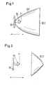
- the LED lamp 16 is disposed at the focal point F1, the upstream ago Exit of a light beam from the lamp is.
- the reflector 30.1 limits the Beam path of the light emitted from the LED bulb 16 light rays.
- On the Opening side of the mirror reflector 30.1 is a translucent disc 30.2 arranged.
- the beam angle of the LED light source is 120 to 160 °.
- the distance of the LED bulb 16 of the mirror reflector 30.1 is changeable (see Pfeilrichtng), depending after, whether a wide beam or a spot beam is to be generated.
- a second embodiment of the optical device 30 is shown.
- the LED bulb 16 is in the downstream focal point 1 of an aspheric lens 30.3 arranged.
- the aspherical lens 30.3 is with a straight base 30.4 the LED bulb 16 facing.
- the distance between the LED bulb 16 and the aspherical lens 30.3 changeable, depending on whether a Wide beam or a spot beam to be generated.
- the change in the distance between the LED bulb 16 and the optical Device 30 is effected by known adjusting means, which are not described here should be. In general, the optical device 30 will be adjusted and not the LED bulb 16.
- the LED illuminant 16 is in relation to the optical device 30 Third embodiment of the present invention shown schematically.
- the LED bulb 16 is also in a mirror reflector 30.1 and Although at the focal point F1, but there is rotatably mounted. The rotation takes place around with a Primary light beam coincident optical axis.
- Such an embodiment is Can be used in a beacon, for example a blue light.
- a power transmission takes place in this embodiment via a slip ring (not shown), with carbon brushes. With a 1 watt LED, it is possible to the legally prescribed amount of light produce.
- a holder for a plurality of LED bulbs is shown schematically, in a lamp according to the present invention can be used.
- a triangular or polygonal carrier 31, with an appropriate number of faces, in the middle an all-round beacon is installed, has at least one side surface 32 at least LED bulb 16 on.
- At least one aspheric lens 30.3 moves concentrically around the carrier 31, at a distance through which the LED lighting means 16 lie in the central focus F1 of the aspheric lens.
- the carrier has four side surfaces 32, so that four LED bulbs with a beam angle of 110 ° the meet legal requirements for an all-round light of 360 °.
- a light reflector 30.1 be used instead of the aspherical lens 30.3, in this embodiment.
- the light reflector 30.1 then rotates at such a distance around the LED bulbs 16 that they are in the focal point F1.
- Fig. 5 is schematically the upper part of a street lamp, a so-called Street lighting, shown.
- the street lighting will be at least one LED bulb 16 and preferably operated with a plurality of LED bulbs 16.
- the LED bulbs 16 have a beam angle of 110 ° or more.
- the optical device 30 is operated with an aspherical lens 30.3.
- the street lighting can be operated with an accumulator as an energy source, as already above for the hand lamp was described.
- the accumulator can be powered by solar energy and the appropriate device, which is well known and not the subject of present invention is to be fed constantly.
- the accumulator sits in Mast of such street lighting and has a sensor for day and night Night on.
- a flashlight 100 is shown schematically as z. B. often in the Military is used.
- a flashlight 100 has a housing 101 made of conventional materials can be made, for. As aluminum, polyethylene, steel or from another suitable material.
- the housing 101 has an approximately cuboid shape, with a large front surface 103, a large rear surface 105, two smaller longitudinal side surfaces 106 and two smaller ones End faces 107.
- a Housing opening 109 is formed in one half.
- the housing opening 109 serves as a light exit opening.
- This optical device 30 can in the flashlight 100 in one of be formed above embodiments. Inexpensive and currently preferred but the first embodiment with a mirror reflector 30.1.
- the arrangement of the LED bulb 16 takes place as in the above embodiments in the focal point F1.
- Housing opening 109 has a diameter of at least 35 mm and the radiation angle can be set as needed, including the above ranges from 120 to 160 ° under or exceed.
- a device 111 for guiding and Actuation of a Ablendschiebers 113 and at least one color filter 115 is formed, such that the Ablendschieber 113 and the at least one color filter 115 is operated freely and pushed in front of the housing opening 109 or from its position in front of the Housing opening 109 can be pushed away. This allows the exiting Light intensity influenced and light signals are generated.
Applications Claiming Priority (4)
| Application Number | Priority Date | Filing Date | Title |
|---|---|---|---|
| DE202004009691U | 2004-06-15 | ||
| DE202004009691U DE202004009691U1 (de) | 2004-06-15 | 2004-06-15 | Leuchte |
| DE202004019939U DE202004019939U1 (de) | 2004-06-15 | 2004-12-21 | Leuchte, insbesondere Taschenleuchte |
| DE202004019939U | 2004-12-21 |
Publications (2)
| Publication Number | Publication Date |
|---|---|
| EP1607678A2 true EP1607678A2 (fr) | 2005-12-21 |
| EP1607678A3 EP1607678A3 (fr) | 2007-07-11 |
Family
ID=34938346
Family Applications (1)
| Application Number | Title | Priority Date | Filing Date |
|---|---|---|---|
| EP05076414A Withdrawn EP1607678A3 (fr) | 2004-06-15 | 2005-06-14 | Lampe avec des diodes électroluminescentes pour produire un faisceau large ou un faisceau ponctuel |
Country Status (1)
| Country | Link |
|---|---|
| EP (1) | EP1607678A3 (fr) |
Cited By (5)
| Publication number | Priority date | Publication date | Assignee | Title |
|---|---|---|---|---|
| EP1801488A1 (fr) * | 2005-12-23 | 2007-06-27 | Willi Houben | Lampe |
| DE102007041842A1 (de) * | 2007-08-27 | 2009-03-05 | Swb Netze Gmbh & Co. Kg | Verfahren zum Betrieb einer Straßenleuchte mit Photovoltaikgenerator sowie entsprechende Straßenleuchte |
| DE102013013411A1 (de) | 2013-08-08 | 2015-02-12 | Friedrich Grimm | Leuchtdiode und leuchtdiodenanordnung für einen scheinwerfer |
| CN105202420A (zh) * | 2015-10-12 | 2015-12-30 | 漳州立达信灯具有限公司 | 反射式音乐灯具 |
| DE102009044387B4 (de) * | 2009-11-02 | 2017-05-24 | Selux Aktiengesellschaft | LED-Außenleuchte |
Citations (6)
| Publication number | Priority date | Publication date | Assignee | Title |
|---|---|---|---|---|
| US5490045A (en) * | 1994-09-29 | 1996-02-06 | Elgin Molded Plastics, Inc. | Barrier light with lens-coupled, self-orienting limited field light source |
| FR2745627A1 (fr) * | 1996-03-04 | 1997-09-05 | Grimaud Jacques | Lampe equipee d'un miroir mobile |
| DE20006963U1 (de) * | 2000-04-14 | 2000-08-24 | Kennleuchten Tech Anlagen Gmbh | Signaleinrichtung |
| US6190020B1 (en) * | 1999-06-23 | 2001-02-20 | Fred Jack Hartley | Light producing assembly for a flashlight |
| WO2002101285A1 (fr) * | 2001-06-08 | 2002-12-19 | Advanced Leds Limited | Dispositif d'eclairage exterieur |
| US20030147237A1 (en) * | 2002-02-01 | 2003-08-07 | Halasz Christopher Lee | Flashlight |
-
2005
- 2005-06-14 EP EP05076414A patent/EP1607678A3/fr not_active Withdrawn
Patent Citations (6)
| Publication number | Priority date | Publication date | Assignee | Title |
|---|---|---|---|---|
| US5490045A (en) * | 1994-09-29 | 1996-02-06 | Elgin Molded Plastics, Inc. | Barrier light with lens-coupled, self-orienting limited field light source |
| FR2745627A1 (fr) * | 1996-03-04 | 1997-09-05 | Grimaud Jacques | Lampe equipee d'un miroir mobile |
| US6190020B1 (en) * | 1999-06-23 | 2001-02-20 | Fred Jack Hartley | Light producing assembly for a flashlight |
| DE20006963U1 (de) * | 2000-04-14 | 2000-08-24 | Kennleuchten Tech Anlagen Gmbh | Signaleinrichtung |
| WO2002101285A1 (fr) * | 2001-06-08 | 2002-12-19 | Advanced Leds Limited | Dispositif d'eclairage exterieur |
| US20030147237A1 (en) * | 2002-02-01 | 2003-08-07 | Halasz Christopher Lee | Flashlight |
Cited By (5)
| Publication number | Priority date | Publication date | Assignee | Title |
|---|---|---|---|---|
| EP1801488A1 (fr) * | 2005-12-23 | 2007-06-27 | Willi Houben | Lampe |
| DE102007041842A1 (de) * | 2007-08-27 | 2009-03-05 | Swb Netze Gmbh & Co. Kg | Verfahren zum Betrieb einer Straßenleuchte mit Photovoltaikgenerator sowie entsprechende Straßenleuchte |
| DE102009044387B4 (de) * | 2009-11-02 | 2017-05-24 | Selux Aktiengesellschaft | LED-Außenleuchte |
| DE102013013411A1 (de) | 2013-08-08 | 2015-02-12 | Friedrich Grimm | Leuchtdiode und leuchtdiodenanordnung für einen scheinwerfer |
| CN105202420A (zh) * | 2015-10-12 | 2015-12-30 | 漳州立达信灯具有限公司 | 反射式音乐灯具 |
Also Published As
| Publication number | Publication date |
|---|---|
| EP1607678A3 (fr) | 2007-07-11 |
Similar Documents
| Publication | Publication Date | Title |
|---|---|---|
| EP2136126B1 (fr) | Lampe chirurgicale | |
| DE60129987T2 (de) | Taschenlampe mit einer led | |
| EP2136128A1 (fr) | Lampe chirurgicale | |
| DE102020105965B4 (de) | Leuchte mit veränderbarem Abstrahlwinkel und fester Lichtstärke in der Mitte des Strahls | |
| EP1893910B1 (fr) | Lampe portative | |
| EP1422467A2 (fr) | Lampe mobile | |
| EP1607678A2 (fr) | Lampe avec des diodes électroluminescentes pour produire un faisceau large ou un faisceau ponctuel | |
| DE202015009650U1 (de) | Doppelfokus-Taschenlampe | |
| EP0921345A2 (fr) | Lampe portative, notamment lampe de poche | |
| DE202004021854U1 (de) | Operationsleuchte | |
| DE202009016976U1 (de) | Lichtquelle, Scheinwerfer eines Transportmittels und optisches System der Lichtquelle | |
| DE202004019939U1 (de) | Leuchte, insbesondere Taschenleuchte | |
| DE102013101794A1 (de) | Stabtaschenlampe | |
| DE202005013699U1 (de) | Solar-Außenleuchte | |
| DE19937852C2 (de) | Tragbare Leuchte und deren Verwendung | |
| EP1621809B1 (fr) | Corps lumineux | |
| EP3330592B1 (fr) | Éclairage transportable et portatif ainsi que procédé de commutation d'un tel éclairage | |
| WO2007068236A1 (fr) | Lampe del avec socle | |
| DE4303637C2 (de) | Taschenleuchte mit einer Zusatzrückleuchte | |
| DE1900691A1 (de) | Elektrolumineszierender Beleuchtungskoerper | |
| EP3671034B1 (fr) | Lampe réglable | |
| DE10328576A1 (de) | Mobile Leuchte | |
| WO2007095993A1 (fr) | Luminaire, notamment à but MEDICOlégal, comprenant plusieurs sources de lumière | |
| DE102018133305A1 (de) | Regelbare Lampe | |
| WO2014170376A1 (fr) | Luminaire à cellules solaires |
Legal Events
| Date | Code | Title | Description |
|---|---|---|---|
| PUAI | Public reference made under article 153(3) epc to a published international application that has entered the european phase |
Free format text: ORIGINAL CODE: 0009012 |
|
| AK | Designated contracting states |
Kind code of ref document: A2 Designated state(s): AT BE BG CH CY CZ DE DK EE ES FI FR GB GR HU IE IS IT LI LT LU MC NL PL PT RO SE SI SK TR |
|
| AX | Request for extension of the european patent |
Extension state: AL BA HR LV MK YU |
|
| PUAL | Search report despatched |
Free format text: ORIGINAL CODE: 0009013 |
|
| AK | Designated contracting states |
Kind code of ref document: A3 Designated state(s): AT BE BG CH CY CZ DE DK EE ES FI FR GB GR HU IE IS IT LI LT LU MC NL PL PT RO SE SI SK TR |
|
| AX | Request for extension of the european patent |
Extension state: AL BA HR LV MK YU |
|
| AKX | Designation fees paid | ||
| STAA | Information on the status of an ep patent application or granted ep patent |
Free format text: STATUS: THE APPLICATION IS DEEMED TO BE WITHDRAWN |
|
| 18D | Application deemed to be withdrawn |
Effective date: 20080112 |
|
| REG | Reference to a national code |
Ref country code: DE Ref legal event code: 8566 |