EP1801488A1 - Lampe - Google Patents
Lampe Download PDFInfo
- Publication number
- EP1801488A1 EP1801488A1 EP06001337A EP06001337A EP1801488A1 EP 1801488 A1 EP1801488 A1 EP 1801488A1 EP 06001337 A EP06001337 A EP 06001337A EP 06001337 A EP06001337 A EP 06001337A EP 1801488 A1 EP1801488 A1 EP 1801488A1
- Authority
- EP
- European Patent Office
- Prior art keywords
- housing
- lighting device
- lighting
- elements
- power supply
- Prior art date
- Legal status (The legal status is an assumption and is not a legal conclusion. Google has not performed a legal analysis and makes no representation as to the accuracy of the status listed.)
- Withdrawn
Links
Images


Classifications
-
- F—MECHANICAL ENGINEERING; LIGHTING; HEATING; WEAPONS; BLASTING
- F21—LIGHTING
- F21L—LIGHTING DEVICES OR SYSTEMS THEREOF, BEING PORTABLE OR SPECIALLY ADAPTED FOR TRANSPORTATION
- F21L2/00—Systems of electric lighting devices
-
- F—MECHANICAL ENGINEERING; LIGHTING; HEATING; WEAPONS; BLASTING
- F21—LIGHTING
- F21L—LIGHTING DEVICES OR SYSTEMS THEREOF, BEING PORTABLE OR SPECIALLY ADAPTED FOR TRANSPORTATION
- F21L14/00—Electric lighting devices without a self-contained power source, e.g. for mains connection
- F21L14/02—Electric lighting devices without a self-contained power source, e.g. for mains connection capable of hand-held use, e.g. inspection lamps
- F21L14/023—Electric lighting devices without a self-contained power source, e.g. for mains connection capable of hand-held use, e.g. inspection lamps having two or more, or different light sources
-
- F—MECHANICAL ENGINEERING; LIGHTING; HEATING; WEAPONS; BLASTING
- F21—LIGHTING
- F21L—LIGHTING DEVICES OR SYSTEMS THEREOF, BEING PORTABLE OR SPECIALLY ADAPTED FOR TRANSPORTATION
- F21L4/00—Electric lighting devices with self-contained electric batteries or cells
- F21L4/02—Electric lighting devices with self-contained electric batteries or cells characterised by the provision of two or more light sources
- F21L4/022—Pocket lamps
- F21L4/027—Pocket lamps the light sources being a LED
-
- F—MECHANICAL ENGINEERING; LIGHTING; HEATING; WEAPONS; BLASTING
- F21—LIGHTING
- F21L—LIGHTING DEVICES OR SYSTEMS THEREOF, BEING PORTABLE OR SPECIALLY ADAPTED FOR TRANSPORTATION
- F21L4/00—Electric lighting devices with self-contained electric batteries or cells
- F21L4/08—Electric lighting devices with self-contained electric batteries or cells characterised by means for in situ recharging of the batteries or cells
- F21L4/085—Pocket lamps
-
- F—MECHANICAL ENGINEERING; LIGHTING; HEATING; WEAPONS; BLASTING
- F21—LIGHTING
- F21S—NON-PORTABLE LIGHTING DEVICES; SYSTEMS THEREOF; VEHICLE LIGHTING DEVICES SPECIALLY ADAPTED FOR VEHICLE EXTERIORS
- F21S9/00—Lighting devices with a built-in power supply; Systems employing lighting devices with a built-in power supply
- F21S9/02—Lighting devices with a built-in power supply; Systems employing lighting devices with a built-in power supply the power supply being a battery or accumulator
-
- F—MECHANICAL ENGINEERING; LIGHTING; HEATING; WEAPONS; BLASTING
- F21—LIGHTING
- F21V—FUNCTIONAL FEATURES OR DETAILS OF LIGHTING DEVICES OR SYSTEMS THEREOF; STRUCTURAL COMBINATIONS OF LIGHTING DEVICES WITH OTHER ARTICLES, NOT OTHERWISE PROVIDED FOR
- F21V21/00—Supporting, suspending, or attaching arrangements for lighting devices; Hand grips
- F21V21/08—Devices for easy attachment to any desired place, e.g. clip, clamp, magnet
- F21V21/096—Magnetic devices
- F21V21/0965—Magnetic devices for portable lighting devices
-
- F—MECHANICAL ENGINEERING; LIGHTING; HEATING; WEAPONS; BLASTING
- F21—LIGHTING
- F21L—LIGHTING DEVICES OR SYSTEMS THEREOF, BEING PORTABLE OR SPECIALLY ADAPTED FOR TRANSPORTATION
- F21L4/00—Electric lighting devices with self-contained electric batteries or cells
- F21L4/02—Electric lighting devices with self-contained electric batteries or cells characterised by the provision of two or more light sources
- F21L4/022—Pocket lamps
- F21L4/025—Pocket lamps the light sources being of different shape or type
-
- F—MECHANICAL ENGINEERING; LIGHTING; HEATING; WEAPONS; BLASTING
- F21—LIGHTING
- F21Y—INDEXING SCHEME ASSOCIATED WITH SUBCLASSES F21K, F21L, F21S and F21V, RELATING TO THE FORM OR THE KIND OF THE LIGHT SOURCES OR OF THE COLOUR OF THE LIGHT EMITTED
- F21Y2115/00—Light-generating elements of semiconductor light sources
- F21Y2115/10—Light-emitting diodes [LED]
Definitions
- a lighting apparatus comprising a housing, a plurality of lighting elements and a plurality of power supply devices of different types, wherein the plurality of lighting elements are attached to and / or in the housing, and wherein each of the plurality of power supply devices selectively feeds the plurality of lighting elements electrical energy is set up.
- a lighting device in which a plurality of lighting elements can be integrated on or in a housing, and in which a plurality of different types of power supply devices for operating the lighting elements can be provided.
- the different lighting elements may enable lighting in different application scenarios, e.g. radiate in different directions, serve as discrete illumination devices after disassembly of the housing into different housing sections, or have a different illumination characteristic, e.g. different colors or luminosities.
- the different power supply devices may make it possible to operate different parts of the lighting elements separately or one another To supply part or all of the lighting elements selectively with different energy supply units with electrical energy, for example in a scenario in which one type of power supply is possible, another is not. For example, it may be possible to operate selectively with batteries, rechargeable batteries, a power supply connection in a car (eg using a cigarette lighter) or with the aid of rechargeable batteries integrated in the lighting device.
- This configuration of a lighting device allows a highly flexible operation, so that the lighting device is well suited for use in many different scenarios.
- a third power supply (e.g., a backup battery) may be used to power bulbs only when a second power supply (e.g., disposable batteries) has failed (perhaps because the disposable batteries have been discharged).
- the second power supply device can be used to supply the lamps with electrical energy, for example, only when a first power supply device (eg power plug) fails (for example, because the device is not plugged into a socket or because the outlet does not work because of a defect or power failure) ,
- a battery work light in which a plurality of LEDs (eg light emitting diodes) may be arranged in a matrix.
- a plurality of LEDs eg light emitting diodes
- such an array may contain thirty-six LEDs.
- This is a high-tech work lamp created that is mobile and is ideal for use in home, hobby or workshop.
- the majority of LEDs, eg thirty-six LEDs provide high light intensity with low energy consumption and low heat generation.
- the light intensity can be regulated in several stages, eg in two stages.
- a rotatable suspension hook may be provided, with which a convenient illumination is possible.
- such an LED cordless work lamp can also be optimally used by its light and ergonomic design.
- the accommodation of such a work light can be easily and conveniently possible in a charging cradle.
- the work light can also remain permanently in this charging tray for operation as a table lamp.
- Corresponding batteries can be located in the charging cradle and can be charged by means of a mains plug.
- a thirty-six LED battery-powered work light with a 230V power supply and 50Hz AC frequency can be used. Operation is possible at a rated voltage or operating voltage of 3.6V. Thirty-six LEDs can be used as the light source.
- the accumulator is 3 x 1/2 AAA (1.2V) -NI-MH, with a nominal power of 2.4W.
- the housing of the work light can be made of plastic, which is e.g. in black, silver, silver black, or gray-black.
- Such a LED battery work light can be operated without disturbing cable. It can be provided as a rechargeable hand lamp, which can be reversibly separable from a socket. Modern LED technology enables high luminosity. Selectively, such a work light can be operated in a battery or in battery mode.
- a plurality of LEDs e.g. Thirty-six LEDs, can provide a high light intensity with low power consumption.
- a fold-out (and on or in the work light stowed or retractable) hook can be provided on the work light, which can allow the hanging of the lamp.
- a work light can be flat and handy, so that even remote areas can be illuminated.
- a supplied charging cradle operation of the cordless light is also possible as a table lamp.
- Such a work lamp can be used independently of the mains, and the brightness of such a work lamp can be used in several stages, e.g. in two stages, be switchable. Operation is possible with commercially available batteries and batteries (for example of type AA).
- a dual mode LED workstop light is provided.
- Such working light is versatile and universally applicable.
- the combination of an energy-saving tube with a separate LED illumination makes it easy to illuminate difficult to reach places.
- One or two built-in magnets can be used for attachment to metal surfaces.
- a rotatable suspension hook can be provided, which together with the magnets can be used for correct placement and illumination.
- the upper part of such a lamp may be equipped with twelve or a different number of LEDs and be equipped with batteries, eg with four AAA 1.5V batteries. This upper part of the work lamp can be unscrewed and thus be used universally and independently.
- the built-in magnet can also provide a targeted illumination here.
- a tube light can provide a bright wide light with extremely low power consumption and a long service life.
- an electronic ballast may be incorporated and a supply line (e.g., 5m) may be provided.
- Such a tube light can have a replaceable energy saving lamp with a power of 18W at 1200 lumens.
- the tube light can also be operated with a different power, for example 11 W, 13 W, or 15 W.
- a plurality of LEDs e.g. twelve LEDs, can have a total power of 1 W, and thus a life of about 100,000 hours can be achieved.
- a transparent and impact-resistant protective tube can be provided, in which the energy-saving lamp and / or the LEDs can be arranged.
- a rotatable and on or in the Stabmpleable suspension hook which allows flexible operation.
- One or two magnets of the tube lamp allow easy and detachable attachment to metallic surfaces.
- the tube lamp can have an on-off switch that can be operated by a user.
- a (e.g., 5m) lead allows operation without a strong spatial dependence on a power source such as a power outlet.
- the tube light can also be selectively activated using batteries, e.g. four batteries of 1.5V type AAA are operated. Also the mains operation with 230V and 16A is possible.
- a removable LED spot lamp with battery operation (eg 4 x type AA) allows cost-effective and easy operation.
- two magnets may be provided for attachment to metal surfaces, and a rotatable suspension hook. By means of the magnets an attachment to metal surfaces (eg on a hood) is possible.
- a freehand applicable LED spotlight with magnet is created.
- Such a work lamp may be robust, e.g. Made of shock and impact resistant plastic. The lamp develops only a small amount of heat. A 5m neoprene connection cable ensures that the work light is suitable for indoor and outdoor applications.
- the plurality of lighting elements may be LEDs (e.g., light emitting diodes). As a result, a low energy consumption can be combined with a high luminosity.
- the plurality of illumination elements can be arranged essentially in the form of a matrix. This allows a flat illumination of an object to be illuminated.
- the plurality of lighting elements may e.g. be twelve or thirty-six or sixty LEDs.
- the lighting elements can be arranged in four rows of nine or in rows of six.
- Any one of several power supply devices of different types may be selectively selectable to provide electrical power to the plurality of lighting elements. This allows flexible operation of the lighting devices in various scenarios where only one or only a part of several possible power supply options may be provided.
- At least one of the plurality of power supply devices may be selected from the group consisting of a rechargeable battery (eg rechargeable batteries), at least one non-rechargeable battery (ie commercial one-way batteries), an interface for connection to a public grid (ie for connection to a power outlet), and an interface for connection to a motor vehicle power supply (eg a motor vehicle battery or a cigarette lighter of a motor vehicle).
- a rechargeable battery eg rechargeable batteries
- at least one non-rechargeable battery ie commercial one-way batteries
- an interface for connection to a public grid ie for connection to a power outlet
- a motor vehicle power supply eg a motor vehicle battery or a cigarette lighter of a motor vehicle.
- the lighting device may include a receiving tray adapted for releasably receiving the housing. This allows for a recording of the housing in the receiving tray for charging a battery, which may possibly be arranged in a housing. Or it allows the provision of energy to operate the lamps of the housing when the housing is provided in the receiving tray. Also, the receiving tray can be used to use the lamp as a table lamp and therefore can function as a holder.
- At least part of the plurality of power supply devices may be accommodated in the receiving tray.
- accumulators or a connection to a mains power supply may be arranged in the receiving tray.
- the lighting device may further be configured such that in an operating state in which the housing is received by the receiving tray, the housing of the receiving tray electrical energy for supplying the plurality of lighting elements or for charging of an arranged in the housing accumulator is provided.
- the receiving tray can serve not only as a holding device, but also as an energy supply device.
- the housing may have a first electrical contacting element and the receiving shell may have a second electrical contacting element.
- the first electrical contacting element with the second electrical contacting element automatically (eg by positive engagement or adhesion) in electrically conductive contact be brought.
- an ohmic contact between the housing and the receiving tray may be possible, so that when the housing is received in the receiving tray, the housing can be supplied with electrical energy from the receiving tray via this ohmic contact.
- the lighting device can be used as a portable device and therefore be flexibly operable.
- the lighting device can be operated at least temporarily without dependence on a locally limited power grid.
- the illumination device may include an adjustment device for user-defined adjustment of the illumination intensity of the plurality of illumination elements.
- an adjustment device for user-defined adjustment of the illumination intensity of the plurality of illumination elements.
- a luminous intensity or a certain operating condition e.g. Flashing operation or continuous operation.
- the adjusting device can also be configured to adjust the luminous intensity of the plurality of lighting elements continuously or in several stages, in particular in two stages. This allows custom operation of the lighting device so that a user can flexibly adjust a lighting intensity according to his needs.
- the lighting device may have a suspension hook for suspending the lighting device, wherein the suspension hook may be attached to the housing.
- the suspension hook By means of such a suspension hook, the lighting device can be operated wherever the suspension hook can be suspended from a correspondingly suitable counterpart. If the suspension hook is made of a magnetic material, a particularly good attachment of suspension hooks to a metallic substrate is made possible.
- the suspension hook may be rotatable, further improving the flexible operability of the lighting device in a user-defined manner.
- a first part of the plurality of lighting elements may be arranged on and / or in a first portion of the housing, and a second part of the plurality of lighting elements may be arranged on and / or in a second portion of the housing.
- the two housing parts can be operated separately, i. the corresponding lighting elements are operated independently of each other.
- the first part of the lighting elements may be of a different type (e.g., a different type) than the second part of the lighting elements.
- the type of lighting elements e.g., LED, energy saving lamp, neon tube, etc.
- the type of lighting elements can be tailored to the different needs of a particular application accurately and flexibly.
- the first part of the lighting elements can be realized by LEDs, in particular by twelve LEDs, and the second part of the lighting elements can be realized by energy-saving light bodies, in particular by exactly one energy-saving light body.
- the combination of LEDs and energy-saving luminaires allows a particularly efficient operation of the lighting device.
- the first part of the illumination elements can be set up to emit light in a first emission direction, and the second part of the illumination elements can be configured to emit light in a second emission direction, wherein the first emission direction differs from the second emission direction, in particular orthogonal to the second Radiation direction, can be.
- a first part of the lighting elements can radiate in a circular manner into a curved plane, and the second part of the lighting elements can be perpendicular to this plane in an axis of symmetry of this radiate circular plane.
- a first part of the illumination elements can radiate in a first direction and a second part of the illumination elements to radiate in a second, for example orthogonally oriented, direction.
- a third part of the lighting elements can also radiate in a third direction, so that a three-dimensional illumination of each environment is possible.
- a first part of the plurality of power supply devices may be disposed in the first portion of the housing, and a second part of the plurality of power supply devices may be disposed in the second portion of the housing. Due to the spatial separation of the power supply devices, a self-sufficient supply of the respective associated lighting elements is made possible, so that the two housing parts can be operated separately from one another. This allows a modular construction of the lighting device.
- the first portion of the housing may be detachably provided by the second portion of the housing and / or operated separately.
- the first part unscrewed, clicked or removed and then used independently of the second part.
- a light source can be clearly divided into two partial light sources.
- the first portion of the housing may be screwed to the second portion of the housing. This allows a simple and simultaneously secure and robust fastening of the two housing parts together.
- the first portion of the housing may be rotatable and / or tiltable relative to the second portion of the housing. This allows a flexible adjustment of the emission directions of the illumination elements associated with the different housing parts.
- the first portion of the housing may be coupleable to the second portion of the housing using a bayonet lock. Furthermore, the flexibility of operability of the lighting device can be improved by the function of a bayonet closure.
- the lighting device may further include at least one magnetic fastener that may be disposed on or in the housing and configured to secure the lighting device to a metallic body.
- the lighting device can be used in any metallic environment, e.g. Inserted under the hood of a car and fastened there with a handle and removed.
- the lighting device may comprise two magnetic fastening elements, one of which is arranged on or in the first portion of the housing and the other on or in the second portion of the housing.
- FIGS. 1 to 6 a lighting device 100 according to a first exemplary embodiment of the invention will be described with reference to FIGS. 1 to 6.
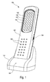
- the lighting device 100 includes, as shown in FIG. 1 , a housing 101, thirty-six LEDs 102 as lighting elements, and a plurality of power supply devices of different types (not shown in FIG. 1) integrated in the housing 101.
- the thirty six LEDs 102 are mounted in the housing 101 in a matrix.
- each of the plurality of power supply devices may be configured to supply the LEDs 102 with electrical energy. More specifically, each of the multiple power supplies may be user-selected to provide the LEDs 102 with electrical energy.
- the housing 101 can be removed from the receiving tray 103, e.g. when the lighting device 100 is fully charged or can be used independently of the base element 103. Accumulators may be provided in the receiving tray 103.
- a switch 104 is provided, with which a user can turn the LEDs 102 on or off.
- a charging lamp 105 indicates when the housing 101 is received in the receiving tray 103 to make electrical contact between these two elements, and therefore powering the LEDs 102 from the receiving tray 103 is enabled.
- Gripping aids 106 on an upper side of the housing 101 enable operation of the lighting device 100 with high user-friendliness.
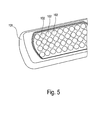
- FIG. 2 shows a modified lighting device 100 'in an operating state in which the housing 101 is removed from the receiving tray 103.
- two electrical contacting elements 107 are provided, which upon receiving the lighting device 100 'in the receiving tray 103 make electrical contact with correspondingly shaped and arranged contacting elements 109 (see FIG. 6) of the receiving tray 103 and thus supplying the housing 101 and allow the LEDs 102 contained therein with electrical energy.
- the embodiment according to FIG. 2 differs from that according to FIG. 1 in that 60 LEDs 102 'are provided instead of 36 LEDs 102. As a result, a particularly high luminosity can be achieved.
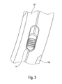
- FIG. 3 shows a side view of the housing 101 of the lighting device 100 of FIG. 1, in which the switch 104 is clearly visible. Further, on a rear side of the housing 101, a cover plate 108 can be seen, which can be removed to insert batteries into the handpiece 101.
- Fig. 4 shows a rear view of the housing 101 in an operating state in which the cover plate 108 is removed. A user may thereby insert batteries 109 into the handpiece 101 to allow operation of the handpiece independently of the charging shell 103 with battery 109 energy.
- FIG 6 shows an overall view of the components of the lighting device 100.
- the receiving tray 103 is connected via a removable connecting cable 111 with a power plug 110 for connection to a public power grid.
- a receiving portion of the receiving tray 103 for receiving the housing 101 contacting elements 109 are provided which are operable together with the contacting elements 107 of the handpiece 101.
- a suspension hook 112 is provided foldable out of or in the housing 101, wherein the receiving hook 112 can be conveniently stowed at a corresponding Auf originallyung 113 at the back of the housing 101.
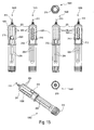
- FIG. 7 and FIG. 8 a lighting device 200 according to another exemplary embodiment of the invention will be described.
- the lighting device 200 includes, as shown in Fig. 7 , a housing 201 and a plurality of lighting elements.
- First lighting elements are LEDs 202 housed in a first housing section 203, more specifically, at an upper end portion of the first housing section 203.
- Second lighting elements are formed by an energy saving lamp 204 housed in a second housing section 205.
- the energy-saving lamp 204 can be used interchangeably in the housing section 205.
- a shutter 206 is provided to define a radiation direction of the light of the energy saving tube 204.
- the lighting device 200 includes several power supply devices of different types: In the first housing section 203, disposable batteries or rechargeable batteries are provided to keep the LEDs 202 in an operating state to be able to illuminate, in which the first housing portion 203 is unscrewed from the second housing portion 205.
- Rechargeable batteries or disposable batteries may also be provided in the second housing section 205, or the second housing section 205 may also be supplied with energy by means of an electrical cable (not shown in FIG. 7) through a power supply.
- An external thread 207 at the lower end portion of the first housing part 203 may be screwed with an internal thread 215 at an upper end portion of the second housing portion 205 to operate the lighting device 200.
- a fold-out hook 208 Attached to the upper end portion of the first housing portion 203 is a fold-out hook 208 which can be opened to secure the upper housing portion 203 or the bolted lighting device 200 to a mating piece.
- the energy efficient lamp 204 radiates substantially orthogonal thereto, but limited in space by the optional bezel 206.
- Profiles 218 on the first housing portion 203 and 209 on the second housing portion 205 provide a gripping, flexible and easy manageable screwing and holding the lighting device 200.
- An off-switch 210 makes it possible to turn on or off the power-saving lamp 204 of the lamp 200.
- An off switch 217 allows the LEDs 202 of the lamp 200 to be turned on or off.
- the housing sections 203, 205 are shown in a screwed-off operating state. Furthermore, a first magnetic fastening element 211 for fastening the first housing section 203 to a metallic surface is shown. Further, in a second housing portion 205, a second magnetic fastener 212 for attachment to a metallic surface is shown. The second housing section 205 is connected via an electrical cable 213 to a plug 214 for plugging into a public power grid.
- FIG. 9 shows different views of the charging tray 103 as described with reference to FIGS. 1 and 6.
- a front view 900, a right view 910, a rear view 920, a left view 930, a bottom view 940, and a top view 950 are shown in FIG.
- a rear power connection 901 can be seen in the rear view 920.
- a side power connection 902 can be seen in the left-side view 930.
- rubber elements 903 are seen in the bottom view 940 to avoid slippage of the charging tray 103 on a substrate.
- FIG. 10 different views of a wall holder will be described, which can be mounted on a wall, and into which a lighting device 100 or 100 'can be inserted in order to be stored or operated in the inserted state.
- FIG. 10 shows a front view 1000, a right view 1010, a rear view 1020, a left view 1030, a bottom view 1040, and a top view 1050.
- FIG. 10 is formed from a holding part 1001 and a fastening part 1002.
- the fastening part 1002 and the holding part 1001 together form a receptacle 1003, in which a hand-held device 100, 100 'can be accommodated and can thus be securely and safely stored.
- mounting holes 1004 the wall mount of Figure 10 can be secured to a wall using two screws.
- the dimensioning and the spacing of the elements 1001, 1002 can be dimensioned so that the hand-held device 100, 100 'can be inserted under slight pressure into the wall holder, so that the hand-held device 100, 100' is reliably protected from falling out.
- the use of the lighting device 100, 100 ' is realized user-friendly, since the LEDs 102, 102' remain uncovered by this construction and can thus develop their full luminosity. Furthermore, the switch 104 can be actuated without having to remove the handset 100, 100 'from the wall mount of FIG. 10.
- FIG. 11 shows different views of the lighting device 100 'from FIG. 2 as well as various accessory components.
- a view 1100 shows the lighting device 100 'in an operating state in which it is plugged into a receiving tray 103.
- a view 1110 shows the lighting device 100 'in an operating state in which it is taken out of the charging tray 103.
- a view 1120 shows the charging tray 103 without lighting device 100 '.
- a view 1130 shows the wall holder from FIG. 10 in an operating state in which the lighting device 100 'is not inserted therein.
- the view 1140 shows a 12 volt plug 1140 for connection to a motor vehicle. This contains a plug-in element 1103 for insertion into a cigarette lighter of a conventional motor vehicle.
- connection cable 1104, a spiral cable section 1105 and a plug-in section 1106 are shown, which can be plugged into the charging tray 103, for example in a lateral connection 902 or in a rear terminal 901, as shown in Fig. 9.
- the view 1150 shows a power adapter 1150 for plugging into a power grid and into terminals of a charging cradle.
- FIGS. 1, 2 to 6 shows views 1200 to 1250 of components for a 36 LED work lamp or accessory therefor, so that reference is made to FIGS. 1, 2 to 6 in this respect.
- a view 1200 shows the lighting device 100 in an operating state in which it is accommodated in a charging tray 103.
- a view 1210 shows the lighting device 100 in an operating state in which the lighting device 100 is removed from the charging tray 103.
- a view 1220 shows the charging tray 103 without the lighting device 100.
- a view 1230 shows a wall holder, similar to that shown in FIG. The 12 volt plug for a car from view 1240 and the power adapter from view 1250 correspond to the corresponding views 1140 and 1150 of FIG. 11.
- FIG. 13 shows different views of the illumination device 100 'from FIG. 2.
- FIG. 13 shows a front view 1300, a right side view 1310, a rear view 1320, a left side view 1330, a bottom view 1340, and a top view 1350.
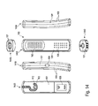
- FIG. 14 a front view 1400, a right side view 1410, a rear view 1420, a left side view 1430, a bottom view 1440, and a top view 1450 are shown.
- FIG. 15 shows different views of the illumination device 200 from FIG. 7 and FIG. 8 with the first housing section 203 unscrewed.
- FIG. 15 shows a front view 1500, a right view 1510, a rear view 1520, a left view 1530, a bottom view 1540, a top view 1550 and a spatial view 1560.
- Raised handle profiles 1501 are also shown.
- FIG. 16 shows different views of the illumination device 200 from FIG. 7 and FIG. 8 with the first housing section 203 screwed on.
- FIG. 16 shows a front view 1600, a right view 1610, a back view 1620, a left view 1630, a bottom view 1640, a top view 1650, and a perspective view 1660.
Applications Claiming Priority (1)
| Application Number | Priority Date | Filing Date | Title |
|---|---|---|---|
| US75364105P | 2005-12-23 | 2005-12-23 |
Publications (1)
| Publication Number | Publication Date |
|---|---|
| EP1801488A1 true EP1801488A1 (fr) | 2007-06-27 |
Family
ID=35781487
Family Applications (1)
| Application Number | Title | Priority Date | Filing Date |
|---|---|---|---|
| EP06001337A Withdrawn EP1801488A1 (fr) | 2005-12-23 | 2006-01-23 | Lampe |
Country Status (3)
| Country | Link |
|---|---|
| EP (1) | EP1801488A1 (fr) |
| DE (1) | DE202006000991U1 (fr) |
| WO (1) | WO2007079779A1 (fr) |
Families Citing this family (2)
| Publication number | Priority date | Publication date | Assignee | Title |
|---|---|---|---|---|
| DE102009004062A1 (de) * | 2009-01-05 | 2010-07-08 | Siemens Aktiengesellschaft | Verfahren zum Beleuchten von Gegenständen in einem Schaltschrank, transportable Lichtquelle sowie Schaltschrank |
| DE102012204840A1 (de) * | 2012-03-27 | 2013-10-02 | Osram Gmbh | LED-Leuchte |
Citations (9)
| Publication number | Priority date | Publication date | Assignee | Title |
|---|---|---|---|---|
| DE8612312U1 (de) * | 1986-05-05 | 1986-07-03 | Chou, An-Chuan, Tainan | Beleuchtungsgerät |
| GB2330404A (en) * | 1997-10-17 | 1999-04-21 | Alliance Ind Co Limited | Lighting device comprising two engageable lighting means |
| US6260985B1 (en) * | 1999-07-23 | 2001-07-17 | Noel E. Zeller | Multipurpose portable electric lighting apparatus |
| WO2002003761A1 (fr) * | 2000-07-03 | 2002-01-10 | Facom (Societe Anonyme) | Dispositif mobile d'eclairage |
| DE10150941A1 (de) * | 2001-10-16 | 2003-04-30 | Rainer Nackenhorst | Mobile Beleuchtungseinrichtung und Akkueinheit hierfür |
| US20050030737A1 (en) * | 2003-08-04 | 2005-02-10 | Chen Hsiu Chin | Multifunction warning device |
| US6857756B2 (en) * | 2001-04-11 | 2005-02-22 | General Manufacturing, Inc. | LED work light |
| US20050225968A1 (en) * | 2004-03-31 | 2005-10-13 | Hatherill Richard A | Work light |
| EP1607678A2 (fr) * | 2004-06-15 | 2005-12-21 | Premier Elektronik GmbH | Lampe avec des diodes électroluminescentes pour produire un faisceau large ou un faisceau ponctuel |
Family Cites Families (7)
| Publication number | Priority date | Publication date | Assignee | Title |
|---|---|---|---|---|
| CA2097982A1 (fr) * | 1993-06-08 | 1994-12-09 | Hsiang-Ta Cheng | Appareil d'eclairage a usages multiples |
| DE29809282U1 (de) * | 1998-05-22 | 1998-07-23 | Komos Gmbh Komponenten Module | Modulares Notleuchten System |
| DE20001901U1 (de) * | 2000-02-03 | 2000-06-21 | Liao Chun Chi | Multifunktionale Beleuchtungsvorrichtung |
| FR2826706B1 (fr) * | 2001-07-02 | 2004-01-30 | Facom | Dispositif mobile d'eclairage |
| DE10316031A1 (de) * | 2003-04-07 | 2004-11-11 | R. Stahl Schaltgeräte GmbH | Handscheinwerfer |
| DE20320048U1 (de) * | 2003-12-24 | 2004-03-18 | Hnc Import-Export & Vertriebs Ag | Taschenlampe |
| DE202004011722U1 (de) * | 2004-07-27 | 2004-12-09 | Shih Sanyo Enterprise Co., Ltd. | Taschenlampe mit einer wasserdichten Ladevorrichtung |
-
2006
- 2006-01-23 WO PCT/EP2006/000556 patent/WO2007079779A1/fr active Application Filing
- 2006-01-23 DE DE202006000991U patent/DE202006000991U1/de not_active Expired - Lifetime
- 2006-01-23 EP EP06001337A patent/EP1801488A1/fr not_active Withdrawn
Patent Citations (9)
| Publication number | Priority date | Publication date | Assignee | Title |
|---|---|---|---|---|
| DE8612312U1 (de) * | 1986-05-05 | 1986-07-03 | Chou, An-Chuan, Tainan | Beleuchtungsgerät |
| GB2330404A (en) * | 1997-10-17 | 1999-04-21 | Alliance Ind Co Limited | Lighting device comprising two engageable lighting means |
| US6260985B1 (en) * | 1999-07-23 | 2001-07-17 | Noel E. Zeller | Multipurpose portable electric lighting apparatus |
| WO2002003761A1 (fr) * | 2000-07-03 | 2002-01-10 | Facom (Societe Anonyme) | Dispositif mobile d'eclairage |
| US6857756B2 (en) * | 2001-04-11 | 2005-02-22 | General Manufacturing, Inc. | LED work light |
| DE10150941A1 (de) * | 2001-10-16 | 2003-04-30 | Rainer Nackenhorst | Mobile Beleuchtungseinrichtung und Akkueinheit hierfür |
| US20050030737A1 (en) * | 2003-08-04 | 2005-02-10 | Chen Hsiu Chin | Multifunction warning device |
| US20050225968A1 (en) * | 2004-03-31 | 2005-10-13 | Hatherill Richard A | Work light |
| EP1607678A2 (fr) * | 2004-06-15 | 2005-12-21 | Premier Elektronik GmbH | Lampe avec des diodes électroluminescentes pour produire un faisceau large ou un faisceau ponctuel |
Also Published As
| Publication number | Publication date |
|---|---|
| DE202006000991U1 (de) | 2006-05-24 |
| WO2007079779A1 (fr) | 2007-07-19 |
Similar Documents
| Publication | Publication Date | Title |
|---|---|---|
| DE69822637T2 (de) | Beleuchtungsvorrichtung für kraftbetriebene werkzeuge | |
| EP1670619B1 (fr) | Appareil de charge pour une visseuse à batterie | |
| US8083392B2 (en) | LED light has removable self-power LED unit(s) | |
| US20050047130A1 (en) | Picture light apparatus and method | |
| US11125418B2 (en) | Modular device with interchangeable torch lantern functionalities | |
| US8148917B2 (en) | Flashlight | |
| DE112009001556T5 (de) | Elektrische Anordnung mit einer Akkuladefunktion | |
| EP1715241A1 (fr) | Lampe portable avec systèmes de recharge manuel et secteur. | |
| US20100085743A1 (en) | Memorial cross | |
| US20190208760A1 (en) | Solar Powered LED Fly Trap | |
| EP2762764B1 (fr) | Unité d'éclairage mural | |
| EP1801488A1 (fr) | Lampe | |
| DE60123428T2 (de) | Tragbare beleuchtungseinrichtung | |
| DE10206418A1 (de) | Elektrische Kerzenleuchte | |
| EP3330592B1 (fr) | Éclairage transportable et portatif ainsi que procédé de commutation d'un tel éclairage | |
| WO2007076736A1 (fr) | Lampe | |
| DE202005004867U1 (de) | Leuchte für den Außenbereich sowie Leuchtenanordnung mit einer derartigen Leuchte | |
| US10317052B2 (en) | Battery powered LED set up stand | |
| US20180231192A1 (en) | Multi-functional detachable lighting apparatus and systems | |
| CN218441882U (zh) | 灯具 | |
| DE102017122217A1 (de) | Modulare Leuchte | |
| EP1632712B1 (fr) | Ensemble comprenant une pluralité de dispositifs électriques d'éclairage décoratifs | |
| DE3525698A1 (de) | Beleuchtungsvorrichtung fuer eine naehmaschine, zuschneidemaschine, knopflochnaehmaschine, knopfnaehmaschine od. dergl. fuer haeuslichen oder gewerblichen gebrauch | |
| AT414165B (de) | Leuchte | |
| WO2001001544A1 (fr) | Chargeur |
Legal Events
| Date | Code | Title | Description |
|---|---|---|---|
| PUAI | Public reference made under article 153(3) epc to a published international application that has entered the european phase |
Free format text: ORIGINAL CODE: 0009012 |
|
| AK | Designated contracting states |
Kind code of ref document: A1 Designated state(s): AT BE BG CH CY CZ DE DK EE ES FI FR GB GR HU IE IS IT LI LT LU LV MC NL PL PT RO SE SI SK TR |
|
| AX | Request for extension of the european patent |
Extension state: AL BA HR MK YU |
|
| AKX | Designation fees paid | ||
| STAA | Information on the status of an ep patent application or granted ep patent |
Free format text: STATUS: THE APPLICATION IS DEEMED TO BE WITHDRAWN |
|
| 18D | Application deemed to be withdrawn |
Effective date: 20071228 |
|
| REG | Reference to a national code |
Ref country code: DE Ref legal event code: 8566 |