EP1607588A2 - Ventiltrieb für eine Brennkraftmaschine - Google Patents
Ventiltrieb für eine Brennkraftmaschine Download PDFInfo
- Publication number
- EP1607588A2 EP1607588A2 EP05008708A EP05008708A EP1607588A2 EP 1607588 A2 EP1607588 A2 EP 1607588A2 EP 05008708 A EP05008708 A EP 05008708A EP 05008708 A EP05008708 A EP 05008708A EP 1607588 A2 EP1607588 A2 EP 1607588A2
- Authority
- EP
- European Patent Office
- Prior art keywords
- valve
- cam
- additional mass
- belt
- peripheral surface
- Prior art date
- Legal status (The legal status is an assumption and is not a legal conclusion. Google has not performed a legal analysis and makes no representation as to the accuracy of the status listed.)
- Granted
Links
Images


Classifications
-
- F—MECHANICAL ENGINEERING; LIGHTING; HEATING; WEAPONS; BLASTING
- F01—MACHINES OR ENGINES IN GENERAL; ENGINE PLANTS IN GENERAL; STEAM ENGINES
- F01L—CYCLICALLY OPERATING VALVES FOR MACHINES OR ENGINES
- F01L1/00—Valve-gear or valve arrangements, e.g. lift-valve gear
- F01L1/02—Valve drive
- F01L1/04—Valve drive by means of cams, camshafts, cam discs, eccentrics or the like
- F01L1/08—Shape of cams
-
- F—MECHANICAL ENGINEERING; LIGHTING; HEATING; WEAPONS; BLASTING
- F01—MACHINES OR ENGINES IN GENERAL; ENGINE PLANTS IN GENERAL; STEAM ENGINES
- F01L—CYCLICALLY OPERATING VALVES FOR MACHINES OR ENGINES
- F01L1/00—Valve-gear or valve arrangements, e.g. lift-valve gear
- F01L1/30—Valve-gear or valve arrangements, e.g. lift-valve gear characterised by the provision of positively opened and closed valves, i.e. desmodromic valves
Definitions
- the invention is based on a valve drive for an internal combustion engine, according to the preamble of claim 1.
- a generic valve train is shown in WO 01/12958 A1.
- This Valve gear has a rotatable cam, around which a belt element is arranged, which is fixed, i. the cam turns inside of the wrapping element.
- a gas exchange valve At the belt element is about a suspension attached a gas exchange valve, which in a known manner with a valve seat interacts.
- the object of the invention is to optimize a valve train of the type mentioned.
- valve train which mentioned in claim 1
- Features includes.
- Further embodiments of the valve train are in the dependent claims specified.
- the advantages achieved by the invention are in a valvetrain therein too see that acceleration peaks of the gas exchange valve or the Strapping be avoided or at least reduced.
- the acceleration peaks are advantageously prevented from causing the Wrap around the cam peripheral surface with high acceleration causing on the one hand damage to the cam peripheral surface and / or on the Entanglement element and on the other hand an excessive noise be avoided.
- the gas exchange valve suspended from the belt is, when accelerating the valve in the opening direction, the wrapper Lift off the cam peripheral surface in the area of the valve suspension. During this designated as free flight phase phase, the gas exchange valve is only passed through the belt. With a further rotation of the cam is the Gas exchange valve pulled back towards the closed position.
- the additional mass attached to the belt.
- a part of the wrapping element, in particular a link of a chain the additional mass itself form by comparing it with the other parts of the Umschlingungselements, in particular other members, having an increased mass.
- This increased mass can for example be provided by the fact that for the Member or role with the additional mass used a material with higher density becomes.
- this member with the additional mass can also be correspondingly larger than that other members are formed to have the increased mass. The same applies if the additional mass is arranged on a roller or sleeve of the chain.
- the wrapping element may also be in the form of a loop be formed, which - seen in the circumferential direction - is integrally formed. At the Loop can be attached to the additional mass.
- the closed or open loop Can be designed as fabric tape, rope or plastic ring. In the circumferential direction is the wrapping element is made in one piece, but it can be several layers exhibit.
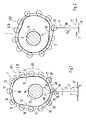
- valve drive 1 shown in Fig. 1 for a not shown here Internal combustion engine is a rotatable cam 2, a herumrow around the cam 2, with respect to the cam 2 fixed, but deflectable by the cam 2 Strapping element 3, a fastened to the belt element 3
- Gas exchange valve 4 is shown with a valve stem 5 and a valve plate 6, which Valve plate 6 cooperates with a valve seat 7.
- the cam 2 is in particular rotatably mounted on a rotatable camshaft 8. It comprises a base circle section 9, an eccentric section 10 and flanks 11 and 12 lying between the base circle section 9 and the eccentric section 10, of which - due to a predetermined direction of rotation 13 of the cam 2 - the flank 11 is defined as the opening flank 11 and the flank 12 as the closing flank 12.
- Base circle section 9, eccentric section 10 and flanks 11 and 12 form a cam peripheral surface 14 with a stroke contour which controls the stroke movement of the gas exchange valve 4.
- the gas exchange valve 4 will be in a closed position ST shown in FIG. 1 during a rotation of the cam 2, as long as the base circle section 9 acts on the gas exchange valve referred to hereinafter merely as a valve 4.
- the opening edge 11 of the stroke contour will initially move the valve 4 into a partial open position TT shown in FIG. 2, which here with a second rotational position DT2 of the cam 2 corresponds.
- the valve 4 is moved to the position shown in Fig. 3 complete open position VT, which is achieved at a third rotational position DT3 of the cam 2.
- the valve 4 is moved by the stroke contour of the cam 2 in the opening direction OR with an opening acceleration a o and lifted off the valve seat 7.
- the circumferentially executed and closed belt 3 is in Circumferential direction UR substantially inextensible and in the first embodiment 1 to 4 composed of a plurality of juxtaposed links 15, which are articulated in joint axes 16, so that the Umschlingungselement 3 to the stroke contour of the cam peripheral surface 14 as far as possible can create.
- the hinge axes 16 thus extend parallel to the extension of the Camshaft 8.
- the Belt element 3 can be used as chain 18, in particular roller chain or sleeve chain, be executed.
- the valve 4 is pivotally connected to the belt 3 in one Suspension 19 is connected to a pivot axis 20, wherein the pivot axis 20 - as the hinge axes 16 - parallel to the camshaft 8, so that the valve 4 in Double arrow 21 is pivotable.
- the pivot axis 20 and the hinge axis 16 at a hereinafter referred to as tap element 22 Roll 17 together.
- it can also be a holder not shown here with the Wrap member 3 may be connected to the tapping member 22 on which holder the valve 4 is pivotally hinged.
- the tapping element 22 follows the Cam peripheral surface 14, when the cam 2 rotates, and the tap element 22nd transmits the resulting stroke to the valve 4, which on the above described movement in the opening direction OR or closing direction SR performs.
- the circumferential length of the belt element 3 measured in the circumferential direction UR is slightly larger than the circumference measured in the same circumferential direction UR Cam 2 on the cam peripheral surface 14, so that between the cam peripheral surface 14th and wrapping element 3 a certain, in Figs. 2 to 3 exaggerated Game SP, whereby one or more rollers 17 from the cam peripheral surface 14 can take off.
- This game SP results, for example, from manufacturing tolerances the wrapping element 3 and / or the cam 2 and / or from a Length change of the belt 3 due to wear or aging and / or from the known polygon effect. However, it can also be one desired game SP be present to compensate for the known valve clearance to be able to. If the tapping element 22 follows the cam peripheral surface 14, this turns into a ideal movement (valve lift) of the valve 4 in the opening direction OR and closing direction.
- the picking element 22 lifts off the cam peripheral surface 14 when the picking element 22 and thus the valve 4 is moved in the opening direction OR with the opening acceleration a o .
- This lifting of the tapping element 22 causes a deviating from the ideal valve lift stroke and can already occur while the tapping element 22 is acted upon by the opening edge 11 and the eccentric portion 10 of the cam 2.
- the profile of the acceleration a v of the valve 4 over the angle of rotation NW of the camshaft 8 is shown in FIG. 6 in a solid line. After the opening acceleration a o from about a rotational angle of 150 ° of the camshaft 8, the pick-off element 22 lifts off the cam peripheral surface 14 until it is caught by the belt 3 after passing through the game SP.
- This phase of the movement of the valve 4 can also be referred to as a free-flight phase FP, which is approximately up to a rotation angle of about 240 ° of the camshaft. 8 stops.
- a free-flight phase FP the direction reversal of the movement of the valve 4 from the opening direction OR to the closing direction SR also takes place.
- the pick-off element 22 abruptly engages the cam peripheral surface 14, resulting in an acceleration peak value BS, which becomes clear in FIG. 6 by the dashed line segment.
- the Tap element 22 by at least one attached to the belt 3, accelerated additional mass 23 pulled back on the cam peripheral surface 14.
- the at least one additional mass 23 can by a roller 24 with respect to the other Roll 17 increased mass be provided. It would also be possible to have multiple roles Equip 17 with an additional mass 23.
- the additional mass 23 could additionally or alternatively attached to one of the links 15 or by a link 15 with opposite the other members 15 increased mass can be realized.
- the additional mass 23 is in An embodiment - seen in the circumferential direction UR - at a distance AB to the Abgriffselement 22 or arranged to the suspension 19 and is - in the direction of rotation 13 - seen - the suspension 19 and the tapping element 22, preferably directly, arranged downstream, that is preferably arranged on the member 15 and / or on the roller 24, the / the tapping element 22 follows directly.
- additional masses 23 are distributed to several members 15 are attached.
- additional masses 23 is preferably the closest to Tap element 22 lying additional mass 23 is the largest and the other Additional masses are set lower, with more than two additional masses the other (s) Additional masses are further reduced.
- both roles 17 and also to equip members 15 with additional masses 23 could alternatively or additionally to the tapping element 22nd Subordinate additional mass 23 in a similar manner, a member 15 and / or a roller 17th be provided with an additional mass 23 '(Fig. 1), which role 17 or which member 15 the tapping element 22 and the suspension 19 - seen in the direction of rotation 13 - with Distance AB is arranged upstream, thereby possibly lifting the tapping element 22nd could be prevented or reduced.
- an additional mass force ZK (FIG. 4) directed away from the cam peripheral surface 14 is generated during acceleration of the additional mass 23 by the stroke contour of the cam, which - due to the inertia of mass - generates the roller 24 the additional mass 23 can lift off from the cam peripheral surface 14, which in the attached to the additional mass 23 members 15, the additional mass force ZK disintegrates into force components KT that tighten the wrap 3 and move the tapping element 22 with a contact force AK back to the cam peripheral surface 14.
- the tapping element 22 is again located on the cam peripheral surface 14 before the start of the closing contour a s caused by the stroke contour, and the previously described hard tapping of the tapping element 22 on the cam peripheral surface 14 remains or is at least reduced, as can be seen from the solid line in FIG. 6 shown acceleration curve a v of the valve 4 is apparent.
- the maximum speed of the valve train 1 and thus the occurring acceleration a v can be taken into account in the determination of the additional mass 23.
- the additional mass 23, which is partially arranged on the wrap element 3, is chosen to be smaller than the mass of the valve 4.
- a second embodiment shown in Fig. 5 is the Belting element 3 of the valve train 1 as a circumferential, flexible loop 25th executed, which - in the circumferential direction UR - preferably integrally formed, however can be made of several layers 26, 27 or only one layer 26 or 27.
- the loop 25 is - in an analogous manner to the embodiment of FIG. 1 to 4 - with an additional mass 23 provided on the loop 25, for example, outside, attached or within the loop 25, for example, between two layers 26, 27 as Insert, can be attached.
- the same or the same effect Parts as shown in FIGS. 1 to 4 provided with the same reference numerals.
Landscapes
- Engineering & Computer Science (AREA)
- Mechanical Engineering (AREA)
- General Engineering & Computer Science (AREA)
- Valve Device For Special Equipments (AREA)
- Valve-Gear Or Valve Arrangements (AREA)
- Gears, Cams (AREA)
Abstract
Description
- Fig. 1 bis 4
- einen Ventiltrieb nach einem ersten Ausführungsbeispiel mit einem Nocken in unterschiedlichen Drehstellungen,
- Fig. 5
- einen Ventiltrieb nach einem zweiten Ausführungsbeispiel und
- Fig. 6
- ein Diagramm, in dem die Beschleunigung des Gaswechselventils über dem Drehwinkel der Nockenwelle angegeben ist.
Claims (8)
- Ventiltrieb für eine Brennkraftmaschine, mit einem drehbaren Nocken, einem um den Nocken angeordneten Umschlingungselement, einem Gaswechselventil und mit einer Aufhängung für das Gaswechselventil an dem Umschlingungselement, dadurch gekennzeichnet, dass das Umschlingungselement (3) - in Umfangsrichtung (UR) des Umschlingungselements (3) gesehen - mit Abstand (AB) zu der Aufhängung (19) partiell eine Zusatzmasse (23) aufweist.
- Ventiltrieb nach Anspruch 1, dadurch gekennzeichnet, dass die Zusatzmasse (23) - in Drehrichtung (13) des Nockens (2) gesehen - der Aufhängung (19) mit Abstand (AB) vor - und/oder nachgeordnet ist.
- Ventiltrieb nach Anspruch 1, dadurch gekennzeichnet, dass das Umschlingungselement (3) in Umfangsrichtung (UR) im wesentlichen undehnbar ausgeführt ist.
- Ventiltrieb nach Anspruch 1 oder 2, dadurch gekennzeichnet, dass die Zusatzmasse (23) an dem Umschlingungselement (3) befestigt ist.
- Ventiltrieb nach Anspruch 1, 2 oder 3, dadurch gekennzeichnet, dass das Umschlingungselement (3) aus mehreren beweglich aneinander gereihten Gliedern (15) zusammengesetzt ist, und dass die Zusatzmasse (23) durch eines der Glieder (15) gebildet ist, das gegenüber den anderen Gliedern eine erhöhte Masse aufweist.
- Ventiltrieb nach Anspruch 4, dadurch gekennzeichnet, dass zumindest ein Glied (15) eine Rolle (17, 24) oder Hülse aufweist, die sich auf der Umfangsfläche (14) des Nockens (2) abstützt, und dass die Rolle (24) oder Hülse die Zusatzmasse (23) aufweist.
- Ventiltrieb nach Anspruch 1, 5 oder 6, dadurch gekennzeichnet, dass das Umschlingungselement (3) als Kette (18) ausgebildet ist.
- Ventiltrieb nach einem der Ansprüche 1 bis 4, dadurch gekennzeichnet, dass das Umschlingungselement (3) als - in Umfangsrichtung (UR) gesehen - einstückige Schlaufe (25) ausgebildet ist, welche Schlaufe (25) die Zusatzmasse (23) aufweist.
Applications Claiming Priority (2)
| Application Number | Priority Date | Filing Date | Title |
|---|---|---|---|
| DE200410029621 DE102004029621B4 (de) | 2004-06-18 | 2004-06-18 | Ventiltrieb für eine Brennkraftmaschine |
| DE102004029621 | 2004-06-18 |
Publications (3)
| Publication Number | Publication Date |
|---|---|
| EP1607588A2 true EP1607588A2 (de) | 2005-12-21 |
| EP1607588A3 EP1607588A3 (de) | 2008-08-20 |
| EP1607588B1 EP1607588B1 (de) | 2012-04-11 |
Family
ID=35045144
Family Applications (1)
| Application Number | Title | Priority Date | Filing Date |
|---|---|---|---|
| EP20050008708 Expired - Lifetime EP1607588B1 (de) | 2004-06-18 | 2005-04-21 | Ventiltrieb für eine Brennkraftmaschine |
Country Status (2)
| Country | Link |
|---|---|
| EP (1) | EP1607588B1 (de) |
| DE (1) | DE102004029621B4 (de) |
Citations (1)
| Publication number | Priority date | Publication date | Assignee | Title |
|---|---|---|---|---|
| WO2001012958A1 (de) | 1999-08-12 | 2001-02-22 | Stefan Battlogg | Ventiltrieb, insbesondere für brennkraftmaschinen von kraftfahrzeugen |
Family Cites Families (6)
| Publication number | Priority date | Publication date | Assignee | Title |
|---|---|---|---|---|
| DE3700715A1 (de) * | 1986-01-22 | 1987-07-23 | Volkswagen Ag | Zwangssteuerung fuer ein ventil |
| US20020073948A1 (en) * | 1998-06-16 | 2002-06-20 | Stefan Battlogg | Valve mechanism, in particular for internal combustion engines |
| WO2002081871A1 (de) * | 2001-04-09 | 2002-10-17 | Stefan Battlogg | Desmodromische ventiltrieb |
| DE20320710U1 (de) * | 2002-03-28 | 2005-02-10 | Battlogg, Stefan | Vorrichtung zur Umwandlung einer Drehbewegung in eine hin- und hergehende Bewegung |
| DE10225620A1 (de) * | 2002-06-07 | 2003-12-24 | Daimler Chrysler Ag | Zwangsgeführter Ventiltrieb |
| DE502005002015D1 (de) * | 2004-03-26 | 2008-01-03 | Stefan Battlogg | Desmodromischer Ventiltrieb |
-
2004
- 2004-06-18 DE DE200410029621 patent/DE102004029621B4/de not_active Expired - Fee Related
-
2005
- 2005-04-21 EP EP20050008708 patent/EP1607588B1/de not_active Expired - Lifetime
Patent Citations (1)
| Publication number | Priority date | Publication date | Assignee | Title |
|---|---|---|---|---|
| WO2001012958A1 (de) | 1999-08-12 | 2001-02-22 | Stefan Battlogg | Ventiltrieb, insbesondere für brennkraftmaschinen von kraftfahrzeugen |
Also Published As
| Publication number | Publication date |
|---|---|
| EP1607588B1 (de) | 2012-04-11 |
| DE102004029621A1 (de) | 2006-01-12 |
| EP1607588A3 (de) | 2008-08-20 |
| DE102004029621B4 (de) | 2006-09-07 |
Similar Documents
| Publication | Publication Date | Title |
|---|---|---|
| DE69921153T2 (de) | Variable ventilsteuerungseinrichtung | |
| DE3014005C2 (de) | ||
| DE60028951T2 (de) | Hebelanordnung für gaseinlass- und auslassventile zum verändern des ventilhubs und teilen bei positiver leistung | |
| DE10063997C2 (de) | Variable Ventilbetätigungsvorrichtung für Motoren mit innerer Verbrennung | |
| DE60308377T2 (de) | Hubverstellungseinrichtung für motorventile | |
| DE69708757T2 (de) | Hydraulischer Ventilstössel | |
| DE102008015197B4 (de) | Ventilmechanismus eines Motors | |
| EP1206628A1 (de) | Ventiltrieb, insbesondere für brennkraftmaschinen | |
| WO1993017227A1 (de) | Ventilbetätigungsmechanismus für eine brennkraftmaschine | |
| DE3705128C2 (de) | ||
| EP1375847A2 (de) | Einrichtung zur variablen Betätigung von Ventilen | |
| DE4135257C2 (de) | Vorrichtung zur Betätigung der Ventile in Verbrennungsmotoren mittels umlaufender Nocken | |
| DE10235402A1 (de) | Schwenkhebel für einen hubvariablen Ventiltrieb | |
| WO2003083269A1 (de) | Vorrichtung zur umwandlung einer drehbewegung in eine hin- und hergehende bewegung | |
| EP1205643A1 (de) | Ventieltrieb für eine Verbrennungskraftmaschine | |
| DE20220138U1 (de) | Ventiltrieb mit Nocken zur variablen Betätigung von Ventilen für Verbrennungsmotoren | |
| DE102008027649A1 (de) | Ventilbetrieb für eine Brennkraftmaschine | |
| DE68921369T2 (de) | Ventilsteuervorrichtung für Brennkraftmaschinen. | |
| EP1607588B1 (de) | Ventiltrieb für eine Brennkraftmaschine | |
| DE102010055056A1 (de) | Ventiltrieb für Gaswechselventile mit unterschiedlichem Spiel zwischen Verzahnungen einer Grundnockenwelle und eines darauf verschiebbaren Nockenträgers | |
| DE10226300B4 (de) | Einrichtung zur variablen Betätigung von Ventilen mittels Nocken für Verbrennungsmotoren | |
| EP1608851A1 (de) | Vorrichtung zur variablen betätigung der gaswechselventile von verbrennungsmotoren und verfahren zum betreiben einer derartigen vorrichtung | |
| DE102008015218B4 (de) | Ventilmechanismus eines Motors | |
| DE10249187B4 (de) | Variabler Ventilmechanismus mit einem Unterstützungskraftaufbringabschnitt sowie Arbeitsverfahren dafür | |
| EP1619362B1 (de) | Ventiltrieb einer Brennkraftmaschine |
Legal Events
| Date | Code | Title | Description |
|---|---|---|---|
| PUAI | Public reference made under article 153(3) epc to a published international application that has entered the european phase |
Free format text: ORIGINAL CODE: 0009012 |
|
| AK | Designated contracting states |
Kind code of ref document: A2 Designated state(s): AT BE BG CH CY CZ DE DK EE ES FI FR GB GR HU IE IS IT LI LT LU MC NL PL PT RO SE SI SK TR |
|
| AX | Request for extension of the european patent |
Extension state: AL BA HR LV MK YU |
|
| RAP1 | Party data changed (applicant data changed or rights of an application transferred) |
Owner name: DR. ING. H.C. F. PORSCHE AKTIENGESELLSCHAFT |
|
| RAP1 | Party data changed (applicant data changed or rights of an application transferred) |
Owner name: DR. ING. H.C. F. PORSCHE AKTIENGESELLSCHAFT |
|
| PUAL | Search report despatched |
Free format text: ORIGINAL CODE: 0009013 |
|
| AK | Designated contracting states |
Kind code of ref document: A3 Designated state(s): AT BE BG CH CY CZ DE DK EE ES FI FR GB GR HU IE IS IT LI LT LU MC NL PL PT RO SE SI SK TR |
|
| AX | Request for extension of the european patent |
Extension state: AL BA HR LV MK YU |
|
| 17P | Request for examination filed |
Effective date: 20090220 |
|
| AKX | Designation fees paid |
Designated state(s): DE FR GB IT |
|
| 17Q | First examination report despatched |
Effective date: 20091208 |
|
| RAP1 | Party data changed (applicant data changed or rights of an application transferred) |
Owner name: DR. ING. H.C. F. PORSCHE AG |
|
| GRAP | Despatch of communication of intention to grant a patent |
Free format text: ORIGINAL CODE: EPIDOSNIGR1 |
|
| GRAS | Grant fee paid |
Free format text: ORIGINAL CODE: EPIDOSNIGR3 |
|
| GRAA | (expected) grant |
Free format text: ORIGINAL CODE: 0009210 |
|
| AK | Designated contracting states |
Kind code of ref document: B1 Designated state(s): DE FR GB IT |
|
| REG | Reference to a national code |
Ref country code: GB Ref legal event code: FG4D Free format text: NOT ENGLISH |
|
| REG | Reference to a national code |
Ref country code: DE Ref legal event code: R096 Ref document number: 502005012606 Country of ref document: DE Effective date: 20120606 |
|
| PLBE | No opposition filed within time limit |
Free format text: ORIGINAL CODE: 0009261 |
|
| STAA | Information on the status of an ep patent application or granted ep patent |
Free format text: STATUS: NO OPPOSITION FILED WITHIN TIME LIMIT |
|
| 26N | No opposition filed |
Effective date: 20130114 |
|
| REG | Reference to a national code |
Ref country code: DE Ref legal event code: R097 Ref document number: 502005012606 Country of ref document: DE Effective date: 20130114 |
|
| REG | Reference to a national code |
Ref country code: FR Ref legal event code: PLFP Year of fee payment: 12 |
|
| REG | Reference to a national code |
Ref country code: FR Ref legal event code: PLFP Year of fee payment: 13 |
|
| REG | Reference to a national code |
Ref country code: FR Ref legal event code: PLFP Year of fee payment: 14 |
|
| PGFP | Annual fee paid to national office [announced via postgrant information from national office to epo] |
Ref country code: DE Payment date: 20200402 Year of fee payment: 16 Ref country code: FR Payment date: 20200420 Year of fee payment: 16 |
|
| PGFP | Annual fee paid to national office [announced via postgrant information from national office to epo] |
Ref country code: GB Payment date: 20200427 Year of fee payment: 16 Ref country code: IT Payment date: 20200428 Year of fee payment: 16 |
|
| REG | Reference to a national code |
Ref country code: DE Ref legal event code: R119 Ref document number: 502005012606 Country of ref document: DE |
|
| GBPC | Gb: european patent ceased through non-payment of renewal fee |
Effective date: 20210421 |
|
| PG25 | Lapsed in a contracting state [announced via postgrant information from national office to epo] |
Ref country code: GB Free format text: LAPSE BECAUSE OF NON-PAYMENT OF DUE FEES Effective date: 20210421 Ref country code: FR Free format text: LAPSE BECAUSE OF NON-PAYMENT OF DUE FEES Effective date: 20210430 Ref country code: DE Free format text: LAPSE BECAUSE OF NON-PAYMENT OF DUE FEES Effective date: 20211103 |
|
| PG25 | Lapsed in a contracting state [announced via postgrant information from national office to epo] |
Ref country code: IT Free format text: LAPSE BECAUSE OF NON-PAYMENT OF DUE FEES Effective date: 20200421 |
|
| PG25 | Lapsed in a contracting state [announced via postgrant information from national office to epo] |
Ref country code: IT Free format text: LAPSE BECAUSE OF NON-PAYMENT OF DUE FEES Effective date: 20210421 |