EP1606498B1 - Exhaust system for lean burn ic engine including particulate filter and no sb x /sb absorbent - Google Patents
Exhaust system for lean burn ic engine including particulate filter and no sb x /sb absorbent Download PDFInfo
- Publication number
- EP1606498B1 EP1606498B1 EP04718332A EP04718332A EP1606498B1 EP 1606498 B1 EP1606498 B1 EP 1606498B1 EP 04718332 A EP04718332 A EP 04718332A EP 04718332 A EP04718332 A EP 04718332A EP 1606498 B1 EP1606498 B1 EP 1606498B1
- Authority
- EP
- European Patent Office
- Prior art keywords
- absorbent
- filter
- exhaust gas
- reductant
- lean
- Prior art date
- Legal status (The legal status is an assumption and is not a legal conclusion. Google has not performed a legal analysis and makes no representation as to the accuracy of the status listed.)
- Expired - Lifetime
Links
Images


Classifications
-
- B—PERFORMING OPERATIONS; TRANSPORTING
- B01—PHYSICAL OR CHEMICAL PROCESSES OR APPARATUS IN GENERAL
- B01J—CHEMICAL OR PHYSICAL PROCESSES, e.g. CATALYSIS OR COLLOID CHEMISTRY; THEIR RELEVANT APPARATUS
- B01J35/00—Catalysts, in general, characterised by their form or physical properties
- B01J35/20—Catalysts, in general, characterised by their form or physical properties characterised by their non-solid state
- B01J35/27—Catalysts, in general, characterised by their form or physical properties characterised by their non-solid state in a liquid or molten state
-
- F—MECHANICAL ENGINEERING; LIGHTING; HEATING; WEAPONS; BLASTING
- F01—MACHINES OR ENGINES IN GENERAL; ENGINE PLANTS IN GENERAL; STEAM ENGINES
- F01N—GAS-FLOW SILENCERS OR EXHAUST APPARATUS FOR MACHINES OR ENGINES IN GENERAL; GAS-FLOW SILENCERS OR EXHAUST APPARATUS FOR INTERNAL-COMBUSTION ENGINES
- F01N3/00—Exhaust or silencing apparatus having means for purifying, rendering innocuous, or otherwise treating exhaust
- F01N3/08—Exhaust or silencing apparatus having means for purifying, rendering innocuous, or otherwise treating exhaust for rendering innocuous
-
- B—PERFORMING OPERATIONS; TRANSPORTING
- B01—PHYSICAL OR CHEMICAL PROCESSES OR APPARATUS IN GENERAL
- B01D—SEPARATION
- B01D53/00—Separation of gases or vapours; Recovering vapours of volatile solvents from gases; Chemical or biological purification of waste gases, e.g. engine exhaust gases, smoke, fumes, flue gases, aerosols
- B01D53/34—Chemical or biological purification of waste gases
- B01D53/92—Chemical or biological purification of waste gases of engine exhaust gases
- B01D53/94—Chemical or biological purification of waste gases of engine exhaust gases by catalytic processes
- B01D53/9404—Removing only nitrogen compounds
- B01D53/9409—Nitrogen oxides
- B01D53/9413—Processes characterised by a specific catalyst
- B01D53/9422—Processes characterised by a specific catalyst for removing nitrogen oxides by NOx storage or reduction by cyclic switching between lean and rich exhaust gases (LNT, NSC, NSR)
-
- B—PERFORMING OPERATIONS; TRANSPORTING
- B01—PHYSICAL OR CHEMICAL PROCESSES OR APPARATUS IN GENERAL
- B01D—SEPARATION
- B01D53/00—Separation of gases or vapours; Recovering vapours of volatile solvents from gases; Chemical or biological purification of waste gases, e.g. engine exhaust gases, smoke, fumes, flue gases, aerosols
- B01D53/34—Chemical or biological purification of waste gases
- B01D53/92—Chemical or biological purification of waste gases of engine exhaust gases
- B01D53/94—Chemical or biological purification of waste gases of engine exhaust gases by catalytic processes
- B01D53/9404—Removing only nitrogen compounds
- B01D53/9409—Nitrogen oxides
- B01D53/9431—Processes characterised by a specific device
-
- B—PERFORMING OPERATIONS; TRANSPORTING
- B01—PHYSICAL OR CHEMICAL PROCESSES OR APPARATUS IN GENERAL
- B01D—SEPARATION
- B01D53/00—Separation of gases or vapours; Recovering vapours of volatile solvents from gases; Chemical or biological purification of waste gases, e.g. engine exhaust gases, smoke, fumes, flue gases, aerosols
- B01D53/34—Chemical or biological purification of waste gases
- B01D53/92—Chemical or biological purification of waste gases of engine exhaust gases
- B01D53/94—Chemical or biological purification of waste gases of engine exhaust gases by catalytic processes
- B01D53/9459—Removing one or more of nitrogen oxides, carbon monoxide, or hydrocarbons by multiple successive catalytic functions; systems with more than one different function, e.g. zone coated catalysts
- B01D53/9477—Removing one or more of nitrogen oxides, carbon monoxide, or hydrocarbons by multiple successive catalytic functions; systems with more than one different function, e.g. zone coated catalysts with catalysts positioned on separate bricks, e.g. exhaust systems
-
- B—PERFORMING OPERATIONS; TRANSPORTING
- B01—PHYSICAL OR CHEMICAL PROCESSES OR APPARATUS IN GENERAL
- B01J—CHEMICAL OR PHYSICAL PROCESSES, e.g. CATALYSIS OR COLLOID CHEMISTRY; THEIR RELEVANT APPARATUS
- B01J23/00—Catalysts comprising metals or metal oxides or hydroxides, not provided for in group B01J21/00
- B01J23/16—Catalysts comprising metals or metal oxides or hydroxides, not provided for in group B01J21/00 of arsenic, antimony, bismuth, vanadium, niobium, tantalum, polonium, chromium, molybdenum, tungsten, manganese, technetium or rhenium
- B01J23/20—Vanadium, niobium or tantalum
- B01J23/22—Vanadium
-
- B—PERFORMING OPERATIONS; TRANSPORTING
- B01—PHYSICAL OR CHEMICAL PROCESSES OR APPARATUS IN GENERAL
- B01J—CHEMICAL OR PHYSICAL PROCESSES, e.g. CATALYSIS OR COLLOID CHEMISTRY; THEIR RELEVANT APPARATUS
- B01J23/00—Catalysts comprising metals or metal oxides or hydroxides, not provided for in group B01J21/00
- B01J23/16—Catalysts comprising metals or metal oxides or hydroxides, not provided for in group B01J21/00 of arsenic, antimony, bismuth, vanadium, niobium, tantalum, polonium, chromium, molybdenum, tungsten, manganese, technetium or rhenium
- B01J23/24—Chromium, molybdenum or tungsten
-
- B—PERFORMING OPERATIONS; TRANSPORTING
- B01—PHYSICAL OR CHEMICAL PROCESSES OR APPARATUS IN GENERAL
- B01J—CHEMICAL OR PHYSICAL PROCESSES, e.g. CATALYSIS OR COLLOID CHEMISTRY; THEIR RELEVANT APPARATUS
- B01J35/00—Catalysts, in general, characterised by their form or physical properties
- B01J35/19—Catalysts containing parts with different compositions
-
- F—MECHANICAL ENGINEERING; LIGHTING; HEATING; WEAPONS; BLASTING
- F01—MACHINES OR ENGINES IN GENERAL; ENGINE PLANTS IN GENERAL; STEAM ENGINES
- F01N—GAS-FLOW SILENCERS OR EXHAUST APPARATUS FOR MACHINES OR ENGINES IN GENERAL; GAS-FLOW SILENCERS OR EXHAUST APPARATUS FOR INTERNAL-COMBUSTION ENGINES
- F01N13/00—Exhaust or silencing apparatus characterised by constructional features
- F01N13/009—Exhaust or silencing apparatus characterised by constructional features having two or more separate purifying devices arranged in series
- F01N13/0093—Exhaust or silencing apparatus characterised by constructional features having two or more separate purifying devices arranged in series the purifying devices are of the same type
-
- F—MECHANICAL ENGINEERING; LIGHTING; HEATING; WEAPONS; BLASTING
- F01—MACHINES OR ENGINES IN GENERAL; ENGINE PLANTS IN GENERAL; STEAM ENGINES
- F01N—GAS-FLOW SILENCERS OR EXHAUST APPARATUS FOR MACHINES OR ENGINES IN GENERAL; GAS-FLOW SILENCERS OR EXHAUST APPARATUS FOR INTERNAL-COMBUSTION ENGINES
- F01N3/00—Exhaust or silencing apparatus having means for purifying, rendering innocuous, or otherwise treating exhaust
- F01N3/02—Exhaust or silencing apparatus having means for purifying, rendering innocuous, or otherwise treating exhaust for cooling, or for removing solid constituents of, exhaust
- F01N3/021—Exhaust or silencing apparatus having means for purifying, rendering innocuous, or otherwise treating exhaust for cooling, or for removing solid constituents of, exhaust by means of filters
- F01N3/023—Exhaust or silencing apparatus having means for purifying, rendering innocuous, or otherwise treating exhaust for cooling, or for removing solid constituents of, exhaust by means of filters using means for regenerating the filters, e.g. by burning trapped particles
- F01N3/0231—Exhaust or silencing apparatus having means for purifying, rendering innocuous, or otherwise treating exhaust for cooling, or for removing solid constituents of, exhaust by means of filters using means for regenerating the filters, e.g. by burning trapped particles using special exhaust apparatus upstream of the filter for producing nitrogen dioxide, e.g. for continuous filter regeneration systems [CRT]
-
- F—MECHANICAL ENGINEERING; LIGHTING; HEATING; WEAPONS; BLASTING
- F01—MACHINES OR ENGINES IN GENERAL; ENGINE PLANTS IN GENERAL; STEAM ENGINES
- F01N—GAS-FLOW SILENCERS OR EXHAUST APPARATUS FOR MACHINES OR ENGINES IN GENERAL; GAS-FLOW SILENCERS OR EXHAUST APPARATUS FOR INTERNAL-COMBUSTION ENGINES
- F01N3/00—Exhaust or silencing apparatus having means for purifying, rendering innocuous, or otherwise treating exhaust
- F01N3/02—Exhaust or silencing apparatus having means for purifying, rendering innocuous, or otherwise treating exhaust for cooling, or for removing solid constituents of, exhaust
- F01N3/021—Exhaust or silencing apparatus having means for purifying, rendering innocuous, or otherwise treating exhaust for cooling, or for removing solid constituents of, exhaust by means of filters
- F01N3/023—Exhaust or silencing apparatus having means for purifying, rendering innocuous, or otherwise treating exhaust for cooling, or for removing solid constituents of, exhaust by means of filters using means for regenerating the filters, e.g. by burning trapped particles
- F01N3/025—Exhaust or silencing apparatus having means for purifying, rendering innocuous, or otherwise treating exhaust for cooling, or for removing solid constituents of, exhaust by means of filters using means for regenerating the filters, e.g. by burning trapped particles using fuel burner or by adding fuel to exhaust
- F01N3/0253—Exhaust or silencing apparatus having means for purifying, rendering innocuous, or otherwise treating exhaust for cooling, or for removing solid constituents of, exhaust by means of filters using means for regenerating the filters, e.g. by burning trapped particles using fuel burner or by adding fuel to exhaust adding fuel to exhaust gases
-
- F—MECHANICAL ENGINEERING; LIGHTING; HEATING; WEAPONS; BLASTING
- F01—MACHINES OR ENGINES IN GENERAL; ENGINE PLANTS IN GENERAL; STEAM ENGINES
- F01N—GAS-FLOW SILENCERS OR EXHAUST APPARATUS FOR MACHINES OR ENGINES IN GENERAL; GAS-FLOW SILENCERS OR EXHAUST APPARATUS FOR INTERNAL-COMBUSTION ENGINES
- F01N3/00—Exhaust or silencing apparatus having means for purifying, rendering innocuous, or otherwise treating exhaust
- F01N3/02—Exhaust or silencing apparatus having means for purifying, rendering innocuous, or otherwise treating exhaust for cooling, or for removing solid constituents of, exhaust
- F01N3/021—Exhaust or silencing apparatus having means for purifying, rendering innocuous, or otherwise treating exhaust for cooling, or for removing solid constituents of, exhaust by means of filters
- F01N3/033—Exhaust or silencing apparatus having means for purifying, rendering innocuous, or otherwise treating exhaust for cooling, or for removing solid constituents of, exhaust by means of filters in combination with other devices
- F01N3/035—Exhaust or silencing apparatus having means for purifying, rendering innocuous, or otherwise treating exhaust for cooling, or for removing solid constituents of, exhaust by means of filters in combination with other devices with catalytic reactors
-
- F—MECHANICAL ENGINEERING; LIGHTING; HEATING; WEAPONS; BLASTING
- F01—MACHINES OR ENGINES IN GENERAL; ENGINE PLANTS IN GENERAL; STEAM ENGINES
- F01N—GAS-FLOW SILENCERS OR EXHAUST APPARATUS FOR MACHINES OR ENGINES IN GENERAL; GAS-FLOW SILENCERS OR EXHAUST APPARATUS FOR INTERNAL-COMBUSTION ENGINES
- F01N3/00—Exhaust or silencing apparatus having means for purifying, rendering innocuous, or otherwise treating exhaust
- F01N3/08—Exhaust or silencing apparatus having means for purifying, rendering innocuous, or otherwise treating exhaust for rendering innocuous
- F01N3/0807—Exhaust or silencing apparatus having means for purifying, rendering innocuous, or otherwise treating exhaust for rendering innocuous by using absorbents or adsorbents
- F01N3/0821—Exhaust or silencing apparatus having means for purifying, rendering innocuous, or otherwise treating exhaust for rendering innocuous by using absorbents or adsorbents combined with particulate filter
-
- F—MECHANICAL ENGINEERING; LIGHTING; HEATING; WEAPONS; BLASTING
- F01—MACHINES OR ENGINES IN GENERAL; ENGINE PLANTS IN GENERAL; STEAM ENGINES
- F01N—GAS-FLOW SILENCERS OR EXHAUST APPARATUS FOR MACHINES OR ENGINES IN GENERAL; GAS-FLOW SILENCERS OR EXHAUST APPARATUS FOR INTERNAL-COMBUSTION ENGINES
- F01N3/00—Exhaust or silencing apparatus having means for purifying, rendering innocuous, or otherwise treating exhaust
- F01N3/08—Exhaust or silencing apparatus having means for purifying, rendering innocuous, or otherwise treating exhaust for rendering innocuous
- F01N3/0807—Exhaust or silencing apparatus having means for purifying, rendering innocuous, or otherwise treating exhaust for rendering innocuous by using absorbents or adsorbents
- F01N3/0828—Exhaust or silencing apparatus having means for purifying, rendering innocuous, or otherwise treating exhaust for rendering innocuous by using absorbents or adsorbents characterised by the absorbed or adsorbed substances
- F01N3/0842—Nitrogen oxides
-
- B—PERFORMING OPERATIONS; TRANSPORTING
- B01—PHYSICAL OR CHEMICAL PROCESSES OR APPARATUS IN GENERAL
- B01D—SEPARATION
- B01D2255/00—Catalysts
- B01D2255/10—Noble metals or compounds thereof
- B01D2255/102—Platinum group metals
- B01D2255/1021—Platinum
-
- B—PERFORMING OPERATIONS; TRANSPORTING
- B01—PHYSICAL OR CHEMICAL PROCESSES OR APPARATUS IN GENERAL
- B01D—SEPARATION
- B01D2255/00—Catalysts
- B01D2255/10—Noble metals or compounds thereof
- B01D2255/102—Platinum group metals
- B01D2255/1025—Rhodium
-
- B—PERFORMING OPERATIONS; TRANSPORTING
- B01—PHYSICAL OR CHEMICAL PROCESSES OR APPARATUS IN GENERAL
- B01D—SEPARATION
- B01D2255/00—Catalysts
- B01D2255/20—Metals or compounds thereof
- B01D2255/202—Alkali metals
-
- B—PERFORMING OPERATIONS; TRANSPORTING
- B01—PHYSICAL OR CHEMICAL PROCESSES OR APPARATUS IN GENERAL
- B01D—SEPARATION
- B01D2255/00—Catalysts
- B01D2255/20—Metals or compounds thereof
- B01D2255/204—Alkaline earth metals
- B01D2255/2042—Barium
-
- B—PERFORMING OPERATIONS; TRANSPORTING
- B01—PHYSICAL OR CHEMICAL PROCESSES OR APPARATUS IN GENERAL
- B01D—SEPARATION
- B01D2255/00—Catalysts
- B01D2255/20—Metals or compounds thereof
- B01D2255/206—Rare earth metals
- B01D2255/2065—Cerium
-
- B—PERFORMING OPERATIONS; TRANSPORTING
- B01—PHYSICAL OR CHEMICAL PROCESSES OR APPARATUS IN GENERAL
- B01J—CHEMICAL OR PHYSICAL PROCESSES, e.g. CATALYSIS OR COLLOID CHEMISTRY; THEIR RELEVANT APPARATUS
- B01J35/00—Catalysts, in general, characterised by their form or physical properties
- B01J35/50—Catalysts, in general, characterised by their form or physical properties characterised by their shape or configuration
- B01J35/56—Foraminous structures having flow-through passages or channels, e.g. grids or three-dimensional monoliths
-
- F—MECHANICAL ENGINEERING; LIGHTING; HEATING; WEAPONS; BLASTING
- F01—MACHINES OR ENGINES IN GENERAL; ENGINE PLANTS IN GENERAL; STEAM ENGINES
- F01N—GAS-FLOW SILENCERS OR EXHAUST APPARATUS FOR MACHINES OR ENGINES IN GENERAL; GAS-FLOW SILENCERS OR EXHAUST APPARATUS FOR INTERNAL-COMBUSTION ENGINES
- F01N2610/00—Adding substances to exhaust gases
- F01N2610/02—Adding substances to exhaust gases the substance being ammonia or urea
-
- F—MECHANICAL ENGINEERING; LIGHTING; HEATING; WEAPONS; BLASTING
- F01—MACHINES OR ENGINES IN GENERAL; ENGINE PLANTS IN GENERAL; STEAM ENGINES
- F01N—GAS-FLOW SILENCERS OR EXHAUST APPARATUS FOR MACHINES OR ENGINES IN GENERAL; GAS-FLOW SILENCERS OR EXHAUST APPARATUS FOR INTERNAL-COMBUSTION ENGINES
- F01N2610/00—Adding substances to exhaust gases
- F01N2610/03—Adding substances to exhaust gases the substance being hydrocarbons, e.g. engine fuel
-
- F—MECHANICAL ENGINEERING; LIGHTING; HEATING; WEAPONS; BLASTING
- F01—MACHINES OR ENGINES IN GENERAL; ENGINE PLANTS IN GENERAL; STEAM ENGINES
- F01N—GAS-FLOW SILENCERS OR EXHAUST APPARATUS FOR MACHINES OR ENGINES IN GENERAL; GAS-FLOW SILENCERS OR EXHAUST APPARATUS FOR INTERNAL-COMBUSTION ENGINES
- F01N3/00—Exhaust or silencing apparatus having means for purifying, rendering innocuous, or otherwise treating exhaust
- F01N3/08—Exhaust or silencing apparatus having means for purifying, rendering innocuous, or otherwise treating exhaust for rendering innocuous
- F01N3/10—Exhaust or silencing apparatus having means for purifying, rendering innocuous, or otherwise treating exhaust for rendering innocuous by thermal or catalytic conversion of noxious components of exhaust
- F01N3/18—Exhaust or silencing apparatus having means for purifying, rendering innocuous, or otherwise treating exhaust for rendering innocuous by thermal or catalytic conversion of noxious components of exhaust characterised by methods of operation; Control
- F01N3/22—Control of additional air supply only, e.g. using by-passes or variable air pump drives
-
- F—MECHANICAL ENGINEERING; LIGHTING; HEATING; WEAPONS; BLASTING
- F01—MACHINES OR ENGINES IN GENERAL; ENGINE PLANTS IN GENERAL; STEAM ENGINES
- F01N—GAS-FLOW SILENCERS OR EXHAUST APPARATUS FOR MACHINES OR ENGINES IN GENERAL; GAS-FLOW SILENCERS OR EXHAUST APPARATUS FOR INTERNAL-COMBUSTION ENGINES
- F01N3/00—Exhaust or silencing apparatus having means for purifying, rendering innocuous, or otherwise treating exhaust
- F01N3/08—Exhaust or silencing apparatus having means for purifying, rendering innocuous, or otherwise treating exhaust for rendering innocuous
- F01N3/10—Exhaust or silencing apparatus having means for purifying, rendering innocuous, or otherwise treating exhaust for rendering innocuous by thermal or catalytic conversion of noxious components of exhaust
- F01N3/24—Exhaust or silencing apparatus having means for purifying, rendering innocuous, or otherwise treating exhaust for rendering innocuous by thermal or catalytic conversion of noxious components of exhaust characterised by constructional aspects of converting apparatus
- F01N3/30—Arrangements for supply of additional air
Definitions
- the present invention relates to an exhaust system for a lean burn internal combustion engine, and in particular it relates to an exhaust system comprising a particulate filter and a NO x absorbent disposed downstream of the filter.
- the level of acceptable emissions from vehicular internal combustion engines is regulated by legislation. Such levels are being tightened in the years to come, and so the challenge for vehicle manufacturers (original equipment manufacturers or OEMs) is how to meet them.
- the legislated exhaust gas components are particulate matter (PM), nitrogen oxides (NO x ), carbon monoxide (CO) and hydrocarbons (HC).
- PM particulate matter
- NO x nitrogen oxides
- CO carbon monoxide
- HC hydrocarbons
- a widely adopted measure to meet legislated levels on PM is the particulate or soot filter. Broadly, such filters increase the residence time of PM in an exhaust system to enable it to be destroyed and can include ceramic wall-flow filters or wire mesh filters.
- a wall-flow filter is in the form of a honeycomb.
- the honeycomb has an inlet end and an outlet end, and a plurality of cells extending from the inlet end to the outlet end, the cells having porous walls wherein part of the total number of cells at the inlet end are plugged, e.g. to a depth of about 5 to 20 mm, along a portion of their lengths, and the remaining part of the cells that are open at the inlet end are plugged at the outlet end along a portion of their lengths, so that a flowing exhaust gas stream passing through the cells of the honeycomb from the inlet end flows into the open cells, through the cell walls, and out of the filter through the open cells at the outlet end.
- a composition for plugging the cells is described in US patent no. 4,329,162.
- a typical arrangement is to have every other cell on a given face plugged, as in a chequered pattern.
- a problem associated with the use of particulate filters is how to destroy the PM collected from an exhaust gas throughout a lean burn engine cycle.
- diesel PM combusts in oxygen (O 2 ) at above about 550°C.
- diesel exhaust gas temperatures particularly in light-duty diesel engines, can be as low as 150°C during certain phases of a drive cycle due, for example, to the increasingly heavy use of exhaust gas recirculation (EGR) to lower NO x emissions.
- EGR exhaust gas recirculation
- the back-pressure can increase thereby increasing the load on the engine.
- Increased engine load can lead to increased fuel consumption and, in a worst case, engine wear or destruction of the filter caused by uncontrolled combustion of large amounts of PM.
- increasing the engine load e.g. through increased back-pressure due to PM build-up, can also increase the exhaust gas temperature sufficiently to combust the PM, such temperature increase can be insufficient reliably to keep the filter clear.
- Light-duty diesel engines are defined in European legislation by European Directive 70/220/EEC, as amended by 93/59/EC and 98/69/EC.
- European Directive 70/220/EEC European Directive 70/220/EEC
- LLDT light light-duty trucks
- GVWR gross vehicle weight rating
- HLDT heavy light-duty trucks
- the exhaust gas temperatures emitted from light-duty diesel engines are generally lower than those of heavy-duty diesel engines (as defined by the relevant legislation).
- catalyse particulate filters in order to lower the soot combustion temperature to facilitate regeneration of the fiter passively by oxidation of PM under exhaust temperatures experienced during regular operation of the engine/vehicle, typically in the 300-400°C range.
- PM can be oxidized at appreciable rates at temperatures in excess of 500°C, which are rarely seen in diesel engines during real-life operation.
- Such catalysed filters are often called catalysed soot filters (or CSFs).
- a common problem with passive filter regeneration is that driving conditions can prevent exhaust gas temperatures achieving even the lower temperatures for soot combustion facilitated by catalysing the filter frequently enough to reliably prevent PM from building up on the filter.
- driving conditions include extended periods of engine idling or slow urban driving and the problem is particularly acute for exhaust gas from light-duty diesel engines.
- One solution to this problem which has been adopted by OEMs is to use active techniques to regenerate the filter either at regular intervals or when a predetermined filter backpressure is detected in addition to passive regeneration.
- a typical arrangement in a light-duty diesel vehicle is to position a diesel oxidation catalyst (DOC) on a separate monolith upstream of the CSF and to regulate in-cylinder fuel combustion by various engine management techniques in order to introduce increased amounts of unburned fuel into the exhaust gas.
- DOC diesel oxidation catalyst
- the additional fuel is combusted on the DOC, increasing the temperature in the downstream CSF sufficiently to promote combustion of PM thereon.
- absorbent used herein embraces both “adsorbent”, i.e. a solid that takes up onto its surface another solid, a vapour or a gaseous species in contact therewith, and “absorbent”, i.e. a material that can take up and incorporate a solid, a vapour or a gaseous species in contact therewith.
- enriched means a lower O 2 concentration relative to normal lean running conditions and embraces both lambda >1 and 1 >lambda values.
- Devices comprising a NO x absorbent including catalysts, such as platinum, to promote oxidation of NO to NO 2 in lean exhaust gas conditions and e.g. rhodium to catalyse the reduction of NO x released from the NO x absorbent to N 2 during periodic rich conditions are known as lean NO x traps or simply NO x traps.
- catalysts such as platinum
- DE 199 21 974 A1 discloses a device for reducing pollutant components in an internal combustion engine exhaust gas comprising an exhaust gas line containing an oxidation catalyst, a particle filter and a nitrogen oxides storage catalyst.
- a particle filter is coated with a NO x storage catalyst at an outlet end of the particle filter and/or an inlet end thereof.
- a NO x storage catalyst is wholely located downstream of the particle filter.
- the invention provides an exhaust system for a lean burn internal combustion engine, which system comprising an optionally catalysed particulate filter and a second NO x absorbent disposed downstream of the filter, and a first NO x absorbent disposed upstream of the filter, characterised in that the first NO x absorbent is adapted to release stored NO x during lambda >1 conditions at about 300°C and above and comprises at least one compound of cerium, lanthanum, alumina (Al 2 O 3 ), iron, zinc, calcium, sodium, magnesium and mixtures of any two or more thereof.
- articulate filter we mean any device that increases the residence time of PM in the device relative to a flow through monolith constructed of like material, wall thickness, open frontal area and cell density comprising an array of straight, parallel channels disposed parallel to the direction of flow of an exhaust gas.
- wall flow filters constructed of cordierite or silicon carbide, metal filters e.g. of wire mesh and devices including channels which present a twisting path to exhaust gases flowing therethrough, e.g. EP 1057519.
- the first NO x absorbent is adapted to release stored NO x during lambda >1 conditions at about 300°C and above and comprises at least one compound of cerium, lanthanum, alumina (Al 2 O 3 ), iron, zinc, calcium, sodium and magnesium and mixtures of any two or more thereof.
- the aforesaid elements will be in the form of their oxide compounds, although they may also be present as carbonates and/or hydroxides. These compounds are understood to form nitrates when in contact with the NO x .
- these nitrates are believed to be thermodynamically unstable above about 300°C, even in lean exhaust gas, and may decompose to release NO x as NO or NO 2 .
- a reducing catalyst such as rhodium
- An aspect of the invention is that NO x in an exhaust gas can be absorbed by the first NO x absorbent when the exhaust gas temperature is low, for example following cold-start or during periods of a drive cycle where the exhaust gas temperature drops, and can be released as NO 2 during lean running conditions for combustion of PM held on the filter downstream when temperatures are more thermodynamically favourable for combustion of the PM, according to the process described in EP 0341832, mentioned above.
- NO x stored on the first NO x absorbent may be desorbed at lower temperatures in a rich exhaust gas composition.
- the NO x can be reduced to N 2 if the first NO x absorbent comprises a NO x reduction catalyst such as rhodium. Rhodium is unlikely, however, to result in the net reduction of NO x released during lean running conditions.
- the second NO x absorbent disposed downstream of the filter is capable of storing NO x at from about 300°C to about 550°C during lambda > 1 conditions.
- Suitable materials for the second NO x absorbent comprise at least one alkali metal, such as potassium or caesium, at least one alkaline earth metal e.g. strontium or barium, or at least one rare earth metal or a mixture of any two or more thereof
- the at least one rare earth metal can be yttrium, praseodymium, neodymium, promethium, samarium, europium, gadolinium, terbium, dysprosium, holmium, erbium, thulium, ytterbium and lutetium or a mixture of any two or more thereof.
- An advantage of using the above-mentioned materials in the first NO x absorbent is that NO x can be treated in the system during periods of low exhaust gas temperature e.g. following cold-start or extended periods of idling or slow driving. NO x released from this first NO x absorbent can be treated using the second NO x absorbent, positioned e.g. underfloor, when it has reached a desired operational temperature.
- At least one of the first and second NO x absorbent includes at least one platinum group metal (PGM).
- PGM platinum group metal
- Such at least one PGM can be platinum, palladium or rhodium, for example.
- both the first and second NO x absorbents can include platinum and rhodium, or palladium
- the first NO x absorbent includes platinum as the sole PGM. This is for at least two reasons. Firstly, in the embodiment where the first NO x absorbent is designed to release stored NO x at temperatures of about 300°C and above in lean exhaust gas, the presence of rhodium for the purpose of reducing released NO x to N 2 in enriched exhaust gas is unnecessary.
- the filter in the exhaust system is catalysed.
- the catalyst can comprise at least one PGM, which PGM can be supported directly by the material forming the filter or supported on a high surface area particulate refractory oxide and coated on the filter substrate.
- Methods of making the directly supported substrate are known and include soaking the filter material, e.g. cordierite, in an aqueous solution of the PGM, then drying and firing the resulting piece.
- the PGM is supported on a particulate refractory oxide, it can be fixed to the refractory oxide by calcination before coating on the substrate or a washcoat of the refractory oxide can be coated on the substrate and subsequently impregnated with an aqueous PGM solution using known techniques.
- the size of the particulate support is chosen so that the refractory oxide does not block the pores of the filter substrate so that the back-pressure of the filter is significantly increased, relative to an uncoated filter, or the filtration efficiency may be impaired.
- pores of up to 25 ⁇ m, e.g. 15-25 ⁇ m are useful for filtering diesel PM, and so we prefer that the particulate refractory oxide should be smaller than this size. This means that washcoat particles can sit within the pores without totally blocking them.
- the catalyst can comprise a soot combustion catalyst comprising a molten salt selected from the group consisting of an alkali metal salt of vanadium, tungsten or molybdenum, an alkaline earth metal salt of vanadium, tungsten or molybdenum or a lanthanum salt of vanadium, tungsten or molybdenum, vanadium pentoxide, silver vanadate and copper vanadate.
- a soot combustion catalyst comprising a molten salt selected from the group consisting of an alkali metal salt of vanadium, tungsten or molybdenum, an alkaline earth metal salt of vanadium, tungsten or molybdenum or a lanthanum salt of vanadium, tungsten or molybdenum, vanadium pentoxide, silver vanadate and copper vanadate.
- Suitable alkali metals include one or both of potassium or caesium.
- Alkaline-earth metals can be selected from magnesium, calcium
- a further aspect of the invention is to use the components of the exhaust system of the present invention to manage heat in the system more efficiently, and thereby to improve conversion of target exhaust gas components.
- a problem for treating exhaust gases from lean burn internal combustion engines, particularly light-duty diesel engines is that the exhaust gas temperature can be undesirably low during certain phases of a drive cycle. This can make it difficult catalytically to treat exhaust gases in order to meet legislated limits. By more effectively managing the retention, or generation of heat within the system, such problems can be reduced or avoided.
- the invention is capable of increasing the extent of PM combustion by NO 2 at moderate temperatures
- the PM may contain fractions readily combustible with O 2 .
- Operation of the invention may include combustion of PM on the filter in O 2 at higher temperatures (relative to combustion in NO 2 ) in lean conditions, whereas the NO x trap regeneration typically requires higher temperatures and/or enriched conditions to remove NO x and even higher temperatures and preferably rich conditions to remove sulfur oxides (SO x ).
- a catalyst in the first NO x absorbent can be used to combust HC in the exhaust gas, either post-injected HC or engine-derived HC from modulation of the engine air-to-fuel ratio, thereby to increase the temperature of the filter.
- O 2 to combust HC and/or CO to generate the exotherm can be provided by injection of secondary air or lean exhaust gas (e.g. from a parallel exhaust line) between the first NO x absorbent and the filter.
- an oxygen storage component OSC
- OSC oxygen storage component
- ceria or a ceria-zirconia mixed oxide can be disposed downstream of the first NO x -absorbent, optionally downstream of any HC injector, or between the particulate filter and the second NO x absorbent.
- the first NO x absorbent may also be regenerated in part or in full by action of the HC for generating the exotherm. An additional exotherm can be generated on the filter catalyst, where present.
- the generation of an exotherm, and increased temperatures, in the filter can result in an increase in the temperature of the second NO x absorbent, yet typically the exhaust gas contacting the second NO x absorbent will be lean. Accordingly, means can be provided for introducing HC between the filter and the second NO x absorbent for changing the exhaust gas composition to enrich the exhaust gas to release NO x and/or SO x , as desired.
- the system can be arranged so that sufficient HC is allowed to slip the filter to regenerate the second NO x absorbent so that the provision of an injector for HC between the filter and the second NO x absorbent can be avoided, or the amount of HC required to be injected can be reduced.
- Additional O 2 to combust HC to generate an exotherm over the second NO x absorbent can also be provided (whilst maintaining a rich exhaust gas composition) if desired by injection of secondary air or lean exhaust gas between the filter and the second NO x absorbent or by providing an OSC downstream of the point of HC injection.
- Control of the enrichment of the exhaust gas with a reductant e.g. a hydrocarbon, such as the fuel that powers the engine, and introduction of secondary air or a lean exhaust gas can be controlled, in use, by an engine control unit (ECU) including, for example, a suitably programmed processor or computer 'chip'.
- ECU engine control unit
- the system includes an oxidation catalyst for oxidising NO in an exhaust gas to NO 2 , which catalyst can be disposed between the first NO x absorbent and the filter.
- This embodiment adopts an arrangement described in EP 341832, mentioned above.
- An advantage of this arrangement, and/or the embodiment where the filter is catalysed, is that HC slip is minimised during NO x absorbent regeneration of the first NO x absorbent.
- the oxidation catalyst can be disposed between the exhaust manifold and the first NO x absorbent, preferably upstream of any HC injector.
- the oxidation catalyst and the OSC are combined.
- the catalyst comprises ceria, e.g. a ceria-zirconia mixed oxide, optionally comprising at least one PGM supported thereon.
- the or each NO x absorbent and any filter catalyst or NO oxidation catalyst for use in the invention can comprise a support comprising alumina, silica, silica-alumina, zirconia, titania, ceria, ceria-zirconia or a mixture of any two or more thereof or a mixed oxide or composite oxide of any two or more thereof.
- composite oxide herein, we mean a largely amorphous oxide material comprising oxides of at least two elements which are not true mixed oxides consisting of at least two metals.
- the support can be stabilised with at least one rare earth metal, as is known in the art.
- the at least one rare earth metal can be lanthanum, yttrium, cerium, praseodymium, neodymium, promethium, samarium, europium, gadolinium, terbium, dysprosium, holmium, erbium, thulium, ytterbium, lutetium or mixtures of any two or more thereof.
- the invention provides a lean burn internal combustion engine including an exhaust system according to the invention.
- the engine is a diesel engine, preferably a light-duty diesel engine.
- the invention provides a method of controlling nitrogen oxides (NO x ) and particulate matter (PM) in the exhaust system of a lean burn internal combustion engine, which method comprising collecting PM from an exhaust gas in a filter downstream of a first NO x absorbent, absorbing NO x in the first NO x absorbent when the first NO x absorbent is at up to 300°C in temperature, desorbing absorbed NO x when the first NO x absorbent is at above 300°C to add to pre-existing NO x in the exhaust gas, combusting the collected PM in NO 2 in the exhaust gas and absorbing NO x derived from the combustion of the collected PM in the NO 2 in a second NO x absorbent disposed downstream of the filter, wherein the first NO x absorbent is adapted to release stored NO x during lambda >1 conditions at about 300°C and above and comprises at least one compound of cerium, lanthanum, alumina (Al 2 O 3 ), iron, zinc, calcium, sodium, magnesium
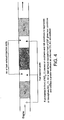
- NO x (1) in the Figures is the first NO x absorbent
- NO x (2) is the second NO x absorbent
- CSF is an acronym for catalysed soot filter.
- a light-duty Diesel engine with a rich in-cylinder calibration was fitted with an exhaust system comprising the arrangement shown in Figure 1, except in that engine management was used to provide engine-derived hydrocarbon enrichment of the exhaust gas, i.e. no fuel was injected downstream of the exhaust manifold, and an air injector was disposed between the NO x trap (1) and a catalysed soot filter.
- the catalysed soot filter was a cordierite wall-flow filter catalysed with a washcoat comprising platinum supported on both an alumina-based particulate refractory oxide and by the filter material itelf.
- the filter was prepared by coating the uncoated filter with a washcoat comprising the refractory oxide, drying and calcining the resulting piece and then impregnating the washcoated filter using an aqueous solution of a platinum salt to a loading of 100 gft -3 (3.53 gl -1 ).
- NO x trap (1) was a low temperature trap comprising a ceramic flow-through monolith substrate coated with a washcoat comprising an alumina-based particulate refractory oxide and an OSC supporting platinum, barium, cerium and rhodium.
- the high temperature NO x trap (2) had a similar construction except in that the formulation included caesium.
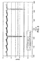
- Figure 6 shows speciation of NO x slip after NO x trap (1).
- NO 2 concentration upstream of the NO x trap is 14 ppm (6% of total NO x ). It can be seen that a high proportion of the NO x is NO 2 (up to 30% of total NO x slip), which is available therefore to react with soot in the downstream CSF according to the process disclosed in EP 0341832.
- the system was configured to cycle between lean and rich running conditions at an engine-out exhaust temperature of 450°C. Lean periods were adjusted to 300s long, each rich period was 8s long. It can be seen from Figure 7 that introducing a rich pulse over NO x trap (1) by reducing the oxygen concentration in the exhaust gas upstream of NO x trap (1) results in a temperature increase of the exhaust gas as reductant is combusted in the remaining oxygen. This extra heat can be used to regenerate NO x trap (1) for NO x or SO x under the rich condition.
- NO x trap (I) Extra fuel was introduced into the exhaust gas upstream of NO x trap (I), but only enough to maintain a lean composition overall. This creates an exotherm that can be used to regenerate the soot in the CSF (see Figure 10). NO x can also be thennal1y released from NO x trap (1) in the same way, resulting in an increase in NO 2 concentration upstream of the CSF, which is available for reaction with soot on the CSF according to the process described in EP 0341832.
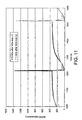
- NO x trap (2) can store NO x that slips from NO x trap (1) and the CSF (see Figure 11) in both the lean and (when air injection is present in between NO x trap (1) and the CSF) during the rich pulse. Regeneration of NO x trap (2) could be readily accomplished with fuel injection in between the CSF and NO x trap (2) as per normal NO x trap operation (see EP 0758713).
Landscapes
- Engineering & Computer Science (AREA)
- Chemical & Material Sciences (AREA)
- Combustion & Propulsion (AREA)
- Chemical Kinetics & Catalysis (AREA)
- Mechanical Engineering (AREA)
- General Engineering & Computer Science (AREA)
- Materials Engineering (AREA)
- Organic Chemistry (AREA)
- Biomedical Technology (AREA)
- Environmental & Geological Engineering (AREA)
- Analytical Chemistry (AREA)
- General Chemical & Material Sciences (AREA)
- Oil, Petroleum & Natural Gas (AREA)
- Health & Medical Sciences (AREA)
- Exhaust Gas After Treatment (AREA)
- Processes For Solid Components From Exhaust (AREA)
- Filtering Of Dispersed Particles In Gases (AREA)
- Catalysts (AREA)
Applications Claiming Priority (3)
| Application Number | Priority Date | Filing Date | Title |
|---|---|---|---|
| GB0305415 | 2003-03-08 | ||
| GBGB0305415.2A GB0305415D0 (en) | 2003-03-08 | 2003-03-08 | Exhaust system for lean burn IC engine including particulate filter and NOx absorbent |
| PCT/GB2004/000994 WO2004079170A1 (en) | 2003-03-08 | 2004-03-08 | EXHAUST SYSTEM FOR LEAN BURN IC ENGINE INCLUDING PARTICULATE FILTER AND NOx ABSORBENT |
Publications (2)
| Publication Number | Publication Date |
|---|---|
| EP1606498A1 EP1606498A1 (en) | 2005-12-21 |
| EP1606498B1 true EP1606498B1 (en) | 2006-11-22 |
Family
ID=9954456
Family Applications (1)
| Application Number | Title | Priority Date | Filing Date |
|---|---|---|---|
| EP04718332A Expired - Lifetime EP1606498B1 (en) | 2003-03-08 | 2004-03-08 | Exhaust system for lean burn ic engine including particulate filter and no sb x /sb absorbent |
Country Status (8)
| Country | Link |
|---|---|
| US (2) | US7930881B2 (enExample) |
| EP (1) | EP1606498B1 (enExample) |
| JP (1) | JP4503593B2 (enExample) |
| KR (1) | KR101110648B1 (enExample) |
| CN (1) | CN100497894C (enExample) |
| DE (1) | DE602004003354T2 (enExample) |
| GB (1) | GB0305415D0 (enExample) |
| WO (1) | WO2004079170A1 (enExample) |
Families Citing this family (51)
| Publication number | Priority date | Publication date | Assignee | Title |
|---|---|---|---|---|
| JP4006645B2 (ja) | 2003-08-27 | 2007-11-14 | トヨタ自動車株式会社 | 排ガス浄化装置 |
| DE10361793A1 (de) * | 2003-12-31 | 2005-07-28 | Volkswagen Ag | NOx-Speicherkatalysator |
| DE10361791A1 (de) * | 2003-12-31 | 2005-07-28 | Volkswagen Ag | Vorrichtung zur Reinigung des Abgases einer Brennkraftmaschine und Verfahren zur Regeneration einer solchen Abgasreinigungsanlage |
| JP2006046200A (ja) * | 2004-08-05 | 2006-02-16 | Hitachi Ltd | ディーゼル内燃機関用排ガス浄化フィルタとその製造方法及び排ガス浄化装置 |
| US7673445B2 (en) * | 2004-11-09 | 2010-03-09 | Ford Global Technologies, Llc | Mechanical apparatus having a catalytic NOx storage and conversion device |
| FR2884872B1 (fr) * | 2005-04-25 | 2007-09-14 | Renault Sas | Procede de commande d'un moteur de vehicule pour reguler la temperature d'un filtre a particules |
| JP2007125524A (ja) * | 2005-11-07 | 2007-05-24 | Toyota Motor Corp | 排ガス浄化装置 |
| JP5010139B2 (ja) * | 2005-11-25 | 2012-08-29 | 三菱重工業株式会社 | 排ガス浄化用触媒およびその製造方法並びに排ガス浄化装置 |
| JP4270201B2 (ja) * | 2005-12-05 | 2009-05-27 | トヨタ自動車株式会社 | 内燃機関 |
| DE102005058858A1 (de) * | 2005-12-09 | 2007-06-14 | Volkswagen Ag | Verfahren zur Abgasnachbehandlung bei Verbrennungsmotoren, und Vorrichtung zur Durchführung dieses Verfahrens |
| JP4523911B2 (ja) * | 2005-12-14 | 2010-08-11 | 本田技研工業株式会社 | 排ガス浄化装置 |
| GB0603898D0 (en) * | 2006-02-28 | 2006-04-05 | Johnson Matthey Plc | Exhaust system comprising catalysed soot filter |
| JP4372764B2 (ja) * | 2006-03-30 | 2009-11-25 | トヨタ自動車株式会社 | 排ガス浄化装置 |
| US8148290B2 (en) * | 2006-06-27 | 2012-04-03 | Basf Corporation | Diesel exhaust treatment system catalyst monitoring |
| GB0620883D0 (en) | 2006-10-20 | 2006-11-29 | Johnson Matthey Plc | Exhaust system for a lean-burn internal combustion engine |
| RU2009132612A (ru) * | 2007-01-31 | 2011-03-10 | Басф Каталистс Ллк (Us) | Газовые катализаторы, включающие пористую сотовидную стенку |
| JP5119690B2 (ja) | 2007-03-12 | 2013-01-16 | トヨタ自動車株式会社 | 内燃機関の排気ガス浄化装置 |
| ATE445769T1 (de) | 2007-03-13 | 2009-10-15 | Yamaha Motor Co Ltd | Abgasreinigungssystem für einen verbrennungsmotor |
| JP4420048B2 (ja) | 2007-03-20 | 2010-02-24 | トヨタ自動車株式会社 | 内燃機関の排気浄化装置 |
| DE102007027677B4 (de) | 2007-06-15 | 2010-12-09 | Süd-Chemie AG | Abgasreinigungssystem |
| US9863297B2 (en) * | 2007-12-12 | 2018-01-09 | Basf Corporation | Emission treatment system |
| US9993771B2 (en) * | 2007-12-12 | 2018-06-12 | Basf Corporation | Emission treatment catalysts, systems and methods |
| EP2093396A1 (en) * | 2008-02-22 | 2009-08-26 | Ford Global Technologies, LLC | An exhaust system and a method for such a system |
| DE102008016177A1 (de) | 2008-03-28 | 2009-10-08 | Süd-Chemie AG | Harnstoffhydrolysekatalysator |
| EP2275203B1 (en) * | 2008-04-14 | 2017-02-01 | Mitsui Mining and Smelting Co., Ltd. | Particulate combustion catalyst, particulate filter and exhaust gas purifying apparatus |
| WO2010053163A1 (ja) | 2008-11-06 | 2010-05-14 | 株式会社 キャタラー | ディーゼル用排ガス浄化触媒及びディーゼル用排ガス浄化システム |
| FR2941264B1 (fr) * | 2009-01-22 | 2011-07-22 | Renault Sas | Systeme de traitement des nox contenus dans des gaz d'echappement. |
| US8555617B2 (en) * | 2009-03-26 | 2013-10-15 | GM Global Technology Operations LLC | Exhaust gas treatment system including a four-way catalyst and urea SCR catalyst and method of using the same |
| US8505279B2 (en) * | 2009-03-26 | 2013-08-13 | GM Global Technology Operations LLC | Exhaust gas treatment system including a four-way catalyst and urea SCR catalyst and method of using the same |
| DE102010033689A1 (de) | 2009-08-28 | 2011-03-03 | Umicore Ag & Co. Kg | Abgasnachbehandlungssystem mit katalytisch aktivem Wall-Flow-Filter mit NOx-Speicherfunktion vor Katalysator mit gleicher Speicherfunktion |
| DE102010033688A1 (de) | 2009-08-28 | 2011-03-03 | Umicore Ag & Co. Kg | Abgasnachbehandlungssystem mit katalytisch aktivem Wall-Flow-Filter mit Speicherfunktion vor Katalysator mit gleicher Speicherfunktion |
| BR112012004378A8 (pt) | 2009-08-28 | 2016-10-04 | Umicore Ag & Co Kg | sistema de pós-tratamento de gás de escapamento com filtro de parede de fluxo cataliticamente ativo com função de armazenamento a montante de conversor catalítico com função de armazenamento idêntica |
| KR101724453B1 (ko) * | 2011-07-13 | 2017-04-10 | 현대자동차 주식회사 | 배기 가스 정화 장치 및 이를 제어하는 방법 |
| CN103732873B (zh) | 2011-07-28 | 2016-03-16 | 丰田自动车株式会社 | 内燃机的排气净化装置 |
| KR101684496B1 (ko) | 2011-09-09 | 2016-12-09 | 현대자동차 주식회사 | 배기가스 정화 장치 및 이를 제어하는 방법 |
| JP6285945B2 (ja) | 2012-11-12 | 2018-02-28 | ユミコア アクチェンゲゼルシャフト ウント コンパニー コマンディートゲゼルシャフト | NOxおよび粒子を含んでいるディーゼル排気ガスを処理するための触媒システム |
| JP2015025433A (ja) | 2013-07-29 | 2015-02-05 | 三菱自動車工業株式会社 | 内燃機関の排気浄化装置 |
| DE102014206455A1 (de) * | 2014-04-03 | 2015-10-08 | Umicore Ag & Co. Kg | Regenerationsverfahren für Abgasnachbehandlungssysteme |
| JP6576461B2 (ja) * | 2015-03-20 | 2019-09-18 | ハルドール・トプサー・アクチエゼルスカベット | 触媒化セラミックキャンドルフィルタ及びプロセスオフガスまたは排ガスの清浄方法 |
| GB2540350A (en) * | 2015-07-09 | 2017-01-18 | Johnson Matthey Plc | Nitrogen oxides (NOx) storage catalyst |
| DE102015219113A1 (de) * | 2015-10-02 | 2017-04-06 | Volkswagen Ag | Verfahren und Vorrichtung zur Abgasnachbehandlung eines Verbrennungsmotors |
| GB201517580D0 (en) * | 2015-10-06 | 2015-11-18 | Johnson Matthey Plc | Exhaust system comprising a passive nox adsorber |
| EP3400103A4 (en) * | 2016-01-06 | 2019-07-31 | BASF Corporation | DIESEL OXIDATION CATALYST WITH PLATINUM GROUND METAL NANOPARTICLES |
| DE102016208289A1 (de) * | 2016-02-29 | 2017-08-31 | Volkswagen Aktiengesellschaft | Brennkraftmaschine mit einem fremdgezündeten Verbrennungsmotor und Verfahren zum Betreiben einer derartigen Brennkraftmaschine |
| US10323594B2 (en) | 2016-06-17 | 2019-06-18 | Ford Global Technologies, Llc | Methods and systems for treating vehicle emissions |
| GB2554859A (en) | 2016-10-04 | 2018-04-18 | Johnson Matthey Plc | NOx adsorber catalyst |
| DE102017201401B4 (de) * | 2017-01-30 | 2018-08-23 | Ford Global Technologies, Llc | Abgasnachbehandlung |
| US10953366B2 (en) | 2018-04-20 | 2021-03-23 | GM Global Technology Operations LLC | Nitrogen oxides and hydrocarbon storage catalyst and methods of using the same |
| US10399037B1 (en) * | 2018-04-20 | 2019-09-03 | GM Global Technology Operations LLC | Nitrogen oxides storage catalyst and methods of using the same |
| DE102018206355B3 (de) | 2018-04-25 | 2019-08-14 | Ford Global Technologies, Llc | Kraftfahrzeug und Betriebsverfahren |
| DE102019101982A1 (de) * | 2019-01-28 | 2020-07-30 | Volkswagen Aktiengesellschaft | Verfahren und Vorrichtung zur Abgastemperaturregulierung eines Verbrennungsmotors |
Family Cites Families (24)
| Publication number | Priority date | Publication date | Assignee | Title |
|---|---|---|---|---|
| US4329162A (en) * | 1980-07-03 | 1982-05-11 | Corning Glass Works | Diesel particulate trap |
| US4902487A (en) | 1988-05-13 | 1990-02-20 | Johnson Matthey, Inc. | Treatment of diesel exhaust gases |
| WO1993007363A1 (en) | 1991-10-03 | 1993-04-15 | Toyota Jidosha Kabushiki Kaisha | Device for purifying exhaust of internal combustion engine |
| JP3899534B2 (ja) | 1995-08-14 | 2007-03-28 | トヨタ自動車株式会社 | ディーゼル機関の排気浄化方法 |
| JP3228232B2 (ja) * | 1998-07-28 | 2001-11-12 | トヨタ自動車株式会社 | 内燃機関の排気浄化装置 |
| DE19842625C2 (de) * | 1998-09-17 | 2003-03-27 | Daimler Chrysler Ag | Verfahren zum Betrieb einer Verbrennungsmotoranlage mit schwefelanreichernder Abgasreinigungskomponente und damit betreibbare Verbrennungsmotoranlage |
| EP1128895B1 (en) * | 1998-10-12 | 2004-04-07 | Johnson Matthey Public Limited Company | Process and apparatus for treating combustion exhaust gas |
| ATE224507T1 (de) * | 1998-12-05 | 2002-10-15 | Johnson Matthey Plc | Verbesserungen bei abgaspartikelkontrolle |
| JP3551805B2 (ja) * | 1999-01-12 | 2004-08-11 | トヨタ自動車株式会社 | 内燃機関の排気浄化装置 |
| DE19921974A1 (de) * | 1999-05-12 | 2000-11-16 | Volkswagen Ag | Vorrichtung zum Reduzieren von schädlichen Bestandteilen im Abgas einer Brennkraftmaschine, insbesondere einer Diesel-Brennkraftmaschine |
| FI107828B (fi) | 1999-05-18 | 2001-10-15 | Kemira Metalkat Oy | Dieselmoottoreiden pakokaasujen puhdistusjärjestelmä ja menetelmä dieselmoottoreiden pakokaasujen puhdistamiseksi |
| US6314722B1 (en) * | 1999-10-06 | 2001-11-13 | Matros Technologies, Inc. | Method and apparatus for emission control |
| JP3733834B2 (ja) * | 2000-05-02 | 2006-01-11 | 日産自動車株式会社 | 内燃機関の排気浄化装置 |
| DE10023439A1 (de) * | 2000-05-12 | 2001-11-22 | Dmc2 Degussa Metals Catalysts | Verfahren zur Entfernung von Stickoxiden und Rußpartikeln aus dem mageren Abgas eines Verbrennungsmotors und Abgasreinigungssystem hierfür |
| JP3558055B2 (ja) * | 2000-06-29 | 2004-08-25 | トヨタ自動車株式会社 | 内燃機関の排気浄化装置 |
| DE10040554B4 (de) * | 2000-08-15 | 2013-05-02 | Daimler Ag | Verfahren zum Betrieb einer Abgasreinigungsanlage mit Partikelfilter und Stickoxidspeicher |
| US6729125B2 (en) * | 2000-09-19 | 2004-05-04 | Nissan Motor Co., Ltd. | Exhaust gas purifying system |
| US6758036B1 (en) * | 2000-10-27 | 2004-07-06 | Delphi Technologies, Inc. | Method for sulfur protection of NOx adsorber |
| JP2002188432A (ja) * | 2000-12-19 | 2002-07-05 | Isuzu Motors Ltd | ディーゼルエンジンの排気浄化装置 |
| JP4604374B2 (ja) * | 2001-03-15 | 2011-01-05 | 日産自動車株式会社 | 内燃機関の排気浄化装置 |
| JP2003013732A (ja) * | 2001-07-02 | 2003-01-15 | Toyota Motor Corp | 内燃機関の排気浄化装置 |
| DE10151425A1 (de) * | 2001-10-18 | 2003-04-30 | Opel Adam Ag | Partikelfilter zum Reinigen von motorischen Abgasen |
| DE10162383A1 (de) * | 2001-12-19 | 2003-07-17 | Bosch Gmbh Robert | Anordnung und Verfahren zur Nachbehandlung von Abgasen |
| US6938412B2 (en) * | 2003-08-07 | 2005-09-06 | General Motors Corporation | Removing nitrogen oxides during a lean-burn engine cold start |
-
2003
- 2003-03-08 GB GBGB0305415.2A patent/GB0305415D0/en not_active Ceased
-
2004
- 2004-03-08 US US10/547,916 patent/US7930881B2/en not_active Expired - Fee Related
- 2004-03-08 WO PCT/GB2004/000994 patent/WO2004079170A1/en not_active Ceased
- 2004-03-08 JP JP2006505932A patent/JP4503593B2/ja not_active Expired - Fee Related
- 2004-03-08 DE DE602004003354T patent/DE602004003354T2/de not_active Expired - Lifetime
- 2004-03-08 CN CNB2004800121227A patent/CN100497894C/zh not_active Expired - Fee Related
- 2004-03-08 EP EP04718332A patent/EP1606498B1/en not_active Expired - Lifetime
-
2005
- 2005-09-08 KR KR1020057016747A patent/KR101110648B1/ko not_active Expired - Fee Related
-
2011
- 2011-04-25 US US13/093,497 patent/US8752367B2/en not_active Expired - Fee Related
Also Published As
| Publication number | Publication date |
|---|---|
| CN1784540A (zh) | 2006-06-07 |
| CN100497894C (zh) | 2009-06-10 |
| EP1606498A1 (en) | 2005-12-21 |
| JP2006522272A (ja) | 2006-09-28 |
| US20110258993A1 (en) | 2011-10-27 |
| WO2004079170A1 (en) | 2004-09-16 |
| US20060248874A1 (en) | 2006-11-09 |
| KR20050115274A (ko) | 2005-12-07 |
| KR101110648B1 (ko) | 2012-03-02 |
| GB0305415D0 (en) | 2003-04-16 |
| US7930881B2 (en) | 2011-04-26 |
| US8752367B2 (en) | 2014-06-17 |
| DE602004003354D1 (de) | 2007-01-04 |
| DE602004003354T2 (de) | 2007-10-04 |
| JP4503593B2 (ja) | 2010-07-14 |
Similar Documents
| Publication | Publication Date | Title |
|---|---|---|
| EP1606498B1 (en) | Exhaust system for lean burn ic engine including particulate filter and no sb x /sb absorbent | |
| KR101060125B1 (ko) | 희박 연소 ic 엔진용 배기 시스템 | |
| US8006485B2 (en) | Compression ignition engine and exhaust system therefor | |
| US9527031B2 (en) | Exhaust system for a lean burn IC engine | |
| RU2597090C2 (ru) | Каталитический фильтр с двойной функцией | |
| US20180080359A1 (en) | Scr diesel particle filter with oxidation catalyst and oxygen storage catalyst loadings, and exhaust system including the same | |
| JP2004036609A (ja) | 再生段階中に堆積スス粒子の焼却を加速する触媒活性コーティングを有する粒子フィルター | |
| WO2000035564A1 (en) | Exhaust emission control system for internal combustion engines, exhaust emission control method and exhaust emission control catalyst | |
| CN101001688A (zh) | 催化还原氮氧化物的方法 | |
| EP1370343B1 (en) | GAS TREATMENT USING NOx-SPECIFIC REACTANT | |
| KR100902272B1 (ko) | 내연 기관용 배기 라인 | |
| US20080261801A1 (en) | Methods of Regenerating a Nox Absorbent | |
| HK1092514A (en) | Exhaust system for lean burn ic engine including particulate filter and nox absorbent | |
| JP2010249142A (ja) | 燃焼排気ガスを処理する方法および装置 | |
| HK1064978B (en) | Gas treatment using nox-specific reactant |
Legal Events
| Date | Code | Title | Description |
|---|---|---|---|
| PUAI | Public reference made under article 153(3) epc to a published international application that has entered the european phase |
Free format text: ORIGINAL CODE: 0009012 |
|
| 17P | Request for examination filed |
Effective date: 20050906 |
|
| AK | Designated contracting states |
Kind code of ref document: A1 Designated state(s): AT BE BG CH CY CZ DE DK EE ES FI FR GB GR HU IE IT LI LU MC NL PL PT RO SE SI SK TR |
|
| AX | Request for extension of the european patent |
Extension state: AL LT LV MK |
|
| RIN1 | Information on inventor provided before grant (corrected) |
Inventor name: GOERSMANN, CLAUS, FRIEDRICH Inventor name: CHANDLER, GUY RICHARD Inventor name: PHILLIPS, PAUL, RICHARD Inventor name: BLAKEMAN, PHILIP GERALD |
|
| GRAP | Despatch of communication of intention to grant a patent |
Free format text: ORIGINAL CODE: EPIDOSNIGR1 |
|
| DAX | Request for extension of the european patent (deleted) | ||
| RBV | Designated contracting states (corrected) |
Designated state(s): DE FR GB GR IT SE |
|
| GRAS | Grant fee paid |
Free format text: ORIGINAL CODE: EPIDOSNIGR3 |
|
| GRAA | (expected) grant |
Free format text: ORIGINAL CODE: 0009210 |
|
| AK | Designated contracting states |
Kind code of ref document: B1 Designated state(s): DE FR GB GR IT SE |
|
| REG | Reference to a national code |
Ref country code: GB Ref legal event code: FG4D |
|
| REG | Reference to a national code |
Ref country code: GR Ref legal event code: EP Ref document number: 20060404062 Country of ref document: GR |
|
| REF | Corresponds to: |
Ref document number: 602004003354 Country of ref document: DE Date of ref document: 20070104 Kind code of ref document: P |
|
| REG | Reference to a national code |
Ref country code: SE Ref legal event code: TRGR |
|
| ET | Fr: translation filed | ||
| PLBE | No opposition filed within time limit |
Free format text: ORIGINAL CODE: 0009261 |
|
| STAA | Information on the status of an ep patent application or granted ep patent |
Free format text: STATUS: NO OPPOSITION FILED WITHIN TIME LIMIT |
|
| 26N | No opposition filed |
Effective date: 20070823 |
|
| PGFP | Annual fee paid to national office [announced via postgrant information from national office to epo] |
Ref country code: IT Payment date: 20080219 Year of fee payment: 5 Ref country code: SE Payment date: 20080218 Year of fee payment: 5 |
|
| PGFP | Annual fee paid to national office [announced via postgrant information from national office to epo] |
Ref country code: FR Payment date: 20080211 Year of fee payment: 5 |
|
| PGFP | Annual fee paid to national office [announced via postgrant information from national office to epo] |
Ref country code: GR Payment date: 20080227 Year of fee payment: 5 |
|
| EUG | Se: european patent has lapsed | ||
| REG | Reference to a national code |
Ref country code: FR Ref legal event code: ST Effective date: 20091130 |
|
| PG25 | Lapsed in a contracting state [announced via postgrant information from national office to epo] |
Ref country code: FR Free format text: LAPSE BECAUSE OF NON-PAYMENT OF DUE FEES Effective date: 20091123 |
|
| PG25 | Lapsed in a contracting state [announced via postgrant information from national office to epo] |
Ref country code: GR Free format text: LAPSE BECAUSE OF NON-PAYMENT OF DUE FEES Effective date: 20091002 |
|
| PG25 | Lapsed in a contracting state [announced via postgrant information from national office to epo] |
Ref country code: IT Free format text: LAPSE BECAUSE OF NON-PAYMENT OF DUE FEES Effective date: 20090308 |
|
| PG25 | Lapsed in a contracting state [announced via postgrant information from national office to epo] |
Ref country code: SE Free format text: LAPSE BECAUSE OF NON-PAYMENT OF DUE FEES Effective date: 20090309 |
|
| REG | Reference to a national code |
Ref country code: DE Ref legal event code: R082 Ref document number: 602004003354 Country of ref document: DE Representative=s name: BARDEHLE PAGENBERG PARTNERSCHAFT MBB PATENTANW, DE |
|
| PGFP | Annual fee paid to national office [announced via postgrant information from national office to epo] |
Ref country code: GB Payment date: 20230222 Year of fee payment: 20 Ref country code: DE Payment date: 20230221 Year of fee payment: 20 |
|
| P01 | Opt-out of the competence of the unified patent court (upc) registered |
Effective date: 20230526 |
|
| REG | Reference to a national code |
Ref country code: DE Ref legal event code: R071 Ref document number: 602004003354 Country of ref document: DE |
|
| REG | Reference to a national code |
Ref country code: GB Ref legal event code: PE20 Expiry date: 20240307 |
|
| PG25 | Lapsed in a contracting state [announced via postgrant information from national office to epo] |
Ref country code: GB Free format text: LAPSE BECAUSE OF EXPIRATION OF PROTECTION Effective date: 20240307 |