EP1605555A1 - Elektrischer Steckverbinder - Google Patents
Elektrischer Steckverbinder Download PDFInfo
- Publication number
- EP1605555A1 EP1605555A1 EP04013396A EP04013396A EP1605555A1 EP 1605555 A1 EP1605555 A1 EP 1605555A1 EP 04013396 A EP04013396 A EP 04013396A EP 04013396 A EP04013396 A EP 04013396A EP 1605555 A1 EP1605555 A1 EP 1605555A1
- Authority
- EP
- European Patent Office
- Prior art keywords
- connector
- securing
- connector according
- securing element
- movable
- Prior art date
- Legal status (The legal status is an assumption and is not a legal conclusion. Google has not performed a legal analysis and makes no representation as to the accuracy of the status listed.)
- Granted
Links
- 210000002105 tongue Anatomy 0.000 claims description 38
- 238000003780 insertion Methods 0.000 claims description 12
- 230000037431 insertion Effects 0.000 claims description 12
- 230000013011 mating Effects 0.000 claims description 11
- 238000006073 displacement reaction Methods 0.000 claims description 2
- 238000005452 bending Methods 0.000 description 4
- 229910000859 α-Fe Inorganic materials 0.000 description 4
- 230000032258 transport Effects 0.000 description 3
- 230000009849 deactivation Effects 0.000 description 2
- 238000001746 injection moulding Methods 0.000 description 1
- 238000002360 preparation method Methods 0.000 description 1
Images






Classifications
-
- H—ELECTRICITY
- H01—ELECTRIC ELEMENTS
- H01R—ELECTRICALLY-CONDUCTIVE CONNECTIONS; STRUCTURAL ASSOCIATIONS OF A PLURALITY OF MUTUALLY-INSULATED ELECTRICAL CONNECTING ELEMENTS; COUPLING DEVICES; CURRENT COLLECTORS
- H01R13/00—Details of coupling devices of the kinds covered by groups H01R12/70 or H01R24/00 - H01R33/00
- H01R13/62—Means for facilitating engagement or disengagement of coupling parts or for holding them in engagement
- H01R13/639—Additional means for holding or locking coupling parts together, after engagement, e.g. separate keylock, retainer strap
-
- H—ELECTRICITY
- H01—ELECTRIC ELEMENTS
- H01R—ELECTRICALLY-CONDUCTIVE CONNECTIONS; STRUCTURAL ASSOCIATIONS OF A PLURALITY OF MUTUALLY-INSULATED ELECTRICAL CONNECTING ELEMENTS; COUPLING DEVICES; CURRENT COLLECTORS
- H01R13/00—Details of coupling devices of the kinds covered by groups H01R12/70 or H01R24/00 - H01R33/00
- H01R13/66—Structural association with built-in electrical component
- H01R13/70—Structural association with built-in electrical component with built-in switch
- H01R13/701—Structural association with built-in electrical component with built-in switch the switch being actuated by an accessory, e.g. cover, locking member
Definitions
- the invention relates to a connector with two mating, latchable connector parts, a fuse element, movably mounted on one of the two connector parts and in a Fuse position is movable, in particular it is the locking connection secures between the two connector parts, and one the other Connector part associated shorting bridge, on the at least two Contacts of the other connector part electrically connected to each other are.
- the securing element may be a act as a CPA (Connector Position Assurance) element.
- the invention has the object, a connector of the type mentioned above, in which the shorting bridge also in one of the actuating direction of the securing element deviating opening or operating direction easily deactivated is.
- tongue By sliding along a curved path tongue is the Actuation direction deflected accordingly.
- the opening or actuating direction The short-circuiting bridge can therefore be of the operating direction differ from the fuse element.
- This can be the curved Path along which the tongue is displaceable, for example partially circular be: By a correspondingly large radius of the curved Track can be made sure that the tongue is as smooth as possible is displaceable.
- a preferred practical embodiment of the invention Connector is characterized in that the result of the curved Orbit caused change in the direction of actuation is about 90 °, i.e. that of the shorting bridge facing and engaged with this bringable end of the sliding along the curved path tongue is moved in one direction, that of the direction of movement of the fuse element deviates by about 90 °.
- the securing element can, for example, perpendicular to the direction of insertion, in which the two connector parts are plugged together, be movable.
- Tongue preferably movable in the insertion direction.
- the shorting bridge is preferred with a respective overpass the securing element in its securing position and a corresponding Move the tongue open along the curved path.
- the tongue is curved along the Rail moved back again. In this case, the tongue, for example by the security element moved out of its securing position get picked up.
- the fuse element is fully mated Connector parts movable in its securing position.
- At least two are connected to each other via a web connected tongues provided.
- the tongues for example, can each interact with a contact.
- the securing element can be designed in particular as a slide, which is guided displaceably on the relevant connector part.
- Connector is the fuse element at one with the Housing of the relevant connector part latchable locking plate slidably guided.
- the fuse element in particular displaceable by a ring clamping connection on this backup plate be held.
- the securing plate is preferably divided into two sections by a hinge, in particular a film hinge, in order to form a type of flap which, in the closed state, holds and secures contacts brought into the relevant connector part in the desired position.
- the connector part provided with the securing element is advantageously provided with a release element, which is movable with the mating of the two connector parts in a release position in which the securing element is released for transfer to its securing position.
- this release element with respect to the relevant Connector parts in the insertion direction, in which the two connector parts can be plugged together are, movable.
- the locking connection between the two connector parts is advantageously by moving out of the fuse element from its securing position solvable.
- At least one of the two Connector parts is provided with at least one resilient latching arm, the extends generally in the direction of insertion and with a respective, on other connector part provided counter-locking means cooperates. It can, for example, on two opposite sides in each case at least one latching arm can be provided.
- Connector is the resilient latching arm when mating the Both connector parts against the spring force inwardly deflectable, wherein he then to produce the locking connection to the outside snaps back.
- the resilient latching arm is by its securing position engaging securing element prevented from being deflected inwards to become.
- the securing element for example, with a locking bolt provided and the resilient latching arm in its securing position einskydem Fuse element prevented by this locking bar to be deflected inward.
- the securing element expediently movable into a release position, in which the locking bolt with a recess of the resilient latching arm is aligned so that this against the spring force inward is deflectable:
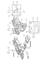
- Figures 1 to 31 show an embodiment of a connector 10, which is for example an electrical connector can act.
- the shorting bridge 18 is over two, for example, through the Locking element 16 acted upon elastic, along a curved Track displaceable tongues operable (see in particular the Figures 8, 9, 12, 19, 28 and 29).
- the two tongues are connected to one another via a web 24 connected.
- the shorting bridge 18 facing and engageable with this ends 26 of the displaceable along the curved path tongues 22 are thus movable in a direction II, which differs from the direction of movement 1 of the securing element 16 by about 90 °.
- the opening or actuating direction II of the short-circuiting bridge 18 forms an angle of approximately 90 ° with the actuating or movement direction I of the securing element 16 (cf., in particular, FIGS. 28 and 29).
- the securing element 16 is movable perpendicular to the insertion direction S (cf., in particular, FIGS. 1 and 24 to 31), in which the two connector parts 12, 14 can be joined together.
- the securing element 16 at fully mated connector parts 12, 14 in its safety position movable.
- the fuse element 16 is designed as a slide, the first Connector part 12 is slidably guided. In the present case this is Securing element 16 at one with the housing 28 of the first connector part 12 latchable locking plate 30 slidably guided.
- the securing element 16 may be provided by a ring clamping connection 32 (see in particular Figures 10 and 11) slidably on the Backup plate 30 be held.
- the connector 10 may be at least partially made of plastic.
- the locking plate 30 is by a hinge 34, which in particular to act as a film hinge, in two sections 30 ', 30 " divided. In this case, a kind of flap is formed, which in the closed Condition in the first connector part 12 introduced contacts 36 in the holds the desired position and secures (see in particular Figures 3, 18 and 19).
- the connector element 12 provided with the securing element 16 can Moreover, be provided with a release element 38, which with the mating the two connector parts 12, 14 in a release position is movable (see in particular Figure 26), in which the securing element 16 is freed for transfer into its securing position. As can be seen in particular with reference to Figures 26 and 27, this is Release element 38 with respect to the first connector part 12 in the insertion direction S movable.
- the latching connection between the two connector parts 12, 14 is through Moving out of the fuse element 16 from its securing position solvable.
- the resilient latching arms 40 for example, with a respective Projection 44 be provided, the fully mated Connector parts 12, 14 then engages in the respective groove 42.
- the two are on opposite sides Side arranged resilient latching arms 40 when mating the Connector parts 12, 14 against the spring force, for example, inwards deflectable to subsequently for the preparation of the locking connection after Snap back outside.
- the securing element is 16 provided with two locking bolts 46, through which the resilient Latching arms 40 in its securing position einskydem fuse element 16 are prevented from being deflected inward.
- the securing element 16 For releasing the latching connection between the two connector parts 12, 14 is the securing element 16 in a release position or its starting position movable, in which the locking bolt 46 each with a recess 48 of the resilient latching arms 40 are aligned so that this against the spring force are deflected inwards.
- the elastic tongues 22 thus ensure that the opening or actuation direction of the short-circuiting bridge 18, for example about 90 ° relative to the actuation direction of the securing element 16 differs.
- By deflecting the actuating direction over a relative large radius is a relatively smooth leadership of the tongues 22nd ensured along the curved curve.
- Figure 1 shows the assembled connector 10, the two connector parts 12, 14 are completely plugged together.
- the with the first connector part 12 connected lines are labeled "50". These lines 50 are provided with contacts or terminals.
- ferrite cores 52 may be used.
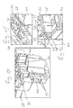
- FIG. 3 shows the assembled first connector part 12 in a state in which it is delivered to the cable harness.
- the housing 28 of the first connector part 12 is in the state reproduced by falling out of the tool.
- the connector can be made of plastic, so this Housing 28 can be produced in particular by injection molding.
- the locking arms 40 were folded down as shown, leaving only a jaw / slider must be used.
- the jaw creates the groove and Spring in the lower part of the locking arms and gives the undercut on Locking hooks of the locking arms free.
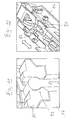
- the tongues 22 When mounting the tongues 22 in the housing 28, the tongues must 22nd or the web 24 through a rectangular opening 60 of the housing 28th be plugged. It is through the tongues 22 and the web 24 a pressed on the housing 28 provided latch hook 62 down. Become moves the tongues 22 back to the position shown in FIG. 9, Thus, the latching hook 62 relaxes again and thus ensures the correct position of the tongues 22.
- the fuse element 16 for example displaceable by a ring clamping connection 32 at the Backup plate 30 be held.
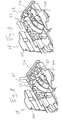
- Figure 14 shows a schematic partial view of the housing 28 with inserted Ferrite cores 52, by the latched locking plate 30 in position being held.
- Figure 17 shows a schematic partial view of the housing 28 with inserted Lines 50 with associated contacts or terminals and a Strain relief for the terminals.
- the strain relief includes the housing 28 associated ribs 70.
- five such ribs 70 are provided, each having a respective Clamp in line 50 in the first connector part 12.
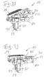
- FIGS. 22 and 23 show the exact positioning of the securing element 16 during the closing of the backup plate 30th
- FIG. 22 shows the first connector part 12 in a state in which the flap formed by the locking plate 30 is still open, the Securing element 16, for example, as a result of improper transport but already occupies its security position. While closing the locking plate 30 abut rear locking hooks 78 of the securing element 16 against locking hook 80 on the housing 28, whereby the securing element 16 is pushed forward. With the flap closed, this is Fuse 16 thus brought into its correct starting position and positioned by snap hooks (see Figure 23). In addition, that will Securing element 16 by the release element 38 in this position held.
- FIG. 24 shows a schematic, partially broken-away partial view the connector 10 when mating the two connector parts 12, 14.
- the second connector part 14 for example, a squib or the like.
- FIG. 25 also shows a schematic, partially broken-away partial view the connector 10 in a state in which the two Connector parts 12, 14 are already plugged together so far that the Release element 38 on a second connector part 14 and the Squib associated with holder or retainer 82 rests.
- the fuse element 16 is here by the release element 38 but how from being prevented from its end position to the securing position to be moved.
- the resilient latching arms 40 are inside pressed.
- FIG. 26 shows a schematic, partially broken-away partial view the connector 10 in a state in which the two connector parts 12, 14 are completely plugged together and the release element 38th is pushed up, the fuse element 16 is still his Starting position occupies. After the release element 38 upward is pressed, the fuse element 16 is now, however, for a Transfer to the safety position released.
- the build Bending beam 38 'of the release element 38 to a voltage.
- FIG. 27 shows a representation comparable to FIG. 26, wherein FIG However, fuse element 16 already moved into its securing position is. The fuse element 16 has thus been moved to the rear, while the bending beam 38 'of the release element 38 again free of tension are.
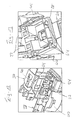
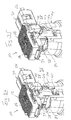
- Figure 28 shows a schematic sectional view of the connector 10 in a state in which the two connector parts 12, 14 already are completely mated, the shorting bridge 18, however still active, i. is closed or on the pin-like contacts 20th is applied.
- FIG. 29 shows a representation comparable to FIG. 28, wherein FIG However fuse element 16 is moved to its securing position and the Shorting bridge 18 is deactivated or opened by the tongues 22, i. is lifted from the pin-like contacts 20.
- the tongues were 22 So for deactivation of the shorting bridge 18 according to moved down.
- Figure 30 shows the connector 10 in a state in which the two Connector parts 12, 14 are already completely plugged together, the However, fuse element 12 still assumes its initial position, so that the resilient latching arms 40 are deflected inwards.
- FIG. 31 shows a representation comparable to FIG. 30, wherein FIG However, fuse element 16 is moved to its securing position and the locking arms 40 by the securing element 16 provided on the locking bolt 46 are prevented from being deflected inward. The two assembled connector parts 12, 14 are now through secured the fuse element 16.
- the fuse element 16 For releasing the latching connection between the two connector parts 12, 14, the fuse element 16 is shown in its FIG. 31 Backup position back to its starting position shown in Figure 30 pushed back, whereby the resilient latching arms 40 released and the shorting bridge 18 is activated again. Will the resilient latching arms 40 now pressed inward, so the projections dissolve 44 from the grooves 42. The two connector parts 12, 14 can then be pulled apart again. The release element drops 38 down again.
- the housing 28 of the first connector part 12 may below two Wülste be attached, which ensure that the securing tongues 22 in the final position even further stand out from the case and thus the shorting bridge 18 also continues to lift.
- cam-like hold-downs acting on the terminals can 72 are increased on the backup plate 30.
- the release element 38 and the securing element can, for example also be made as a part.
- the fuse element 16 is in the present case, for example, plate-like executed, i. provided in the form of a security or CPA plate.
Landscapes
- Details Of Connecting Devices For Male And Female Coupling (AREA)
Abstract
Description
Das mit dem Sicherungselement versehene Verbinderteil ist vorteilhafterweise mit einem Freigabeelement versehen, das mit dem Zusammenstecken der beiden Verbinderteile in eine Freigabeposition bewegbar ist, in der das Sicherungselement für eine Überführung in dessen Sicherungsstellung freigegeben ist.
- Figur 1
- eine schematische Darstellung eines Steckverbinders, dessen beide Verbinderteile vollständig zusammengesteckt sind,
- Figur 2
- eine schematische auseinandergezogene Darstellung des mit dem Sicherungselement versehenen ersten Verbinderteils,
- Figur 3
- eine schematische perspektivische Darstellung des ersten Verbinderteils in dem Zustand, in dem es an das Kabelsatzwerk angeliefert wird,
- Figur 4
- eine schematische perspektivische Darstellung des Gehäuses des ersten Verbinderteils in dem Zustand, in dem es aus dem Werkzeug fällt,
- Figur 5
- das Gehäuse gemäß Figur 4 mit beigeklappten Rastarmen,
- Figur 6
- eine vergrößerte Darstellung eines Teils der Figur 5,
- Figur 7
- eine vergrößerte Darstellung eines Teils der Figur 5,
- Figur 8
- eine schematische Teilansicht des Gehäuses des ersten Verbinderteils mit eingesetzten Zungen, wobei durch die Zungen ein am Gehäuse vorgesehener Rasthaken nach unten gedrückt wird,
- Figur 9
- eine mit der Figur 8 vergleichbare Darstellung, wobei die Zungen jedoch nach hinten bewegt wurden und der wieder entspannte Rasthaken die korrekte Position der Zungen gewährleistet,
- Figur 10
- eine schematische Teilansicht des durch eine Ringspannverbindung verschiebbar an der Sicherungsplatte gehaltenen Sicherungselements,
- Figur 11
- eine vergrößerte Darstellung der Ringspannverbindung zwischen der Sicherungsplatte und dem Sicherungselement,
- Figur 12
- eine schematische Teilansicht des Gehäuses des ersten Verbinderteils und der Sicherungsplatte beim Verrasten der Sicherungsplatte mit dem Gehäuse,
- Figur 13
- eine schematische Teilansicht des Gehäuses gemäß Figur 12 von unten,
- Figur 14
- eine schematische Teilansicht des Gehäuses mit eingesetzten Ferritkernen, die durch die verrastete Sicherungsplatte in Position gehalten werden,
- Figur 15
- eine schematische Teilansicht des Gehäuses mit eingesetztem Freigabeelement, das beweglich im Gehäuse gelagert und über Rasthaken unverlierbar an diesen angeordnet ist,
- Figur 16
- eine schematische Teilansicht des Gehäuses gemäß Figur 15 von unten,
- Figur 17
- eine schematische Teilansicht des Gehäuses mit eingesetzten Kontakten und einer Zugentlastung für dessen Terminals,
- Figur 18
- eine schematische perspektivische Darstellung des ersten Verbinderteils vor dem Schließen der durch die Sicherungsplatte gebildeten Klappe,
- Figur 19
- eine vergrößerte geschnittene Teildarstellung eines Kontaktbereichs des ersten Verbinderteils nach dem Schließen der Klappe,
- Figur 20
- eine schematische Teildarstellung des das Freigabeelement aufnehmenden Endes des ersten Verbinderteils von unten,
- Figur 21
- eine schematische Teildarstellung des die Leitungen aufnehmenden Endes des ersten Verbinderteils,
- Figur 22
- eine schematische Darstellung des ersten Verbinderteils in einen Zustand, in dem die Klappe noch geöffnet ist, das Sicherungselement beispielsweise infolge eines unsachgemäßen Transportes jedoch bereits seine Sicherungsstellung einnimmt,
- Figur 23
- eine schematische Darstellung des ersten Verbinderteils in einem Zustand, in dem die Klappe geschlossen und das Sicherungselement in die korrekte Ausgangsstellung gebracht ist, in der es durch Rastnocken gehalten ist,
- Figur 24
- eine schematische, teilweise aufgebrochene Teildarstellung des Steckverbinders beim Zusammenstecken der beiden Verbinderteile,
- Figur 25
- eine schematische, teilweise aufgebrochene Teildarstellung des Steckverbinders in einem Zustand, in dem die beiden Verbinderteile bereits soweit zusammengesteckt sind, dass das Freigabeelement auf einer dem zweiten Verbinderteil zugeordneten Halterung aufliegt,
- Figur 26
- eine schematische teilweise aufgebrochene Teildarstellung des Steckverbinders in einem Zustand, in dem die beiden Verbinderteile vollständig zusammengesteckt sind und das Freigabeelement nach oben gedrückt ist, wobei das Sicherungselement noch seine Ausgangsstellung einnimmt,
- Figur 27
- eine mit der Figur 26 vergleichbare Darstellung, wobei das Sicherungselement jedoch bereits in seine Sicherungsstellung bewegt ist,
- Figur 28
- eine schematische geschnittene Darstellung des Steckverbinders in einen Zustand, in dem die beiden Verbinderteile bereits vollständig zusammengesteckt sind, die Kurzschlussbrücke jedoch noch aktiv ist,
- Figur 29
- eine mit der Figur 28 vergleichbare Darstellung, wobei das Sicherungselement jedoch in seine Sicherungsstellung bewegt und die Kurzschlussbrücke durch die Zungen geöffnet bzw. von den Stiften abgehoben ist,
- Figur 30
- eine schematische Darstellung des Steckverbinders in einem Zustand, in dem die beiden Verbinderteile bereits vollständig zusammengesteckt sind, das Sicherungselement jedoch noch seine Ausgangsstellung einnimmt, so dass die federnden Rastarme nach innen auslenkbar sind, und
- Figur 31
- eine mit der Figur 30 vergleichbare Darstellung, wobei das Sicherungselement jedoch in seine Sicherungsstellung bewegt ist und die Rastarme durch am Sicherungselement vorgesehene Sperrriegel daran gehindert sind, nach innen ausgelenkt zu werden.
Das Sicherungselement 16 ist senkrecht zur Steckrichtung S (vgl. insbesondere die Figuren 1 und 24 bis 31), in der die beiden Verbinderteile 12, 14 zusammensteckbar sind, bewegbar.
- 10
- Steckverbinder
- 12
- erstes Verbinderteil
- 14
- zweites Verbinderteil
- 16
- Sicherungselement
- 18
- Kurzschlussbrücke
- 20
- Kontakte
- 22
- Zungen
- 24
- Steg
- 26
- Ende
- 28
- Gehäuse
- 30
- Sicherungsplatte
- 30'
- Abschnitt
- 30"
- Abschnitt
- 32
- Ringspannverbindung
- 34
- Gelenk, Filmscharnier
- 36
- Kontakt
- 38
- Freigabeelement
- 38'
- Biegebalken
- 40
- federnder Rastarm
- 42
- Gegenrastmittel, Nut
- 44
- Vorsprung
- 46
- Sperrriegel
- 48
- Ausnehmung
- 50
- Leitung
- 52
- Ferritkern
- 54
- Nut
- 56
- Filmscharnier
- 58
- Sicherungshaken
- 60
- Öffnung
- 62
- Rasthaken
- 64
- Rasthaken
- 66
- Rastarm
- 68
- Nut
- 70
- Rippe
- 72
- Niederhalter
- 74
- Rasthaken
- 76
- Zentrierdorn
- 78
- Rasthaken
- 80
- Rasthaken
- 82
- Halterung, Retainer
- S
- Steckrichtung
- I
- Betätigungsrichtung des Sicherungselements
- II
- Öffnungs- oder Betätigungsrichtung der Kurzschlussbrücke
Claims (20)
- Steckverbinder (10) mit zwei zusammensteckbaren, miteinander verrastbaren Verbinderteilen (12, 14), einem Sicherungselement (16), das beweglich an einem der beiden Verbinderteile (12, 14) gelagert und in eine Sicherungsstellung bewegbar ist, in der es insbesondere die Rastverbindung zwischen den beiden Verbinderteilen (12, 14) sichert, und einer dem anderen Verbinderteil (14) zugeordneten Kurzschlussbrücke (18), über die wenigstens zwei Kontakte (20) des anderen Verbinderteils (14) elektrisch miteinander verbindbar sind,
dadurch gekennzeichnet , dass die Kurzschlussbrücke (18) über wenigstens eine durch das Sicherungselement (16) beaufschlagbare elastische, entlang einer gekrümmten Bahn verschiebbare Zunge (22) betätigbar ist. - Steckverbinder nach Anspruch 1,
dadurch gekennzeichnet , dass die infolge der gekrümmten Bahn bewirkte Änderung der Betätigungsrichtung etwa 90 ° beträgt, d.h. das der Kurzschlussbrücke (18) zugewandte und mit dieser in Eingriff bringbare Ende (26) der entlang der gekrümmten Bahn verschiebbaren Zunge (22) in einer Richtung (II) bewegt wird, die von der Bewegungsrichtung (I) des Sicherungselements (16) um etwa 90 ° abweicht. - Steckverbinder nach Anspruch 1 oder 2,
dadurch gekennzeichnet , dass das Sicherungselement (16) senkrecht zur Steckrichtung (S), in der die beiden Verbinderteile (12, 14) zusammensteckbar sind, bewegbar ist. - Steckverbinder nach einem der vorhergehenden Ansprüche,
dadurch gekennzeichnet , dass das der Kurzschlussbrücke (18) zugewandte und mit dieser in Eingriff bringbare Ende (26) der entlang der gekrümmten Bahn verschiebbaren Zunge (22) in Steckrichtung (S), in der die beiden Verbinderteile (12, 14) zusammensteckbar sind, bewegbar ist. - Steckverbinder nach einem der vorhergehenden Ansprüche,
dadurch gekennzeichnet , dass mit einer jeweiligen Überführung des Sicherungselements (16) in dessen Sicherungsstellung und einem entsprechenden Verschieben der Zunge (22) entlang der gekrümmten Bahn die Kurzschlussbrücke (18) geöffnet wird. - Steckverbinder nach einem der vorhergehenden Ansprüche,
dadurch gekennzeichnet , dass das Sicherungselement (16) bei vollständig zusammengesteckten Verbinderteilen (12, 14) in seine Sicherungsposition bewegbar ist. - Steckverbinder nach einem der vorhergehenden Ansprüche,
dadurch gekennzeichnet , dass zumindest zwei über einen Steg (24) miteinander verbundene Zungen (22) vorgesehen sind. - Steckverbinder nach einem der vorhergehenden Ansprüche,
dadurch gekennzeichnet , dass das Sicherungselement (16) als Schieber ausgeführt und an dem betreffenden Verbinderteil (12) verschiebbar geführt ist. - Steckverbinder nach einem der vorhergehenden Ansprüche,
dadurch gekennzeichnet , dass das Sicherungselement (16) an einer mit dem Gehäuse (28) des betreffenden Verbinderteils (12) verrastbaren Sicherungsplatte (30) verschiebbar geführt ist. - Steckverbinder nach Anspruch 9,
dadurch gekennzeichnet , dass das Sicherungselement (16) durch eine Ringspannverbindung (32) verschiebbar an der Sicherungsplatte (30) gehalten ist. - Steckverbinder nach Anspruch 9 oder 10 ,
dadurch gekennzeichnet , dass die Sicherungsplatte (30) durch ein Gelenk (34), insbesondere ein Filmscharnier, in zwei Abschnitte (30', 30") unterteilt ist, um eine Art Klappe zu bilden, die im geschossenen Zustand die in das betreffende Verbinderteil (12) eingebrachten Kontakte (36) in der gewünschten Position hält und sichert. - Steckverbinder nach einem der vorhergehenden Ansprüche,
dadurch gekennzeichnet , dass das mit dem Sicherungselement (16) versehene Verbinderteil (12) mit einem Freigabeelement (38) versehen ist, das mit dem Zusammenstecken der beiden Verbinderteile (12, 14) in eine Freigabeposition bewegbar ist, in der das Sicherungselement (16) für eine Überführung in dessen Sicherungsstellung freigegeben ist. - Steckverbinder nach Anspruch 12,
dadurch gekennzeichnet , dass das Freigabeelement (38) bezüglich des betreffenden Verbinderteils (12) in Steckrichtung (S), in der die beiden Verbinderteile (12, 14) zusammensteckbar sind, bewegbar ist. - Steckverbinder nach einem der vorhergehenden Ansprüche,
dadurch gekennzeichnet , dass die Rastverbindung zwischen den beiden Verbinderteilen (12, 14) durch Herausbewegen des Sicherungselements (16) aus dessen Sicherungsstellung lösbar ist. - Steckverbinder nach einem der vorhergehenden Ansprüche,
dadurch gekennzeichnet , dass wenigstens eines der beiden Verbinderteile (12, 14) mit zumindest einem federnden Rastarm (40) versehen ist, der sich allgemein in Steckrichtung (S) erstreckt und mit einem jeweiligen, am anderen Verbinderteil vorgesehenen Gegenrastmittel (42) zusammenwirkt. - Steckverbinder nach Anspruch 15,
dadurch gekennzeichnet , dass auf zwei einander gegenüberliegenden Seiten jeweils wenigstens ein Rastarm (40) vorgesehen ist. - Steckverbinder nach Anspruch 15 oder 16,
dadurch gekennzeichnet , dass der federnde Rastarm (40) beim Zusammenstecken der beiden Verbinderteile (12, 14) entgegen der Federkraft nach innen auslenkbar ist und anschließend zur Herstellung der Rastverbindung nach außen zurückschnappt. - Steckverbinder nach einem der vorhergehenden Ansprüche,
dadurch gekennzeichnet , dass der federnde Rastarm (40) durch das seine Sicherungsstellung einnehmende Sicherungselement (16) daran gehindert ist, nach innen ausgelenkt zu werden. - Steckverbinder nach Anspruch 18,
dadurch gekennzeichnet , dass das Sicherungselement (16) mit einem Sperrriegel (46) versehen und der federnde Rastarm (40) bei seine Sicherungsstellung einnehmendem Sicherungselement (16) durch diesen Sperrriegel (46) daran gehindert ist, nach innen ausgelenkt zu werden. - Steckverbinder nach Anspruch 19,
dadurch gekennzeichnet , dass zum Lösen der Rastverbindung zwischen den beiden Verbinderteilen (12, 14) das Sicherungselement (16) in eine Freigabestellung bewegbar ist, in der der Sperrriegel mit einer Ausnehmung (48) des federnden Rastarmes (40) ausgerichtet ist, so dass dieser entgegen der Federkraft nach innen auslenkbar ist.
Priority Applications (3)
| Application Number | Priority Date | Filing Date | Title |
|---|---|---|---|
| DE502004001727T DE502004001727D1 (de) | 2004-06-07 | 2004-06-07 | Elektrischer Steckverbinder |
| EP04013396A EP1605555B1 (de) | 2004-06-07 | 2004-06-07 | Elektrischer Steckverbinder |
| AT04013396T ATE342591T1 (de) | 2004-06-07 | 2004-06-07 | Elektrischer steckverbinder |
Applications Claiming Priority (1)
| Application Number | Priority Date | Filing Date | Title |
|---|---|---|---|
| EP04013396A EP1605555B1 (de) | 2004-06-07 | 2004-06-07 | Elektrischer Steckverbinder |
Publications (2)
| Publication Number | Publication Date |
|---|---|
| EP1605555A1 true EP1605555A1 (de) | 2005-12-14 |
| EP1605555B1 EP1605555B1 (de) | 2006-10-11 |
Family
ID=34925276
Family Applications (1)
| Application Number | Title | Priority Date | Filing Date |
|---|---|---|---|
| EP04013396A Expired - Lifetime EP1605555B1 (de) | 2004-06-07 | 2004-06-07 | Elektrischer Steckverbinder |
Country Status (3)
| Country | Link |
|---|---|
| EP (1) | EP1605555B1 (de) |
| AT (1) | ATE342591T1 (de) |
| DE (1) | DE502004001727D1 (de) |
Cited By (1)
| Publication number | Priority date | Publication date | Assignee | Title |
|---|---|---|---|---|
| CN119812854A (zh) * | 2025-03-06 | 2025-04-11 | 瑞安市恩驰电子科技有限公司 | 车载逆变器及车辆 |
Citations (2)
| Publication number | Priority date | Publication date | Assignee | Title |
|---|---|---|---|---|
| EP0734100A2 (de) * | 1995-03-20 | 1996-09-25 | The Whitaker Corporation | Elektrischer Steckverbinder mit versicherter Endposition |
| EP1115181A1 (de) * | 2000-01-07 | 2001-07-11 | Sumitomo Wiring Systems, Ltd. | Elektrischer Verbinder |
-
2004
- 2004-06-07 AT AT04013396T patent/ATE342591T1/de not_active IP Right Cessation
- 2004-06-07 EP EP04013396A patent/EP1605555B1/de not_active Expired - Lifetime
- 2004-06-07 DE DE502004001727T patent/DE502004001727D1/de not_active Expired - Fee Related
Patent Citations (2)
| Publication number | Priority date | Publication date | Assignee | Title |
|---|---|---|---|---|
| EP0734100A2 (de) * | 1995-03-20 | 1996-09-25 | The Whitaker Corporation | Elektrischer Steckverbinder mit versicherter Endposition |
| EP1115181A1 (de) * | 2000-01-07 | 2001-07-11 | Sumitomo Wiring Systems, Ltd. | Elektrischer Verbinder |
Cited By (1)
| Publication number | Priority date | Publication date | Assignee | Title |
|---|---|---|---|---|
| CN119812854A (zh) * | 2025-03-06 | 2025-04-11 | 瑞安市恩驰电子科技有限公司 | 车载逆变器及车辆 |
Also Published As
| Publication number | Publication date |
|---|---|
| ATE342591T1 (de) | 2006-11-15 |
| EP1605555B1 (de) | 2006-10-11 |
| DE502004001727D1 (de) | 2006-11-23 |
Similar Documents
| Publication | Publication Date | Title |
|---|---|---|
| DE69304161T2 (de) | Elektrischer Verbinder | |
| DE69919090T2 (de) | Verbinder mit Kupplungserkennungsmitteln | |
| DE69737280T2 (de) | Gehäuse angepasst an ein Lagesicherungssystem für einen elektrischen Verbinder | |
| EP2526591B1 (de) | Steckerelement mit einem verriegelungsmechanismus | |
| DE69415164T2 (de) | Elektrischer Verbinder mit Lagesicherungssystem. | |
| DE69402647T2 (de) | Verbesserungen an Gehäusen von elektrischen Verbindern | |
| DE60221944T2 (de) | Verbinder mit Kupplungseinrichtung | |
| DE10308321A1 (de) | Verbinder und Verbinderanordnung | |
| EP0805366A1 (de) | Steckverbindung | |
| DE2730660A1 (de) | Elektrische kupplungsvorrichtung | |
| DE102004043827A1 (de) | Vorrichtung zum Verriegeln von Elektrogeräten, insbesondere von Elektrowerkzeugen, mit Batteriepacks zur Stromversorgung | |
| DE69705658T2 (de) | Modularer Aufbau, bestehend aus mehreren Einheiten, mit den entsprechenden Steckverbindern | |
| DE202010000681U1 (de) | Federklemme, insbesondere Frontklemme | |
| DE19936450A1 (de) | Aufbau zum Zusammenstecken einer Steckverbindung | |
| WO2003103102A1 (de) | Steckverbinder mit während des steckvorgangs verrastender sekundärverriegelung | |
| DE102019132391A1 (de) | Sekundärverriegelungsvorrichtung | |
| DE4016114C2 (de) | Elektrischer Mehrkontakt-Verbinder, der eine geringe Verbindungs- und Trennkraft erfordert | |
| DE69310439T2 (de) | Verriegelbarer elektrischer Verbinderanordnung | |
| DE60109670T2 (de) | Verbinder | |
| DE69834079T2 (de) | Selbstausrichtender elektrischer Steckerverbinder | |
| DE19640458A1 (de) | Klemme für einen beweglichen Steckverbinder | |
| DE19525257C2 (de) | Elektrische Steckverbindung mit Endlagen-Verriegelung | |
| DE19911686A1 (de) | Verbindungsvorrichtung | |
| DE2905093A1 (de) | Elektrische steckerverbindung | |
| EP0452555B1 (de) | Steckverbinder, insbesondere Zwittersteckverbinder |
Legal Events
| Date | Code | Title | Description |
|---|---|---|---|
| PUAI | Public reference made under article 153(3) epc to a published international application that has entered the european phase |
Free format text: ORIGINAL CODE: 0009012 |
|
| 17P | Request for examination filed |
Effective date: 20050420 |
|
| AK | Designated contracting states |
Kind code of ref document: A1 Designated state(s): AT BE BG CH CY CZ DE DK EE ES FI FR GB GR HU IE IT LI LU MC NL PL PT RO SE SI SK TR |
|
| AX | Request for extension of the european patent |
Extension state: AL HR LT LV MK |
|
| GRAP | Despatch of communication of intention to grant a patent |
Free format text: ORIGINAL CODE: EPIDOSNIGR1 |
|
| GRAS | Grant fee paid |
Free format text: ORIGINAL CODE: EPIDOSNIGR3 |
|
| AKX | Designation fees paid |
Designated state(s): AT BE BG CH CY CZ DE DK EE ES FI FR GB GR HU IE IT LI LU MC NL PL PT RO SE SI SK TR |
|
| GRAA | (expected) grant |
Free format text: ORIGINAL CODE: 0009210 |
|
| AK | Designated contracting states |
Kind code of ref document: B1 Designated state(s): AT BE BG CH CY CZ DE DK EE ES FI FR GB GR HU IE IT LI LU MC NL PL PT RO SE SI SK TR |
|
| PG25 | Lapsed in a contracting state [announced via postgrant information from national office to epo] |
Ref country code: CZ Free format text: LAPSE BECAUSE OF FAILURE TO SUBMIT A TRANSLATION OF THE DESCRIPTION OR TO PAY THE FEE WITHIN THE PRESCRIBED TIME-LIMIT Effective date: 20061011 Ref country code: FI Free format text: LAPSE BECAUSE OF FAILURE TO SUBMIT A TRANSLATION OF THE DESCRIPTION OR TO PAY THE FEE WITHIN THE PRESCRIBED TIME-LIMIT Effective date: 20061011 Ref country code: IE Free format text: LAPSE BECAUSE OF FAILURE TO SUBMIT A TRANSLATION OF THE DESCRIPTION OR TO PAY THE FEE WITHIN THE PRESCRIBED TIME-LIMIT Effective date: 20061011 Ref country code: NL Free format text: LAPSE BECAUSE OF FAILURE TO SUBMIT A TRANSLATION OF THE DESCRIPTION OR TO PAY THE FEE WITHIN THE PRESCRIBED TIME-LIMIT Effective date: 20061011 Ref country code: PL Free format text: LAPSE BECAUSE OF FAILURE TO SUBMIT A TRANSLATION OF THE DESCRIPTION OR TO PAY THE FEE WITHIN THE PRESCRIBED TIME-LIMIT Effective date: 20061011 Ref country code: RO Free format text: LAPSE BECAUSE OF FAILURE TO SUBMIT A TRANSLATION OF THE DESCRIPTION OR TO PAY THE FEE WITHIN THE PRESCRIBED TIME-LIMIT Effective date: 20061011 Ref country code: SI Free format text: LAPSE BECAUSE OF FAILURE TO SUBMIT A TRANSLATION OF THE DESCRIPTION OR TO PAY THE FEE WITHIN THE PRESCRIBED TIME-LIMIT Effective date: 20061011 Ref country code: SK Free format text: LAPSE BECAUSE OF FAILURE TO SUBMIT A TRANSLATION OF THE DESCRIPTION OR TO PAY THE FEE WITHIN THE PRESCRIBED TIME-LIMIT Effective date: 20061011 |
|
| REG | Reference to a national code |
Ref country code: GB Ref legal event code: FG4D Free format text: NOT ENGLISH |
|
| REG | Reference to a national code |
Ref country code: CH Ref legal event code: EP |
|
| REG | Reference to a national code |
Ref country code: IE Ref legal event code: FG4D Free format text: LANGUAGE OF EP DOCUMENT: GERMAN |
|
| REF | Corresponds to: |
Ref document number: 502004001727 Country of ref document: DE Date of ref document: 20061123 Kind code of ref document: P |
|
| PG25 | Lapsed in a contracting state [announced via postgrant information from national office to epo] |
Ref country code: BG Free format text: LAPSE BECAUSE OF FAILURE TO SUBMIT A TRANSLATION OF THE DESCRIPTION OR TO PAY THE FEE WITHIN THE PRESCRIBED TIME-LIMIT Effective date: 20070111 Ref country code: DK Free format text: LAPSE BECAUSE OF FAILURE TO SUBMIT A TRANSLATION OF THE DESCRIPTION OR TO PAY THE FEE WITHIN THE PRESCRIBED TIME-LIMIT Effective date: 20070111 Ref country code: SE Free format text: LAPSE BECAUSE OF FAILURE TO SUBMIT A TRANSLATION OF THE DESCRIPTION OR TO PAY THE FEE WITHIN THE PRESCRIBED TIME-LIMIT Effective date: 20070111 |
|
| PG25 | Lapsed in a contracting state [announced via postgrant information from national office to epo] |
Ref country code: ES Free format text: LAPSE BECAUSE OF FAILURE TO SUBMIT A TRANSLATION OF THE DESCRIPTION OR TO PAY THE FEE WITHIN THE PRESCRIBED TIME-LIMIT Effective date: 20070122 |
|
| PG25 | Lapsed in a contracting state [announced via postgrant information from national office to epo] |
Ref country code: PT Free format text: LAPSE BECAUSE OF FAILURE TO SUBMIT A TRANSLATION OF THE DESCRIPTION OR TO PAY THE FEE WITHIN THE PRESCRIBED TIME-LIMIT Effective date: 20070319 |
|
| NLV1 | Nl: lapsed or annulled due to failure to fulfill the requirements of art. 29p and 29m of the patents act | ||
| ET | Fr: translation filed | ||
| GBV | Gb: ep patent (uk) treated as always having been void in accordance with gb section 77(7)/1977 [no translation filed] |
Effective date: 20061011 |
|
| REG | Reference to a national code |
Ref country code: IE Ref legal event code: FD4D |
|
| PGFP | Annual fee paid to national office [announced via postgrant information from national office to epo] |
Ref country code: DE Payment date: 20070531 Year of fee payment: 4 |
|
| PLBE | No opposition filed within time limit |
Free format text: ORIGINAL CODE: 0009261 |
|
| STAA | Information on the status of an ep patent application or granted ep patent |
Free format text: STATUS: NO OPPOSITION FILED WITHIN TIME LIMIT |
|
| 26N | No opposition filed |
Effective date: 20070712 |
|
| PG25 | Lapsed in a contracting state [announced via postgrant information from national office to epo] |
Ref country code: GB Free format text: LAPSE BECAUSE OF FAILURE TO SUBMIT A TRANSLATION OF THE DESCRIPTION OR TO PAY THE FEE WITHIN THE PRESCRIBED TIME-LIMIT Effective date: 20061011 |
|
| BERE | Be: lapsed |
Owner name: DELPHI TECHNOLOGIES, INC. Effective date: 20070630 |
|
| PG25 | Lapsed in a contracting state [announced via postgrant information from national office to epo] |
Ref country code: MC Free format text: LAPSE BECAUSE OF NON-PAYMENT OF DUE FEES Effective date: 20070630 |
|
| PG25 | Lapsed in a contracting state [announced via postgrant information from national office to epo] |
Ref country code: BE Free format text: LAPSE BECAUSE OF NON-PAYMENT OF DUE FEES Effective date: 20070630 |
|
| PG25 | Lapsed in a contracting state [announced via postgrant information from national office to epo] |
Ref country code: GR Free format text: LAPSE BECAUSE OF FAILURE TO SUBMIT A TRANSLATION OF THE DESCRIPTION OR TO PAY THE FEE WITHIN THE PRESCRIBED TIME-LIMIT Effective date: 20070112 |
|
| PGFP | Annual fee paid to national office [announced via postgrant information from national office to epo] |
Ref country code: FR Payment date: 20070608 Year of fee payment: 4 |
|
| PG25 | Lapsed in a contracting state [announced via postgrant information from national office to epo] |
Ref country code: AT Free format text: LAPSE BECAUSE OF NON-PAYMENT OF DUE FEES Effective date: 20070607 |
|
| PG25 | Lapsed in a contracting state [announced via postgrant information from national office to epo] |
Ref country code: EE Free format text: LAPSE BECAUSE OF FAILURE TO SUBMIT A TRANSLATION OF THE DESCRIPTION OR TO PAY THE FEE WITHIN THE PRESCRIBED TIME-LIMIT Effective date: 20061011 |
|
| REG | Reference to a national code |
Ref country code: CH Ref legal event code: PL |
|
| REG | Reference to a national code |
Ref country code: FR Ref legal event code: ST Effective date: 20090228 |
|
| PG25 | Lapsed in a contracting state [announced via postgrant information from national office to epo] |
Ref country code: DE Free format text: LAPSE BECAUSE OF NON-PAYMENT OF DUE FEES Effective date: 20090101 |
|
| PG25 | Lapsed in a contracting state [announced via postgrant information from national office to epo] |
Ref country code: CH Free format text: LAPSE BECAUSE OF NON-PAYMENT OF DUE FEES Effective date: 20080630 Ref country code: LI Free format text: LAPSE BECAUSE OF NON-PAYMENT OF DUE FEES Effective date: 20080630 |
|
| PG25 | Lapsed in a contracting state [announced via postgrant information from national office to epo] |
Ref country code: LU Free format text: LAPSE BECAUSE OF NON-PAYMENT OF DUE FEES Effective date: 20070607 Ref country code: FR Free format text: LAPSE BECAUSE OF NON-PAYMENT OF DUE FEES Effective date: 20080630 Ref country code: CY Free format text: LAPSE BECAUSE OF FAILURE TO SUBMIT A TRANSLATION OF THE DESCRIPTION OR TO PAY THE FEE WITHIN THE PRESCRIBED TIME-LIMIT Effective date: 20061011 |
|
| PG25 | Lapsed in a contracting state [announced via postgrant information from national office to epo] |
Ref country code: TR Free format text: LAPSE BECAUSE OF FAILURE TO SUBMIT A TRANSLATION OF THE DESCRIPTION OR TO PAY THE FEE WITHIN THE PRESCRIBED TIME-LIMIT Effective date: 20061011 Ref country code: HU Free format text: LAPSE BECAUSE OF FAILURE TO SUBMIT A TRANSLATION OF THE DESCRIPTION OR TO PAY THE FEE WITHIN THE PRESCRIBED TIME-LIMIT Effective date: 20070412 |
|
| PG25 | Lapsed in a contracting state [announced via postgrant information from national office to epo] |
Ref country code: IT Free format text: LAPSE BECAUSE OF NON-PAYMENT OF DUE FEES Effective date: 20080607 |
|
| PGFP | Annual fee paid to national office [announced via postgrant information from national office to epo] |
Ref country code: IT Payment date: 20070630 Year of fee payment: 4 |