EP1604213B1 - Method and device for detecting a rotational speed, especially the rotational speed of the wheel of a vehicle - Google Patents
Method and device for detecting a rotational speed, especially the rotational speed of the wheel of a vehicle Download PDFInfo
- Publication number
- EP1604213B1 EP1604213B1 EP04719418A EP04719418A EP1604213B1 EP 1604213 B1 EP1604213 B1 EP 1604213B1 EP 04719418 A EP04719418 A EP 04719418A EP 04719418 A EP04719418 A EP 04719418A EP 1604213 B1 EP1604213 B1 EP 1604213B1
- Authority
- EP
- European Patent Office
- Prior art keywords
- amplitude
- signal
- measuring cycle
- sampled values
- determined
- Prior art date
- Legal status (The legal status is an assumption and is not a legal conclusion. Google has not performed a legal analysis and makes no representation as to the accuracy of the status listed.)
- Expired - Lifetime
Links
- 238000000034 method Methods 0.000 title claims description 36
- 238000012545 processing Methods 0.000 claims abstract description 23
- 238000011156 evaluation Methods 0.000 claims abstract description 12
- 238000005070 sampling Methods 0.000 claims description 38
- 238000005259 measurement Methods 0.000 description 39
- 238000011161 development Methods 0.000 description 10
- 238000001514 detection method Methods 0.000 description 8
- 230000000875 corresponding effect Effects 0.000 description 6
- 230000006870 function Effects 0.000 description 5
- 230000007257 malfunction Effects 0.000 description 3
- 230000009849 deactivation Effects 0.000 description 2
- 238000010586 diagram Methods 0.000 description 2
- 230000001939 inductive effect Effects 0.000 description 2
- 238000006440 Grob fragmentation reaction Methods 0.000 description 1
- 230000004913 activation Effects 0.000 description 1
- 238000013459 approach Methods 0.000 description 1
- 230000001174 ascending effect Effects 0.000 description 1
- 230000008901 benefit Effects 0.000 description 1
- 230000008859 change Effects 0.000 description 1
- 230000002596 correlated effect Effects 0.000 description 1
- 230000005284 excitation Effects 0.000 description 1
- 230000001771 impaired effect Effects 0.000 description 1
- 230000002028 premature Effects 0.000 description 1
- 230000008569 process Effects 0.000 description 1
- 230000035484 reaction time Effects 0.000 description 1
Images

Classifications
-
- B—PERFORMING OPERATIONS; TRANSPORTING
- B60—VEHICLES IN GENERAL
- B60T—VEHICLE BRAKE CONTROL SYSTEMS OR PARTS THEREOF; BRAKE CONTROL SYSTEMS OR PARTS THEREOF, IN GENERAL; ARRANGEMENT OF BRAKING ELEMENTS ON VEHICLES IN GENERAL; PORTABLE DEVICES FOR PREVENTING UNWANTED MOVEMENT OF VEHICLES; VEHICLE MODIFICATIONS TO FACILITATE COOLING OF BRAKES
- B60T8/00—Arrangements for adjusting wheel-braking force to meet varying vehicular or ground-surface conditions, e.g. limiting or varying distribution of braking force
- B60T8/17—Using electrical or electronic regulation means to control braking
- B60T8/171—Detecting parameters used in the regulation; Measuring values used in the regulation
-
- B—PERFORMING OPERATIONS; TRANSPORTING
- B60—VEHICLES IN GENERAL
- B60T—VEHICLE BRAKE CONTROL SYSTEMS OR PARTS THEREOF; BRAKE CONTROL SYSTEMS OR PARTS THEREOF, IN GENERAL; ARRANGEMENT OF BRAKING ELEMENTS ON VEHICLES IN GENERAL; PORTABLE DEVICES FOR PREVENTING UNWANTED MOVEMENT OF VEHICLES; VEHICLE MODIFICATIONS TO FACILITATE COOLING OF BRAKES
- B60T8/00—Arrangements for adjusting wheel-braking force to meet varying vehicular or ground-surface conditions, e.g. limiting or varying distribution of braking force
- B60T8/32—Arrangements for adjusting wheel-braking force to meet varying vehicular or ground-surface conditions, e.g. limiting or varying distribution of braking force responsive to a speed condition, e.g. acceleration or deceleration
- B60T8/88—Arrangements for adjusting wheel-braking force to meet varying vehicular or ground-surface conditions, e.g. limiting or varying distribution of braking force responsive to a speed condition, e.g. acceleration or deceleration with failure responsive means, i.e. means for detecting and indicating faulty operation of the speed responsive control means
- B60T8/885—Arrangements for adjusting wheel-braking force to meet varying vehicular or ground-surface conditions, e.g. limiting or varying distribution of braking force responsive to a speed condition, e.g. acceleration or deceleration with failure responsive means, i.e. means for detecting and indicating faulty operation of the speed responsive control means using electrical circuitry
-
- G—PHYSICS
- G01—MEASURING; TESTING
- G01P—MEASURING LINEAR OR ANGULAR SPEED, ACCELERATION, DECELERATION, OR SHOCK; INDICATING PRESENCE, ABSENCE, OR DIRECTION, OF MOVEMENT
- G01P3/00—Measuring linear or angular speed; Measuring differences of linear or angular speeds
- G01P3/42—Devices characterised by the use of electric or magnetic means
- G01P3/44—Devices characterised by the use of electric or magnetic means for measuring angular speed
- G01P3/48—Devices characterised by the use of electric or magnetic means for measuring angular speed by measuring frequency of generated current or voltage
- G01P3/481—Devices characterised by the use of electric or magnetic means for measuring angular speed by measuring frequency of generated current or voltage of pulse signals
- G01P3/489—Digital circuits therefor
-
- B—PERFORMING OPERATIONS; TRANSPORTING
- B60—VEHICLES IN GENERAL
- B60T—VEHICLE BRAKE CONTROL SYSTEMS OR PARTS THEREOF; BRAKE CONTROL SYSTEMS OR PARTS THEREOF, IN GENERAL; ARRANGEMENT OF BRAKING ELEMENTS ON VEHICLES IN GENERAL; PORTABLE DEVICES FOR PREVENTING UNWANTED MOVEMENT OF VEHICLES; VEHICLE MODIFICATIONS TO FACILITATE COOLING OF BRAKES
- B60T2270/00—Further aspects of brake control systems not otherwise provided for
- B60T2270/40—Failsafe aspects of brake control systems
- B60T2270/416—Wheel speed sensor failure
Definitions
- the present invention relates to a method according to the preamble of claim 1 and a device according to the preamble of claim 15.
- speed sensors of various types are used, such as inductive sensors, Hall sensors or the like.
- Such speed sensors generally provide a pulsating output signal with offset, which moves in the ideal case between only two current values, a low current value, also called “low” current, which is for example 7mA, and an increased current value, also "high”. Called current, which, for example, at 14mA.
- the "low” current for example, turns on when the sensor is not detecting a signal, whereas the "high” current sets when the sensor detects a signal.
- the sampling frequency would have to be at least twice as high as the highest frequency occurring in the signal to be sampled. This would result in a sampling frequency, which requires a considerable computing power of a processor. Corresponding processors are expensive to purchase and therefore more expensive the overall system in an undesirable manner.
- a device for measuring the velocity of a movable body having the features of the preamble of claim 15 comprises a sensor for detecting the current speed and outputs a corresponding output signal.
- a sampling device samples the output signal of the rotational speed sensor at a predetermined sampling rate per measurement cycle.
- a signal processing device further processes an output signal sampled by the sampling device and determines the amplitudes of the sampling values obtained in the measuring cycle. The samples are then correlated to give a function that provides information about the current velocity of the moving body.
- the rotational speed sensor outputs an output signal characterizing the current rotational speed and the output signal of the rotational speed sensor is sampled and further processed in accordance with samples obtained thereby.
- the invention further provides that the output signal is sampled at a predetermined sampling rate over at least one measurement cycle, that in each case the amplitude of samples obtained in the measurement cycle is determined and that based on the frequency of occurrence of samples with amplitude lying within a predetermined amplitude range determines at least one signal level occurring during the measurement cycle in the output signal wherein a signal level is only determined if the samples determining it have a minimum proportion of all the sampled values determined in the measurement cycle.
- the invention thus provides, regardless of the maximum frequency and current period of the sampled output signal to sample this with a predetermined sampling rate over a measuring cycle of certain duration. This results in discrete-time samples of different amplitude as a measurement result. This measurement result is then examined in the sequence on the basis of the frequency of the occurrence of samples with amplitude lying within a predetermined amplitude range. On the basis of the determined frequencies at least one signal level is determined.
- a histogram is generated from which the signal level is determined on the basis of the frequency of the occurrence of samples with amplitude lying within a predetermined amplitude range per measuring cycle.
- the advantage of creating a histogram is that one or more signal levels can be determined in a very fast and clear manner.
- the signal level (s) having the relatively greatest frequency of sample values are further processed with amplitude lying within a predetermined amplitude range.
- a variant of the invention provides that a predetermined number of amplitude counters are provided, wherein each amplitude counter is assigned a specific amplitude range and wherein each amplitude counter is incremented if during the measuring cycle a sample has an amplitude value which is in the amplitude range assigned to it falls.
- the current value ranges can also be dimensioned differently large, in order to divide the measuring range depending on the current value with different fineness.
- each amplitude counter is set to zero at the beginning of a measurement cycle.
- the invention provides that for sampling the output signal a predetermined sampling rate determining sampling frequency is used, which is independent of the maximum frequency and current period of the output signal.
- a sampling frequency is selected which is in the range of 100 to 5000 Hz, preferably in the range of 500 to 2500 Hz, more preferably approximately 1000 Hz.
- the invention provides, for example, that the measurement cycle comprises a time span in the range of 0.1 s to 5 s, preferably in the range of 0.5 s to 2.5 s, preferably by approximately 1 s.
- Such measuring cycles allow a sufficiently accurate speed determination at the same time short reaction time of the detected wheel speed using electronic control system of the motor vehicle.
- the method according to the invention provides in a development that certain conditions are set up, the fulfillment of which is checked after receipt of a sampling result.
- a signal level is only determined if the samples determining it have a proportion of at least 10%, preferably at least 15%, of all the sampling values determined in the measuring cycle. Signal levels of which these determining samples have a smaller share are thus "sorted out", for example, as noise or the like.
- the method according to the invention provides in a development that those signal levels are detected whose samples have the two relatively most frequently occurring amplitude ranges. All other detected signal levels are filtered out in advance.
- a development of the invention provides in this context that the two signal levels are only determined if the sampling values determining them together have a proportion of at least 40%, preferably of at least 50%, of all the sampling values determined in the measuring cycle. Is this Criterion is not met, then according to this embodiment, the corresponding measurement is regarded as a false measurement.
- the two signal levels are only determined or released for further processing if the current intensities deviate from one another by a predetermined minimum difference value, preferably by at least 1 mA.
- a predetermined minimum difference value preferably by at least 1 mA.
- an error handling procedure can be initiated on the basis of the determined signal level.
- the error handling procedure can always run after the determination of a signal level or at the end of a measurement cycle and start different routines based on certain properties of the detected signal level.
- a corresponding electronic control system such as a vehicle brake system or a slip control system, may be switched to an emergency operation mode in which malfunction due to inadequate speed detection is precluded.
- the error handling procedure can be set up in such a way that the emergency operating mode is activated, for example, only after a predetermined period of time has elapsed after the end of the respective measuring cycle.
- the predetermined time period is dimensioned such that, for example, one or more further measurement cycles are awaited and their measurement results are checked until finally it can be determined with certainty that the speed detection is permanently reliable or faulty. Thus, premature activation of the emergency mode can be avoided.
- the plausibility of a determined signal level can be determined and, based thereon, a suitable routine, for example the normal operating mode or the emergency operating mode, can be activated.
- the amplitudes which occur during the measuring cycle and the frequency of the occurrence of samples are buffered with amplitude lying within a predetermined amplitude range.
- the invention further relates to a device for detecting rotational speeds, in particular wheel speeds of a wheel of a motor vehicle, having a rotational speed sensor for detecting an output signal describing the current rotational speed, a sampling device for sampling the output signal and a signal processing device for further processing the output signal sampled by the sampling device.
- the device according to the invention is designed in particular for carrying out the method according to the invention discussed above. It also provides according to the invention that the output signal is sampled at a predetermined sampling rate over at least one measurement cycle, that in each case the amplitude of samples obtained in the measurement cycle is determined, and at least one of the frequencies of occurrence of samples having amplitude falling within a predetermined amplitude range during the measurement cycle in the output signal occurring signal level is determined.
- the scanning device can be designed to output discrete-time samples.
- the signal processing device may comprise a counter device for determining the frequency of occurrence of samples with amplitude lying within a predetermined amplitude range during the measurement cycle.
- the counter device it is also possible for the counter device to be reset to an initial value, preferably to "0", at the beginning of a new measuring cycle.
- the signal processing device has a memory for temporarily storing the amplitudes which occurred during the measuring cycle and the frequency of the occurrence of samples having amplitudes lying within a predetermined amplitude range.
- the device according to the invention in particular its signal processing device, can have at least one evaluation device for checking predetermined properties of the output signal.
- the evaluation device permits a determination of a signal level during a measurement cycle if the samples determining the signal level have a proportion of at least 10%, preferably at least 15%, of all the samples obtained in the measurement cycle .
- the invention may provide that the Evaluation device during a measurement cycle, a determination of only a predetermined number of signal levels, preferably only two signal levels, then permits, if the determining these samples together have a proportion of at least 40%, preferably at least 50%, of all samples obtained in the measurement cycle.
- the evaluation device additionally or alternatively to the above-mentioned functions, a determination of a plurality of signal levels then allows if the determining these amplitudes of the samples current levels that differ by at least 1mA from each other.
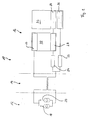
- a device according to the invention is generally designated 10. This includes a wheel speed sensor 12, a wiring 14, and a signal processing unit 16.
- the vehicle sensor 12 comprises two signal paths, namely a signal path 18, which delivers a "high" current of, for example, 14 mA, when the sensor 12 detects a specific event, for example an inductive excitation, and the signal path 20, which generates a "low” current of, for example, 7mA when the sensor 12 is in its quiescent state.
- the wheel speed sensor 12 is connected to the signal processing unit 16 via the wiring 14. This includes a power supply 22 for the wheel speed sensor 12, a first low-pass filter 24 and a second low-pass filter 26.
- the signal processing unit 10 includes an evaluation device 28, which interrogates certain characteristics of the output signal of the wheel speed sensor 12 obtained from the low-pass filter 24. This will be discussed in detail below.
- the power supply 22 for the wheel speed sensor 12 and the query filter 28 are combined to form an application-specific integrated circuit (ASIC) 30.
- ASIC application-specific integrated circuit
- the main processor 32 comprises a high-resolution timer 34 and an analog-to-digital converter 36.
- the timer 34 is connected to the evaluation device 28.
- the analog-to-digital converter 36 is connected to the low-pass filter 26.
- the device 10 according to the invention Fig.1 detected by the wheel speed sensor 12 a wheel speed and outputs a corresponding analog AC signal via the wiring 14 to the signal processing unit 16 from. This output signal is then first filtered through the low-pass filters 24 and 26 and subjected to further processing, which will be described below with reference to FIGS. 2 to 5 will be explained in more detail.
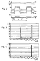
- Fig.2 shows different courses of the analog output signal of the speed sensor 12.
- the current intensity I s of the sensor 12 is plotted in mA over time.
- An ideal course of the output signal output by the rotational speed sensor 12 is designated 40.
- This waveform 40 shows essentially two discrete signal levels, namely a "low” level at 7mA and a "high” level at 14mA. Based on the period of the change of signal levels between 7mA and 14mA, the wheel speed can be determined.
- T which is divided into N equal time intervals ⁇ t, the output signal is sampled N times.
- a certain sample is obtained with a signal amplitude associated therewith, which corresponds to the respective signal level.
- Fig.2 shows further that due to interference or malfunction of the speed sensor 12, other deviating from the waveform 40 waveforms may result.
- the waveforms 42 and 44 due to disturbing influences in the vehicle electronics, a faulty power supply of the rotational speed sensor 12 or the like, although shifted in relation to the waveform 40 with respect to the occurring currents.
- shifted voltage signals 42 and 44 may already be required error detection. This can for example lead to a deactivation of various electronic systems for security reasons.
- Conventional systems can not do such error detection or only with a high level of hardware complexity in order to be able to perform a sampling according to the Shannon sampling theorem.
- Fig.2 also shows two further waveforms 46, 48, which are above or below certain threshold values 50, 52.
- Such highly displaced waveforms can be detected even with conventional systems, for example, by using threshold sensors that detect a short circuit or a line break.
- the output signal output by the rotational speed sensor 12 is sampled N times. This is done according to the flowchart of Figure 5 after starting the procedure according to step S1 in step S2. For example, at a discrete point in time t 1 , t 2 , etc., the current sensor current is detected. In this case, the amplitude of the sensor current is detected and an amplitude counter, to which an amplitude range encompassing this amplitude is assigned, is incremented by the value 1.
- the respective values of the amplitude counters are transformed into a histogram according to FIG Figure 3 entered.
- the respective counts n are plotted against the amplitude values.
- each amplitude value between 0 and 19 mA with an amplitude range of 0.5 mA each is assigned an amplitude counter.
- the polling of the current sensor current according to step S2 and the Entry into a histogram according to step S3 is performed N times. This means that a counter N is incremented after each query in step S4 and it is checked in step S5 whether a limit value, for example the value 1000 at a sampling frequency of 1000 Hz, has already been reached. If this is not achieved, the steps S2 to S5 are performed again. If the condition according to step S5 is fulfilled, however, the current measurement cycle is completed and it is possible to determine current from current levels from the histogram according to FIG Figure 3 respectively.
- Figure 3 further shows that during the measurement cycle samples in the amplitude range between 7 and 7.5 mA have occurred at a frequency of about 315 and samples in the amplitude range between 15 and 15.5 mA have occurred at a frequency of about 395. The remaining frequencies of samples with different amplitudes are significantly lower. The next smaller frequency is around 55.
- Figure 3 Now allows a simple determination of the two signal level indicative of the output signal 40 by each one amplitude value from the two amplitude ranges is used with the most frequently occurring during the measurement cycle samples as the signal level. This is done in step S6 of Figure 5 , The remaining samples result, for example, due to a scan during an ascending or falling edge or due to disturbing influences.
- Figure 4 shows a histogram corresponding to the histogram according to FIG Figure 3 deviates strongly.
- the frequency of samples in a measurement cycle is about 860 for amplitudes between 15.0 and 15.5 mA.
- the remaining samples with deviating amplitude occur with almost negligible frequency.
- Only the samples with an amplitude between 7.0 and 7.5 mA still occur at a frequency of about 40.
- a histogram accordingly Figure 4 results, for example, when the sampling rate N per measurement cycle largely coincides with the frequency of the output from the speed sensor 12 output signal. This means that a sampling of the output signal largely occurs every time this signal has reached a certain signal level, for example the "high" current. At other signal levels, scanning is comparatively rare according to the predetermined sampling rate.
- a histogram accordingly Figure 4 however, it can not be used to determine two current levels.
- step S7 the histogram can be correspondingly evaluated, that is, the current levels can be determined and used for further signal processing.
- step S8 the counter N is set to zero and (step S9) and the procedure is then terminated in step S10 so that it can be restarted for another measurement cycle. If, however, it is found in step S7 that not all predetermined conditions are met by the current levels determined from the histogram, an error handling procedure is initiated according to step S11, which may result, for example, in deactivation of a slip control system or the like.
- the invention thus shows a possibility which can be implemented relatively easily and which can be implemented, in particular, with little hardware outlay, to reliably monitor the function of a rotational speed sensor and to sample its output signal.
Landscapes
- Engineering & Computer Science (AREA)
- Transportation (AREA)
- Mechanical Engineering (AREA)
- Physics & Mathematics (AREA)
- General Physics & Mathematics (AREA)
- Regulating Braking Force (AREA)
- Transmission And Conversion Of Sensor Element Output (AREA)
- Measurement Of Current Or Voltage (AREA)
Abstract
Description
Die vorliegende Erfindung betrifft ein Verfahren nach dem Oberbegriff von Anspruch 1 und eine Vorrichtung nach dem Oberbegriff von Anspruch 15.The present invention relates to a method according to the preamble of
Derartige Verfahren und Vorrichtungen sind aus dem Stand der Technik bekannt. Für eine auf den gegenwärtigen Fahrzeugbetriebszustand abgestimmte Steuerung von Bremssystemen oder Schlupfregelsystemen neuerer Bauart ist es erforderlich, die Drehzahl einzelner Räder eines Kraftfahrzeugs permanent mit hinreichend hoher Genauigkeit zu überwachen. Hierfür werden Drehzahlsensoren verschiedener Bauart eingesetzt, wie beispielsweise induktive Sensoren, Hall-Sensoren oder dergleichen. Derartige Drehzahlsensoren liefern in der Regel ein pulsierendes Ausgangssignal mit Offset, welches sich im Idealfall zwischen lediglich zwei Stromwerten bewegt, einem niedrigen Stromwert, auch "Low"-Strom genannt, welcher beispielsweise bei 7mA liegt, und einem erhöhten Stromwert, auch "High"-Strom genannt, welcher, beispielsweise bei 14mA liegt. Der "Low"-Strom stellt sich beispielsweise dann ein, wenn der Sensor gerade kein Signal erfasst, wohingegen sich der "High"-Strom einstellt, wenn der Sensor ein Signal erfasst. Im Idealfall, d.h. bei einer Messung mit einer hochfrequenten Abtastung, erhält man eine Verteilung von Abtastwerten, welche sehr genau den tatsächlichen Verlauf des Ausgangssignals wiedergibt, wobei Signalflanken ebenfalls erfasst werden. Mit Hilfe statistischer Ansätze lassen sich dann diejenigen Abtastwerte ermitteln, deren Amplituden am häufigsten auftreten. Der Wert, der am häufigsten auftritt wird auch als "Modus" bezeichnet.Such methods and devices are known in the art. For control of brake systems or slip control systems of a newer type, coordinated with the current vehicle operating state, it is necessary to monitor the speed of individual wheels of a motor vehicle permanently with sufficiently high accuracy. For this purpose, speed sensors of various types are used, such as inductive sensors, Hall sensors or the like. Such speed sensors generally provide a pulsating output signal with offset, which moves in the ideal case between only two current values, a low current value, also called "low" current, which is for example 7mA, and an increased current value, also "high". Called current, which, for example, at 14mA. The "low" current, for example, turns on when the sensor is not detecting a signal, whereas the "high" current sets when the sensor detects a signal. Ideally, i. in a measurement with a high-frequency sampling, one obtains a distribution of samples which very accurately reflects the actual course of the output signal, wherein signal edges are also detected. Statistical approaches can then be used to determine those samples whose amplitudes occur most frequently. The value that occurs most often is also referred to as "mode".
Es hat sich jedoch gezeigt, dass im Betrieb eines Kraftfahrzeugs die Drehzahlerfassung durch verschiedene Störeinflüsse beeinträchtigt werden kann. So kann es durch einen unerwünschten Serienwiderstand in der Sensorleitung, durch Kurzschlüsse oder Komponenten mit beeinträchtigter Funktion zu einer Verschiebung der Signalpegel des Ausgangssignals kommen. Dies führt dazu, dass die Auswerteelektronik die Signalpegel nicht mehr richtig erkennen kann und nach einer Weiterverarbeitung möglicherweise falsche digitale Impulse weitergibt. In der Folge würde das Bremssystem oder Schlupfregelsystem falsche Raddrehzahlen verwenden, so dass es zu einer Fehlfunktion kommen könnte. Um derartige Fehler erkennen zu können, müssen aus dem Ausgangssignal jeweils beide Strompegel erfasst werden, nämlich der "Low"-Strom sowie der "High"-Strom, um sicherzustellen, dass die Auswerteelektronik diese Signalpegel richtig in digitale Signale umwandeln kann. Da es sich allerdings bei dem Ausgangssignal um ein Frequenzsignal handelt, müsste nach dem Abtasttheorem von Shannon die Abtastfrequenz mindestens doppelt so hoch sein wie die höchste Frequenz, die in dem abzutastenden Signal auftritt. Dadurch würde sich eine Abtastfrequenz ergeben, welche eine erhebliche Rechenleistung eines Prozessors benötigt. Entsprechende Prozessoren sind kostenintensiv in ihrer Anschaffung und verteuern daher das Gesamtsystem in unerwünschter Weise.However, it has been shown that during operation of a motor vehicle, the speed detection can be affected by various disturbances. Thus, an unwanted series resistance in the sensor line, short circuits or components with impaired function can lead to a shift in the signal level of the output signal. As a result, the transmitter will no longer be able to detect the signal levels correctly and may transmit false digital pulses after further processing. As a result, the braking system would or slip control system use incorrect wheel speeds, which could cause it to malfunction. In order to detect such errors, both current levels must be detected from the output signal, namely the "low" current and the "high" current, in order to ensure that the evaluation electronics can correctly convert these signal levels into digital signals. However, since the output signal is a frequency signal, according to Shannon's sampling theorem, the sampling frequency would have to be at least twice as high as the highest frequency occurring in the signal to be sampled. This would result in a sampling frequency, which requires a considerable computing power of a processor. Corresponding processors are expensive to purchase and therefore more expensive the overall system in an undesirable manner.
Aus der
Eine weitere Vorrichtung zur Messung der Geschwindigkeit eines beweglichen Körpers ist aus
Es ist eine Aufgabe der vorliegenden Erfindung, ein Verfahren und eine Vorrichtung der eingangs bezeichneten Art bereitzustellen, bei welchen eine niedrige Abtastrate ausreicht um Fehler bei der Erfassung der Sensorsignale schnell und zuverlässig zu erkennen.It is an object of the present invention to provide a method and apparatus of the type described in the beginning, in which a low sampling rate is sufficient to quickly and reliably detect errors in the detection of the sensor signals.
Diese Aufgabe wird durch ein Verfahren mit den Merkmalen des Anspruchs 1 und eine Vorrichtung mit den Merkmalen des Anspruchs 15 gelöst.This object is achieved by a method having the features of
Dabei gibt der Drehzahlsensor ein die aktuelle Drehzahl charakterisierendes Ausgangssignal aus und das Ausgangssignal des Drehzahlsensors wird abgetastet und nach Maßgabe dabei erhaltener Abtastwerte weiterverarbeitet. Zur Lösung der vorstehend genannten Aufgabe sieht die Erfindung ferner vor, dass das Ausgangssignal mit einer vorbestimmten Abtastrate über wenigstens einen Messzyklus abgetastet wird, dass jeweils die Amplitude von in dem Messzyklus erhaltenen Abtastwerten ermittelt wird und dass anhand der Häufigkeit des Auftretens von Abtastwerten mit innerhalb eines vorbestimmten Amplitudenbereichs liegender Amplitude wenigstens ein während des Messzyklus in dem Ausgangssignal auftretender Signalpegel ermittelt wird, wobei ein Signalpegel lediglich dann ermittelt wird, wenn die diesen bestimmenden Abtastwerte einen Mindestanteil aller in den Messzyklus ermittelten Abtastwerte aufweisen.In this case, the rotational speed sensor outputs an output signal characterizing the current rotational speed and the output signal of the rotational speed sensor is sampled and further processed in accordance with samples obtained thereby. To achieve the above object, the invention further provides that the output signal is sampled at a predetermined sampling rate over at least one measurement cycle, that in each case the amplitude of samples obtained in the measurement cycle is determined and that based on the frequency of occurrence of samples with amplitude lying within a predetermined amplitude range determines at least one signal level occurring during the measurement cycle in the output signal wherein a signal level is only determined if the samples determining it have a minimum proportion of all the sampled values determined in the measurement cycle.
Die Erfindung sieht somit vor, unabhängig von der maximalen Frequenz und gegenwärtigen Periodendauer des abgetasteten Ausgangssignals dieses mit einer vorbestimmten Abtastrate über einen Messzyklus bestimmter Dauer abzutasten. Dabei erhält man zeitdiskrete Abtastwerte verschiedener Amplitude als Messergebnis. Dieses Messergebnis wird dann in der Folge anhand der Häufigkeit des Auftretens von Abtastwerten mit innerhalb eines vorbestimmten Amplitudenbereichs liegender Amplitude untersucht. Anhand der ermittelten Häufigkeiten wird wenigstens ein Signalpegel ermittelt.The invention thus provides, regardless of the maximum frequency and current period of the sampled output signal to sample this with a predetermined sampling rate over a measuring cycle of certain duration. This results in discrete-time samples of different amplitude as a measurement result. This measurement result is then examined in the sequence on the basis of the frequency of the occurrence of samples with amplitude lying within a predetermined amplitude range. On the basis of the determined frequencies at least one signal level is determined.
In einer Weiterbildung der Erfindung ist vorgesehen, dass anhand der Häufigkeit des Auftretens von Abtastwerten mit innerhalb eines vorbestimmten Amplitudenbereichs liegender Amplitude je Messzyklus ein Histogramm erstellt wird, aus welchem der Signalpegel ermittelt wird. Die Erstellung eines Histogramms hat den Vorteil, dass sich dadurch in sehr schnell erfassbarer und anschaulicher Weise ein oder mehrere Signalpegel ermitteln lassen. Es werden beispielsweise der oder die Signalpegel mit der relativ größten Häufigkeit von Abtastwerten mit innerhalb eines vorbestimmten Amplitudenbereichs liegender Amplitude weiterverarbeitet.In a further development of the invention, it is provided that a histogram is generated from which the signal level is determined on the basis of the frequency of the occurrence of samples with amplitude lying within a predetermined amplitude range per measuring cycle. The advantage of creating a histogram is that one or more signal levels can be determined in a very fast and clear manner. By way of example, the signal level (s) having the relatively greatest frequency of sample values are further processed with amplitude lying within a predetermined amplitude range.
Zur Erfassung der Häufigkeiten ist in einer Erfindungsvariante vorgesehen, dass eine vorbestimmte Anzahl von Amplitudenzählern vorgesehen ist, wobei jedem Amplitudenzähler ein bestimmter Amplitudenbereich zugeordnet ist und wobei jeder Amplitudenzähler inkrementiert wird, wenn während des Messzyklus ein Abtastwert einen Amplitudenwert aufweist, der in den diesem zugeordneten Amplitudenbereich fällt. Hierbei kann vorgesehen sein, dass als Abtastwerte Stromwerte des Ausgangssignals ermittelt werden, und dass jedem Amplitudenzähler ein Stromwertbereich aus einem vorbestimmten Messbereich, vorzugsweise von 0 bis 19 mA, zugeordnet ist. Dabei können die Stromwertbereiche auch unterschiedlich groß bemessen sein, um den Messbereich stromwertabhängig unterschiedlich fein aufzuteilen. Um bei mehreren aufeinanderfolgenden Messzyklen vergleichbare Ergebnisse zu erhalten, kann in einer Weiterbildung der Erfindung vorgesehen sein, dass jeder Amplitudenzähler zu Beginn eines Messzyklus auf Null gesetzt wird.
Wie eingangs erläutert sieht die Erfindung vor, dass zur Abtastung des Ausgangssignals eine vorbestimmte die Abtastrate bestimmende Abtastfrequenz verwendet wird, welche unabhängig von der maximalen Frequenz und gegenwärtigen Periodendauer des Ausgangssignals ist. Um ein hinreichend genaues Abtastergebnis zu erhalten ist in einer Weiterbildung der Erfindung vorgesehen, dass eine Abtastfrequenz gewählt wird, die im Bereich von 100 bis 5000Hz, vorzugsweise im Bereich von 500 bis 2500Hz, besonders bevorzugt bei etwa 1000Hz liegt.In order to record the frequencies, a variant of the invention provides that a predetermined number of amplitude counters are provided, wherein each amplitude counter is assigned a specific amplitude range and wherein each amplitude counter is incremented if during the measuring cycle a sample has an amplitude value which is in the amplitude range assigned to it falls. In this case, provision can be made for current values of the output signal to be determined as samples, and for each amplitude counter to be assigned a current value range from a predetermined measuring range, preferably from 0 to 19 mA. In this case, the current value ranges can also be dimensioned differently large, in order to divide the measuring range depending on the current value with different fineness. In order to obtain comparable results with several successive measurement cycles, can in one Be further development of the invention provided that each amplitude counter is set to zero at the beginning of a measurement cycle.
As explained in the introduction, the invention provides that for sampling the output signal a predetermined sampling rate determining sampling frequency is used, which is independent of the maximum frequency and current period of the output signal. In order to obtain a sufficiently accurate sampling result, it is provided in a development of the invention that a sampling frequency is selected which is in the range of 100 to 5000 Hz, preferably in the range of 500 to 2500 Hz, more preferably approximately 1000 Hz.
Hinsichtlich der Dauer eines Messzyklus sieht die Erfindung beispielsweise vor, dass der Messzyklus eine Zeitspanne im Bereich von 0,1s bis 5s, vorzugsweise im Bereich von 0,5s bis 2,5s, bevorzugt um etwa 1s umfasst. Derartige Messzyklen erlauben eine hinreichend genaue Drehzahlermittlung bei zugleich kurzer Reaktionszeit des die erfasste Raddrehzahl verwendenden elektronischen Steuerungssystems des Kraftfahrzeugs.With regard to the duration of a measurement cycle, the invention provides, for example, that the measurement cycle comprises a time span in the range of 0.1 s to 5 s, preferably in the range of 0.5 s to 2.5 s, preferably by approximately 1 s. Such measuring cycles allow a sufficiently accurate speed determination at the same time short reaction time of the detected wheel speed using electronic control system of the motor vehicle.
Um zu vermeiden, dass unter starken Störeinflüssen eine Vielzahl von Signalpegeln ermittelt wird, welche dann im Nachhinein auf ihre Brauchbarkeit untersucht werden müssen, sieht das erfindungsgemäße Verfahren in einer Weiterbildung vor, dass bestimmte Bedingungen aufgestellt werden, deren Erfüllung nach Erhalt eines Abtastergebnisses überprüft werden. So ist erfindungsgemäß beispielsweise vorgesehen, dass ein Signalpegel lediglich dann ermittelt wird, wenn die diesen bestimmenden Abtastwerte einen Anteil von wenigstens 10%, vorzugsweise wenigstens 15%, aller in dem Messzyklus ermittelten Abtastwerte aufweisen. Signalpegel, deren diese bestimmenden Abtastwerte einen kleineren Anteil aufweisen werden somit beispielsweise als Rauschen oder dergleichen "aussortiert".In order to avoid that a large number of signal levels is determined under severe disturbances, which then have to be examined afterwards for their usefulness, the method according to the invention provides in a development that certain conditions are set up, the fulfillment of which is checked after receipt of a sampling result. Thus, according to the invention, for example, it is provided that a signal level is only determined if the samples determining it have a proportion of at least 10%, preferably at least 15%, of all the sampling values determined in the measuring cycle. Signal levels of which these determining samples have a smaller share are thus "sorted out", for example, as noise or the like.
Wie eingangs mit Bezug auf den Stand der Technik erläutert, kann es erforderlich sein, dass zwei Signalpegel erfasst werden müssen. Hierfür sieht das erfindungsgemäße Verfahren in einer Weiterbildung vor, dass diejenigen Signalpegel erfasst werden, deren Abtastwerte die beiden relativ am häufigsten auftretenden Amplitudenbereiche aufweisen. Alle übrigen ermittelten Signalpegel werden vorab ausgefiltert. Eine Weiterbildung der Erfindung sieht in diesem Zusammenhang vor, dass die beiden Signalpegel lediglich dann ermittelt werden, wenn die diese bestimmenden Abtastwerte zusammen einen Anteil von wenigstens 40%, vorzugsweise von wenigstens 50%, aller in dem Messzyklus ermittelten Abtastwerte aufweisen. Ist dieses Kriterium nicht erfüllt, so wird gemäß diesem Ausführungsbeispiel die entsprechende Messung als Fehlmessung angesehen. Ferner kann bei dem erfindungsgemäßen Verfahren vorgesehen sein, dass die beiden Signalpegel lediglich dann ermittelt bzw. zur Weiterverarbeitung freigegeben werden, wenn die Stromstärken um einen vorbestimmten Mindestdifferenzwert, vorzugsweise um wenigstens 1mA, voneinander abweichen. Durch diese Maßnahme lassen sich auch schwankende Amplitudenwerte zur Ermittlung eines bestimmten Signalpegels ausnutzen.As explained above with reference to the prior art, it may be necessary for two signal levels to be detected. For this purpose, the method according to the invention provides in a development that those signal levels are detected whose samples have the two relatively most frequently occurring amplitude ranges. All other detected signal levels are filtered out in advance. A development of the invention provides in this context that the two signal levels are only determined if the sampling values determining them together have a proportion of at least 40%, preferably of at least 50%, of all the sampling values determined in the measuring cycle. Is this Criterion is not met, then according to this embodiment, the corresponding measurement is regarded as a false measurement. Furthermore, it can be provided in the method according to the invention that the two signal levels are only determined or released for further processing if the current intensities deviate from one another by a predetermined minimum difference value, preferably by at least 1 mA. By means of this measure, fluctuating amplitude values can also be used to determine a specific signal level.
Die vorstehend angesprochenen Bedingungen können unterschiedlich logisch verknüpft sein. So ist es in einer Erfindungsvariante möglich, dass eine Erfüllung aller Bedingungen erforderlich ist, um einen Signalpegel zu ermitteln, man spricht in diesem Zusammenhang auch von einer konjunktiven Verknüpfung. Andere Erfindungsvarianten können hingegen vorsehen, dass lediglich eine der Bedingungen erfüllt sein muss, um einen Signalpegel zu ermitteln (disjunktive Verknüpfung) oder dass lediglich ein Teil der Bedingungen erfüllt sein muss.The above-mentioned conditions can be linked differently logically. Thus, it is possible in a variant of the invention that a fulfillment of all conditions is required to determine a signal level, one speaks in this context also of a conjunctive link. On the other hand, other variants of the invention may provide that only one of the conditions must be met in order to determine a signal level (disjunctive link) or that only a part of the conditions must be fulfilled.
In einer Weiterbildung der Erfindung kann vorgesehen sein, dass anhand des ermittelten Signalpegels eine Fehlerbehandlungsprozedur eingeleitet wird. Die Fehlerbehandlungsprozedur kann stets nach der Ermittlung eines Signalpegels oder nach Ablauf eines Messzyklus ablaufen und anhand von bestimmten Eigenschaften des ermittelten Signalpegels unterschiedliche Routinen starten. Beispielsweise kann durch die Fehlerbehandlungsprozedur ein entsprechendes elektronisches Steuerungssystem, wie beispielsweise ein Fahrzeugbremssystem oder ein Schlupfregelsystem, in einen Notbetriebsmodus umgeschaltet werden, in welchem Fehlfunktionen aufgrund mangelhafter Drehzahlermittlung ausgeschlossen werden. Die Fehlerbehandlungsprozedur kann erfindungsgemäß so eingerichtet werden, dass der Notbetriebsmodus beispielsweise erst nach Ablauf einer vorbestimmten Zeitperiode nach Ende des jeweiligen Messzyklus aktiviert wird. Die vorbestimmte Zeitperiode ist dabei derart bemessen, dass beispielsweise ein oder mehrere weitere Messzyklen abgewartet werden und deren Messergebnisse überprüft werden, bis schließlich sicher festgestellt werden kann, dass die Drehzahlerfassung dauerhaft zuverlässig oder fehlerhaft ist. Somit kann eine vorzeitige Aktivierung des Notbetriebsmodus vermieden werden. In der Fehlerbehandlungsprozedur kann die Plausibilität eines ermittelten Signalpegels ermittelt werden und ausgehend davon eine geeignete Routine, beispielsweise der Normalbetriebsmodus oder der Notbetriebsmodus, aktiviert werden.In one development of the invention, provision can be made for an error handling procedure to be initiated on the basis of the determined signal level. The error handling procedure can always run after the determination of a signal level or at the end of a measurement cycle and start different routines based on certain properties of the detected signal level. For example, by the error handling procedure, a corresponding electronic control system, such as a vehicle brake system or a slip control system, may be switched to an emergency operation mode in which malfunction due to inadequate speed detection is precluded. According to the invention, the error handling procedure can be set up in such a way that the emergency operating mode is activated, for example, only after a predetermined period of time has elapsed after the end of the respective measuring cycle. The predetermined time period is dimensioned such that, for example, one or more further measurement cycles are awaited and their measurement results are checked until finally it can be determined with certainty that the speed detection is permanently reliable or faulty. Thus, premature activation of the emergency mode can be avoided. In the error handling procedure, the plausibility of a determined signal level can be determined and, based thereon, a suitable routine, for example the normal operating mode or the emergency operating mode, can be activated.
In einer Weiterbildung des erfindungsgemäßen Verfahrens kann vorgesehen sein, dass die während des Messzyklus aufgetretenen Amplituden und die Häufigkeit des Auftretens von Abtastwerten mit innerhalb eines vorbestimmten Amplitudenbereichs liegender Amplitude zwischengespeichert werden.In a development of the method according to the invention, it can be provided that the amplitudes which occur during the measuring cycle and the frequency of the occurrence of samples are buffered with amplitude lying within a predetermined amplitude range.
Die Erfindung betrifft ferner eine Vorrichtung zum Erfassen von Drehzahlen, insbesondere Raddrehzahlen eines Rades eines Kraftfahrzeugs, mit einem Drehzahlsensor zur Erfassung eines die gegenwärtige Drehzahl beschreibenden Ausgangssignals, einer Abtasteinrichtung zum Abtasten des Ausgangssignals und einer Signalverarbeitungseinrichtung zur Weiterverarbeitung des von der Abtasteinrichtung abgetasteten Ausgangssignals. Die erfindungsgemäße Vorrichtung ist insbesondere zur Durchführung des vorstehend erörterten erfindungsgemäßen Verfahrens ausgebildet. Sie sieht erfindungsgemäß ferner vor, dass das Ausgangssignal mit einer vorbestimmten Abtastrate über wenigstens einen Messzyklus abgetastet wird, dass jeweils die Amplitude von in dem Messzyklus erhaltenen Abtastwerten ermittelt wird und dass anhand der Häufigkeit des Auftretens von Abtastwerten mit in einen vorbestimmten Amplitudenbereich fallender Amplitude wenigstens ein während des Messzyklus in dem Ausgangssignal auftretender Signalpegel ermittelt wird. Dabei kann die Abtasteinrichtung zum Ausgeben zeitdiskreter Abtastwerte ausgebildet sein. Ferner kann die Signalverarbeitungseinrichtung eine Zählereinrichtung zur Ermittlung der Häufigkeit des Auftretens von Abtastwerten mit innerhalb eines vorbestimmten Amplitudenbereichs liegender Amplitude während des Messzyklus umfassen. Diese Zählereinrichtung kann als Endloszähler ausgebildet sein, gleichermaßen ist es jedoch möglich, dass die Zählereinrichtung zu Beginn eines neuen Messzyklus auf einen Anfangswert, vorzugsweise auf "0", rücksetzbar ist.The invention further relates to a device for detecting rotational speeds, in particular wheel speeds of a wheel of a motor vehicle, having a rotational speed sensor for detecting an output signal describing the current rotational speed, a sampling device for sampling the output signal and a signal processing device for further processing the output signal sampled by the sampling device. The device according to the invention is designed in particular for carrying out the method according to the invention discussed above. It also provides according to the invention that the output signal is sampled at a predetermined sampling rate over at least one measurement cycle, that in each case the amplitude of samples obtained in the measurement cycle is determined, and at least one of the frequencies of occurrence of samples having amplitude falling within a predetermined amplitude range during the measurement cycle in the output signal occurring signal level is determined. In this case, the scanning device can be designed to output discrete-time samples. Furthermore, the signal processing device may comprise a counter device for determining the frequency of occurrence of samples with amplitude lying within a predetermined amplitude range during the measurement cycle. However, it is also possible for the counter device to be reset to an initial value, preferably to "0", at the beginning of a new measuring cycle.
Hinsichtlich der Ausgestaltung der Signalverarbeitungseinrichtung kann vorgesehen sein, dass diese einen Speicher zur Zwischenspeicherung der während des Messzyklus aufgetretenen Amplituden und der Häufigkeit des Auftretens von Abtastwerten mit innerhalb eines vorbestimmten Amplitudenbereichs liegender Amplitude aufweist. Ferner kann die erfindungsgemäße Vorrichtung, insbesondere deren Signalverarbeitungseinrichtung, wenigstens eine Auswerteeinrichtung zur Überprüfung vorbestimmter Eigenschaften des Ausgangssignals aufweisen. In einer Erfindungsvariante kann in diesem Zusammenhang vorgesehen sein, dass die Auswerteeinrichtung eine Ermittlung eines Signalpegels während eines Messzyklus dann zulässt, wenn die den Signalpegel bestimmenden Abtastwerte einen Anteil von wenigstens 10%, vorzugsweise von wenigstens 15%, an allen in dem Messzyklus erhaltenen Abtastwerte aufweisen. Zusätzlich oder alternativ kann die Erfindung vorsehen, dass die Auswerteeinrichtung während eines Messzyklus eine Ermittlung von lediglich einer vorbestimmten Anzahl von Signalpegeln, vorzugsweise von lediglich zwei Signalpegeln, dann zulässt, wenn die diese bestimmenden Abtastwerte zusammen einen Anteil von wenigstens 40%, vorzugsweise von wenigstens 50%, aller in dem Messzyklus erhaltenen Abtastwerte aufweisen. Schließlich kann in einer Weiterbildung der Erfindung vorgesehen sein, dass die Auswerteeinrichtung zusätzlich oder alternativ zu den vorstehend angesprochenen Funktionen eine Ermittlung einer Mehrzahl von Signalpegeln dann zulässt, wenn die diese bestimmenden Amplituden der Abtastwerte Stromstärken aufweisen, die um wenigstens 1mA voneinander abweichen.With regard to the configuration of the signal processing device, it can be provided that it has a memory for temporarily storing the amplitudes which occurred during the measuring cycle and the frequency of the occurrence of samples having amplitudes lying within a predetermined amplitude range. Furthermore, the device according to the invention, in particular its signal processing device, can have at least one evaluation device for checking predetermined properties of the output signal. In one variant of the invention, it can be provided in this connection that the evaluation device permits a determination of a signal level during a measurement cycle if the samples determining the signal level have a proportion of at least 10%, preferably at least 15%, of all the samples obtained in the measurement cycle , Additionally or alternatively, the invention may provide that the Evaluation device during a measurement cycle, a determination of only a predetermined number of signal levels, preferably only two signal levels, then permits, if the determining these samples together have a proportion of at least 40%, preferably at least 50%, of all samples obtained in the measurement cycle. Finally, it can be provided in a development of the invention that the evaluation device additionally or alternatively to the above-mentioned functions, a determination of a plurality of signal levels then allows if the determining these amplitudes of the samples current levels that differ by at least 1mA from each other.
Die Erfindung wird im folgenden anhand der beiliegenden Figuren beispielhaft erläutert. Es stellen dar:
- Fig.1
- eine schematische Darstellung der erfindungsgemäßen Vorrichtung in Form eines Blockschaltbilds;
- Fig.2
- einen Graph, welcher verschiedene Signalverläufe des Ausgangssignals wiedergibt;
- Fig.3
- ein Histogramm, welches die Verteilung von in einem Messzyklus erhaltenen Abtastwerten wiedergibt;
- Fig.4
- ein Histogramm ähnlich
Fig.3 welches eine fehlerhafte Messung zeigt und - Fig.5
- ein grobes Ablaufdiagramm des erfindungsgemäßen Verfahrens.
- Fig.1
- a schematic representation of the device according to the invention in the form of a block diagram;
- Fig.2
- a graph showing different waveforms of the output signal;
- Figure 3
- a histogram representing the distribution of samples obtained in one measurement cycle;
- Figure 4
- similar to a histogram
Figure 3 which shows a faulty measurement and - Figure 5
- a rough flow diagram of the method according to the invention.
In
Der Fahrzeugsensor 12 umfasst zwei Signalwege, nämlich einen Signalweg 18, welcher einen "High"-Strom von beispielsweise 14mA liefert, wenn der Sensor 12 ein bestimmtes Ereignis, beispielsweise eine induktive Erregung erfasst, und den Signalweg 20, welcher einen "Low"-Strom von beispielsweise 7mA liefert, wenn der Sensor 12 in seinem Ruhezustand ist. Der Raddrehzahlsensor 12 ist über die Verdrahtung 14 mit der Signalverarbeitungseinheit 16 verbunden. Diese umfasst eine Spannungsversorgung 22 für den Raddrehzahlsensor 12, ein erstes Tiefpassfilter 24 und ein zweites Tiefpassfilter 26. Ferner umfasst die Signalverarbeitungseinheit 10 eine Auswerteeinrichtung 28, welche bestimmte Eigenschaften des von dem Tiefpassfilter 24 erhaltenen Ausgangssignals des Raddrehzahlsensors 12 abfrägt. Darauf soll im Folgenden noch im Detail eingegangen werden.The
Die Spannungsversorgung 22 für den Raddrehzahlsensor 12 sowie das Abfragefilter 28 sind zu einem anwendungsspezifischen integrierten Schaltkreis (ASIC) 30 zusammengefasst. Dieser ist mit einem Hauptprozessor 32 verbunden. Der Hauptprozessor 32 umfasst einen hochauflösenden Zeitgeber 34 und einen Analog-Digital-Wandler 36. Der Zeitgeber 34 ist mit der Auswerteeinrichtung 28 verbunden. Der Analog-Digital-Wandler 36 ist mit dem Tiefpassfilter 26 verbunden.The
Die erfindungsgemäße Vorrichtung 10 gemäß
Erfindungsgemäß wird in dem Zeitintervall T das von dem Drehzahlsensor 12 ausgegebene Ausgangssignal N-fach abgetastet. Dies geschieht gemäß dem Ablaufdiagramm von
Die jeweiligen Werte der Amplitudenzähler werden in Schritt S3 in ein Histogramm gemäß
Um Messzyklen mit verwertbaren Messergebnissen von Messzyklen mit unbrauchbaren Messergebnissen zu unterscheiden, ist bei einer Ausführungsform der Erfindung vorgesehen, dass die Signalverarbeitungseinheit 16 das Ausgangssignal des Drehzahlsensors 12 auf die Erfüllung vorbestimmter Bedingungen überprüft. Dies erfolgt in Schritt S7. Derartige Bedingungen können sein:
- die zu den beiden zu bestimmenden Signalpegeln gehörenden Amplitudenzählerstände müssen jeweils einen Mindestanteil aller Messungen enthalten, beispielsweise 15% oder 20% oder mehr;
- die zu den zu ermittelnden Signalpegeln gehörenden Amplitudenzählerstände müssen höher sein als die Summe aller restlichen Zählerstände, welche sich aus Messungen während der Flanke oder durch Störeinflüsse ergeben,
- die Differenz zwischen den beiden Signalpegeln muss mindestens einen bestimmten Stromstärkenbetrag, beispielsweise 1mA, betragen.
- the amplitude counts belonging to the two signal levels to be determined must each contain a minimum proportion of all measurements, for example 15% or 20% or more;
- the amplitude counter values belonging to the signal levels to be determined must be higher than the sum of all remaining counter readings which result from measurements during the edge or due to interference,
- the difference between the two signal levels must be at least a certain amount of current, for example 1 mA.
Diese Bedingungen können logisch miteinander verknüpft sein, beispielsweise konjunktiv oder disjunktiv. Im vorliegenden Ausführungsbeispiel sind sie konjunktiv verknüpft, das heißt, es muss jede der Bedingungen erfüllt sein, um eine wirksame Signalpegelermittlung zuzulassen. Ergibt sich in Schritt S7 gemäß
Die Erfindung zeigt somit eine verhältnismäßig einfach durchzuführende und insbesondere mit geringem hardwaretechnischen Aufwand realisierbare Möglichkeit, zuverlässig die Funktion eines Drehzahlsensors zu überwachen und dessen Ausgangssignal abzutasten.The invention thus shows a possibility which can be implemented relatively easily and which can be implemented, in particular, with little hardware outlay, to reliably monitor the function of a rotational speed sensor and to sample its output signal.
Claims (23)
- Method of measuring erroneous sensor signals by the measuring of rotational speed, in particular a rotational speed of a wheel of a motor vehicle, by means of a speed sensor (12), wherein the speed sensor (12) produces an output signal characterizing the actual rotational speed and wherein the output signal of the speed sensor (12) is sampled at a predetermined sampling rate (N) over at least one measuring cycle (T) and in each case the amplitude of sampled values obtained in the measuring cycle (T) is determined, characterized in that from a rate (n) of occurrence of sampled values of an amplitude lying within a predetermined amplitude range at least one signal level occurring during the measuring cycle (T) in the output signal is determined, wherein a signal level is determined only when the sample values determining the signal level comprise a minimum fraction of all sampled values determined in the measuring cycle (T).
- Method according to claim 1, characterized in that
from the rate (n) of occurrence of sampled values of an amplitude lying within a predetermined amplitude range per measuring cycle (T) a histogram is created from which the signal level is determined. - Method according to claim 1 or 2, characterized in that
a predetermined number of amplitude counters is provided, wherein to each amplitude counter a specific amplitude range is assigned and wherein each amplitude counter is incremented when during the measuring cycle (T) a sampled value has an amplitude value that falls within the amplitude range assigned thereto. - Method according to claim 3, characterized in that
current values of the output signal are determined as sampled values and that a current value range from a predetermined measuring range, preferably from 0 to 19 mA, is assigned to each amplitudes counter. - Method according to claim 3 or 4, characterized in that
each amplitude counter is set to zero at the start of a measuring cycle (T). - Method according to one of the preceding claims, characterized in that
a sampling frequency determining the sampling rate is selected which is in the range of 100 to 5000Hz, preferably in the range of 500 to 2500Hz, particularly preferably at about 1000Hz. - Method according to one of the preceding claims, characterized in that
the measuring cycle (T) comprises a period of time in the range of 0,1s to 5s, preferably in the range of 0,5s to 2,5s, preferentially at about 1s. - Method according to one of the preceding claims, characterized in that
a signal level is determined only when the sampled values determining the signal level comprise a fraction of at least 10%, preferably at least 15%, of all of the sampled values determined in the measuring cycle (T). - Method according to one of the preceding claims, characterized in that
two signal levels are determined from the sampled values of the two relatively most frequently occurring amplitude ranges. - Method according to claim 8 and 9, characterized in that
the two signal levels are determined only when the sampled values determining the signal levels together comprise a fraction of at least 40%, preferably of at least 50%, of all the sampled values determined in the measuring cycle (T). - Method according to claim 9 or 10, characterized in that
the two signal levels are determined only when their current value differ from one another by a predetermined minimum differential value of preferably at least 1mA. - Method according to one of the preceding claims, characterized in that
on the basis of the determined signal level an error handling procedure is initiated. - Method according to claim 12, characterized in that
the error handling procedure initiates an emergency operating mode only after a predetermined period of time after the end of the measuring cycle (T) in dependence of the determined signal level. - Method according to one of the preceding claims, characterized in that
the amplitudes that have occurred during the measuring cycle (T) and the rate (n) of occurrence of sampled values of an amplitude lying within a predetermined amplitude range are stored temporarily - Apparatus (10) for measuring erroneous sensor signals by the measuring of rotational speed, in particular wheel speeds of a wheel of a motor vehicle, comprising:- a speed sensor (12) for measuring an output signal describing the actual rotational speed,- a sampling device (30) for sampling the output signal at a predetermined sampling rate (N) per measuring cycle (T) and- a signal processing device (32) for further processing of the output signal sampled by the sampling device (30) and for determining the amplitudes of sampled values obtained in the measuring cycle (T),characterized in that
the signal processing device (32) is adapted to determine from a rate (n) of occurrence of sampled values of an amplitude lying within a predetermined amplitude range at least one signal level occurring during the measuring cycle (T) in the output signal, wherein the signal processing device is designed to allow a determination of a signal level during the measuring cycle (T) when the sampled values determining the signal level comprise a minimum fraction of all sampled values comprised in the measuring cycle. - Apparatus (10) according to claim 15, characterized in that
the sampling device (30) is designed to output time-discrete sampled values. - Apparatus (10) according to claim 15 or 16, characterized in that
the signal processing device (32) comprises a counting device for determining the rate (n) of occurrence of sampled values of an amplitude lying within a predetermined amplitude range during the measuring cycle (T). - Apparatus (10) according to claim 17, characterized in that
the counting device is resettable, in particular to "0", to an initial value at the start of a new measuring cycle (T). - Apparatus (10) according to one of the claims 15 to 18, characterized in that the signal processing device (32) comprises a memory for temporarily storing the amplitudes that have occurred during the measuring cycle (T) and the rate (n) of occurrence of sampled values of an amplitude lying within a predetermined amplitude range.
- Apparatus (10) according to one of the claims 15 to 19, characterized in that
the signal processing device (32) comprises at least one evaluation device for checking predetermined properties of the output signal. - Apparatus (10) according to claim 20, characterized in that
the evaluation device allows a determination of a signal level during a measuring cycle (T) when the sampled values determining the signal level comprise a fraction of at least 10%, preferably of at least 15%, of all of the sampled values obtained in the measuring cycle (T). - Apparatus (10) according to claim 20 or 21, characterized in that
the evaluation device during a measuring cycle (T) allows a determination of only a predetermined number of signal levels, preferably of only two signal levels when the sampled values determining the signal levels together comprise a fraction of at least 40%, preferably of at least 50%, of all of the sampled values obtained in the measuring cycle (T). - Apparatus (10) according to one of the claims 20 to 22, characterized in that
the evaluation device allows a determination of a plurality of signal levels only when the amplitudes of the sampled values determining the signal levels comprise current values that differ from one another by at least a predetermined minimum differential value, preferably of at least 1mA.
Applications Claiming Priority (3)
| Application Number | Priority Date | Filing Date | Title |
|---|---|---|---|
| DE10312208A DE10312208B3 (en) | 2003-03-19 | 2003-03-19 | Counter for revolutions of wheel of road vehicle has sensor sending output signal to signal evaluation circuit with integrated circuit and main processor which monitor signal amplitude level |
| DE10312208 | 2003-03-19 | ||
| PCT/EP2004/002523 WO2004083871A1 (en) | 2003-03-19 | 2004-03-11 | Method and device for detecting a rotational speed, especially the rotational speed of the wheel of a vehicle |
Publications (2)
| Publication Number | Publication Date |
|---|---|
| EP1604213A1 EP1604213A1 (en) | 2005-12-14 |
| EP1604213B1 true EP1604213B1 (en) | 2011-12-21 |
Family
ID=32404451
Family Applications (1)
| Application Number | Title | Priority Date | Filing Date |
|---|---|---|---|
| EP04719418A Expired - Lifetime EP1604213B1 (en) | 2003-03-19 | 2004-03-11 | Method and device for detecting a rotational speed, especially the rotational speed of the wheel of a vehicle |
Country Status (6)
| Country | Link |
|---|---|
| US (1) | US7248991B2 (en) |
| EP (1) | EP1604213B1 (en) |
| JP (1) | JP4777875B2 (en) |
| AT (1) | ATE538390T1 (en) |
| DE (1) | DE10312208B3 (en) |
| WO (1) | WO2004083871A1 (en) |
Families Citing this family (8)
| Publication number | Priority date | Publication date | Assignee | Title |
|---|---|---|---|---|
| DE102006037619A1 (en) * | 2005-08-10 | 2007-03-22 | Continental Teves Ag & Co. Ohg | Circuit arrangement and method for monitoring wheel speed sensors in a motor vehicle control unit |
| US7328122B2 (en) * | 2005-11-18 | 2008-02-05 | Hamilton Sundstrand Corporation | Speed sensor |
| US7520573B2 (en) * | 2005-12-22 | 2009-04-21 | Kelsey-Hayes Company | Shadow zone fault detection |
| US8512325B2 (en) * | 2010-02-26 | 2013-08-20 | Covidien Lp | Frequency shifting multi mode ultrasonic dissector |
| EP3220550B1 (en) * | 2016-03-18 | 2019-06-05 | Rohde & Schwarz GmbH & Co. KG | Method and apparatus for analyzing a transmission signal |
| WO2019122384A2 (en) * | 2017-12-22 | 2019-06-27 | Continental Teves Ag & Co. Ohg | Rotational speed sensor with enhanced resolution and multiple switching thresholds |
| DE102020206566A1 (en) * | 2020-05-26 | 2021-12-02 | Robert Bosch Gesellschaft mit beschränkter Haftung | Sensor arrangement for a vehicle and multi-circuit braking system |
| FR3145529B1 (en) * | 2023-02-07 | 2025-06-13 | Hitachi Astemo France | BRAKE EMERGENCY CIRCUIT TRANSMITTING A SIGNAL REPRESENTATIVE OF WHEEL SPEED TO A BRAKE CONTROL UNIT |
Family Cites Families (10)
| Publication number | Priority date | Publication date | Assignee | Title |
|---|---|---|---|---|
| GB251003A (en) | 1925-01-20 | 1926-04-20 | Philip Warwick Robson | Improvements in and relating to steam generators |
| US4092853A (en) * | 1975-10-25 | 1978-06-06 | Robert Bosch Gmbh | Testing rotary movement-electrical signal transducer system, particularly for vehicle wheel anti-block transducer systems |
| JPS59196472A (en) * | 1983-04-23 | 1984-11-07 | Nissan Motor Co Ltd | Wheel acceleration/deceleration detector |
| GB2184304B (en) * | 1985-12-12 | 1989-10-11 | Rank Taylor Hobson Ltd | Velocity measuring apparatus |
| DE3721827A1 (en) * | 1987-07-02 | 1989-01-12 | Daimler Benz Ag | DEVICE FOR MEASURING THE FREQUENCY OF A SINE SIGNAL GENERATED BY A SIGNAL GENERATOR |
| JPH063406A (en) * | 1992-06-23 | 1994-01-11 | Fujitsu Ltd | Method and system for measurement of operational signal |
| JPH06309473A (en) * | 1993-04-27 | 1994-11-04 | Hioki Ee Corp | Waveform data collection method and same waveform data determination method |
| JP3626568B2 (en) * | 1997-01-17 | 2005-03-09 | 本田技研工業株式会社 | Control method in vehicle braking force control device |
| US6269317B1 (en) * | 1997-04-30 | 2001-07-31 | Lecroy Corporation | Self-calibration of an oscilloscope using a square-wave test signal |
| JPH11223639A (en) * | 1998-02-05 | 1999-08-17 | Unisia Jecs Corp | Rotation speed detector |
-
2003
- 2003-03-19 DE DE10312208A patent/DE10312208B3/en not_active Expired - Fee Related
-
2004
- 2004-03-11 JP JP2006504647A patent/JP4777875B2/en not_active Expired - Fee Related
- 2004-03-11 EP EP04719418A patent/EP1604213B1/en not_active Expired - Lifetime
- 2004-03-11 AT AT04719418T patent/ATE538390T1/en active
- 2004-03-11 WO PCT/EP2004/002523 patent/WO2004083871A1/en active Application Filing
-
2005
- 2005-09-19 US US11/230,077 patent/US7248991B2/en not_active Expired - Fee Related
Also Published As
| Publication number | Publication date |
|---|---|
| ATE538390T1 (en) | 2012-01-15 |
| WO2004083871A1 (en) | 2004-09-30 |
| JP2006520467A (en) | 2006-09-07 |
| JP4777875B2 (en) | 2011-09-21 |
| US7248991B2 (en) | 2007-07-24 |
| EP1604213A1 (en) | 2005-12-14 |
| US20060064274A1 (en) | 2006-03-23 |
| DE10312208B3 (en) | 2004-07-01 |
Similar Documents
| Publication | Publication Date | Title |
|---|---|---|
| EP1155330B1 (en) | Method for recognition of signal errors | |
| DE3817704C2 (en) | ||
| EP0745225B1 (en) | Error recognition process for sensors of speed of rotation | |
| EP1032846B1 (en) | Diagnostic device for recognizing short circuits or line interruptions of an inductive sensor | |
| EP0837801B1 (en) | Device for the recognition of electromagnetic interference | |
| DE3200529A1 (en) | ANTI-BLOCKING SYSTEM | |
| EP0500562B1 (en) | Circuit arrangement for processing the output from a rev counter | |
| EP1604213B1 (en) | Method and device for detecting a rotational speed, especially the rotational speed of the wheel of a vehicle | |
| DE69111300T2 (en) | Device and method for fault detection in a speed measuring system. | |
| EP2464956A1 (en) | Method for early detection of damage in a motor vehicle transmission | |
| DE3818699A1 (en) | DEVICE FOR DETERMINING A FUNCTIONAL FAILURE OF A TURN METER | |
| DE19820207A1 (en) | Antenna test arrangement for vehicle control system | |
| EP1084414B1 (en) | Method and device for checking the installation air gap of an active sensor | |
| DE19632457C1 (en) | Switching circuit for function monitoring for vehicle wheel RPM measuring sensor | |
| WO2016020036A1 (en) | Method for determining the duty factor of a pulse-width-modulated signal by means of a vehicle control unit, and vehicle control unit | |
| DE2841289A1 (en) | METHOD AND DEVICE FOR TESTING INDUCTIVE IMPULSE SENSORS | |
| DE19536006C2 (en) | Device for monitoring the speed of a wheel of a motor vehicle and at least one further state variable of the motor vehicle | |
| DE102018120408A1 (en) | METHOD AND SYSTEM FOR DETECTING A ROAD IMPACT EVENT AND FOR DIAGNOSING ANOMALIES IN CHASSIS COMPONENTS | |
| DE10145485B4 (en) | Method and device for diagnosing a sensor | |
| DE2142711C3 (en) | Signal test circuit for signals for which certain tolerance ranges are specified | |
| DE4035470C2 (en) | Processing analog signal in combine harvester - processing steep edge of signal to TTL compatible one, with signal counting | |
| DE4403218C2 (en) | Encoder | |
| WO2008037601A1 (en) | Method and device for testing a sensor, in particular a mono-directional or bi-directional acceleration sensor or yaw rate sensor | |
| DE10113556C2 (en) | Error detection method | |
| DE2547869C2 (en) | Method and circuit arrangement for checking the functionality of an electrical speed sensor |
Legal Events
| Date | Code | Title | Description |
|---|---|---|---|
| PUAI | Public reference made under article 153(3) epc to a published international application that has entered the european phase |
Free format text: ORIGINAL CODE: 0009012 |
|
| 17P | Request for examination filed |
Effective date: 20050908 |
|
| AK | Designated contracting states |
Kind code of ref document: A1 Designated state(s): AT BE BG CH CY CZ DE DK EE ES FI FR GB GR HU IE IT LI LU MC NL PL PT RO SE SI SK TR |
|
| AX | Request for extension of the european patent |
Extension state: AL LT LV MK |
|
| DAX | Request for extension of the european patent (deleted) | ||
| GRAP | Despatch of communication of intention to grant a patent |
Free format text: ORIGINAL CODE: EPIDOSNIGR1 |
|
| GRAS | Grant fee paid |
Free format text: ORIGINAL CODE: EPIDOSNIGR3 |
|
| GRAA | (expected) grant |
Free format text: ORIGINAL CODE: 0009210 |
|
| AK | Designated contracting states |
Kind code of ref document: B1 Designated state(s): AT BE BG CH CY CZ DE DK EE ES FI FR GB GR HU IE IT LI LU MC NL PL PT RO SE SI SK TR |
|
| REG | Reference to a national code |
Ref country code: GB Ref legal event code: FG4D Free format text: NOT ENGLISH |
|
| REG | Reference to a national code |
Ref country code: CH Ref legal event code: EP |
|
| REG | Reference to a national code |
Ref country code: AT Ref legal event code: REF Ref document number: 538390 Country of ref document: AT Kind code of ref document: T Effective date: 20120115 |
|
| REG | Reference to a national code |
Ref country code: IE Ref legal event code: FG4D |
|
| REG | Reference to a national code |
Ref country code: DE Ref legal event code: R096 Ref document number: 502004013169 Country of ref document: DE Effective date: 20120322 |
|
| REG | Reference to a national code |
Ref country code: NL Ref legal event code: VDEP Effective date: 20111221 |
|
| PG25 | Lapsed in a contracting state [announced via postgrant information from national office to epo] |
Ref country code: GR Free format text: LAPSE BECAUSE OF FAILURE TO SUBMIT A TRANSLATION OF THE DESCRIPTION OR TO PAY THE FEE WITHIN THE PRESCRIBED TIME-LIMIT Effective date: 20120322 Ref country code: SI Free format text: LAPSE BECAUSE OF FAILURE TO SUBMIT A TRANSLATION OF THE DESCRIPTION OR TO PAY THE FEE WITHIN THE PRESCRIBED TIME-LIMIT Effective date: 20111221 Ref country code: SE Free format text: LAPSE BECAUSE OF FAILURE TO SUBMIT A TRANSLATION OF THE DESCRIPTION OR TO PAY THE FEE WITHIN THE PRESCRIBED TIME-LIMIT Effective date: 20111221 Ref country code: NL Free format text: LAPSE BECAUSE OF FAILURE TO SUBMIT A TRANSLATION OF THE DESCRIPTION OR TO PAY THE FEE WITHIN THE PRESCRIBED TIME-LIMIT Effective date: 20111221 |
|
| PG25 | Lapsed in a contracting state [announced via postgrant information from national office to epo] |
Ref country code: CY Free format text: LAPSE BECAUSE OF FAILURE TO SUBMIT A TRANSLATION OF THE DESCRIPTION OR TO PAY THE FEE WITHIN THE PRESCRIBED TIME-LIMIT Effective date: 20111221 |
|
| REG | Reference to a national code |
Ref country code: IE Ref legal event code: FD4D |
|
| PG25 | Lapsed in a contracting state [announced via postgrant information from national office to epo] |
Ref country code: SK Free format text: LAPSE BECAUSE OF FAILURE TO SUBMIT A TRANSLATION OF THE DESCRIPTION OR TO PAY THE FEE WITHIN THE PRESCRIBED TIME-LIMIT Effective date: 20111221 Ref country code: CZ Free format text: LAPSE BECAUSE OF FAILURE TO SUBMIT A TRANSLATION OF THE DESCRIPTION OR TO PAY THE FEE WITHIN THE PRESCRIBED TIME-LIMIT Effective date: 20111221 Ref country code: IE Free format text: LAPSE BECAUSE OF FAILURE TO SUBMIT A TRANSLATION OF THE DESCRIPTION OR TO PAY THE FEE WITHIN THE PRESCRIBED TIME-LIMIT Effective date: 20111221 Ref country code: EE Free format text: LAPSE BECAUSE OF FAILURE TO SUBMIT A TRANSLATION OF THE DESCRIPTION OR TO PAY THE FEE WITHIN THE PRESCRIBED TIME-LIMIT Effective date: 20111221 Ref country code: BG Free format text: LAPSE BECAUSE OF FAILURE TO SUBMIT A TRANSLATION OF THE DESCRIPTION OR TO PAY THE FEE WITHIN THE PRESCRIBED TIME-LIMIT Effective date: 20120321 |
|
| PG25 | Lapsed in a contracting state [announced via postgrant information from national office to epo] |
Ref country code: RO Free format text: LAPSE BECAUSE OF FAILURE TO SUBMIT A TRANSLATION OF THE DESCRIPTION OR TO PAY THE FEE WITHIN THE PRESCRIBED TIME-LIMIT Effective date: 20111221 Ref country code: PT Free format text: LAPSE BECAUSE OF FAILURE TO SUBMIT A TRANSLATION OF THE DESCRIPTION OR TO PAY THE FEE WITHIN THE PRESCRIBED TIME-LIMIT Effective date: 20120423 Ref country code: PL Free format text: LAPSE BECAUSE OF FAILURE TO SUBMIT A TRANSLATION OF THE DESCRIPTION OR TO PAY THE FEE WITHIN THE PRESCRIBED TIME-LIMIT Effective date: 20111221 |
|
| BERE | Be: lapsed |
Owner name: LUCAS AUTOMOTIVE G.M.B.H. Effective date: 20120331 |
|
| PLBE | No opposition filed within time limit |
Free format text: ORIGINAL CODE: 0009261 |
|
| STAA | Information on the status of an ep patent application or granted ep patent |
Free format text: STATUS: NO OPPOSITION FILED WITHIN TIME LIMIT |
|
| PG25 | Lapsed in a contracting state [announced via postgrant information from national office to epo] |
Ref country code: MC Free format text: LAPSE BECAUSE OF NON-PAYMENT OF DUE FEES Effective date: 20120331 Ref country code: DK Free format text: LAPSE BECAUSE OF FAILURE TO SUBMIT A TRANSLATION OF THE DESCRIPTION OR TO PAY THE FEE WITHIN THE PRESCRIBED TIME-LIMIT Effective date: 20111221 |
|
| REG | Reference to a national code |
Ref country code: CH Ref legal event code: PL |
|
| 26N | No opposition filed |
Effective date: 20120924 |
|
| PG25 | Lapsed in a contracting state [announced via postgrant information from national office to epo] |
Ref country code: IT Free format text: LAPSE BECAUSE OF FAILURE TO SUBMIT A TRANSLATION OF THE DESCRIPTION OR TO PAY THE FEE WITHIN THE PRESCRIBED TIME-LIMIT Effective date: 20111221 |
|
| REG | Reference to a national code |
Ref country code: DE Ref legal event code: R097 Ref document number: 502004013169 Country of ref document: DE Effective date: 20120924 |
|
| PG25 | Lapsed in a contracting state [announced via postgrant information from national office to epo] |
Ref country code: LI Free format text: LAPSE BECAUSE OF NON-PAYMENT OF DUE FEES Effective date: 20120331 Ref country code: CH Free format text: LAPSE BECAUSE OF NON-PAYMENT OF DUE FEES Effective date: 20120331 Ref country code: BE Free format text: LAPSE BECAUSE OF NON-PAYMENT OF DUE FEES Effective date: 20120331 |
|
| PG25 | Lapsed in a contracting state [announced via postgrant information from national office to epo] |
Ref country code: ES Free format text: LAPSE BECAUSE OF FAILURE TO SUBMIT A TRANSLATION OF THE DESCRIPTION OR TO PAY THE FEE WITHIN THE PRESCRIBED TIME-LIMIT Effective date: 20120401 |
|
| REG | Reference to a national code |
Ref country code: AT Ref legal event code: MM01 Ref document number: 538390 Country of ref document: AT Kind code of ref document: T Effective date: 20120311 |
|
| PG25 | Lapsed in a contracting state [announced via postgrant information from national office to epo] |
Ref country code: FI Free format text: LAPSE BECAUSE OF FAILURE TO SUBMIT A TRANSLATION OF THE DESCRIPTION OR TO PAY THE FEE WITHIN THE PRESCRIBED TIME-LIMIT Effective date: 20111221 |
|
| PG25 | Lapsed in a contracting state [announced via postgrant information from national office to epo] |
Ref country code: AT Free format text: LAPSE BECAUSE OF NON-PAYMENT OF DUE FEES Effective date: 20120311 |
|
| PG25 | Lapsed in a contracting state [announced via postgrant information from national office to epo] |
Ref country code: TR Free format text: LAPSE BECAUSE OF FAILURE TO SUBMIT A TRANSLATION OF THE DESCRIPTION OR TO PAY THE FEE WITHIN THE PRESCRIBED TIME-LIMIT Effective date: 20111221 |
|
| PG25 | Lapsed in a contracting state [announced via postgrant information from national office to epo] |
Ref country code: LU Free format text: LAPSE BECAUSE OF NON-PAYMENT OF DUE FEES Effective date: 20120311 |
|
| PGFP | Annual fee paid to national office [announced via postgrant information from national office to epo] |
Ref country code: FR Payment date: 20140317 Year of fee payment: 11 |
|
| PGFP | Annual fee paid to national office [announced via postgrant information from national office to epo] |
Ref country code: GB Payment date: 20140327 Year of fee payment: 11 |
|
| PG25 | Lapsed in a contracting state [announced via postgrant information from national office to epo] |
Ref country code: HU Free format text: LAPSE BECAUSE OF FAILURE TO SUBMIT A TRANSLATION OF THE DESCRIPTION OR TO PAY THE FEE WITHIN THE PRESCRIBED TIME-LIMIT Effective date: 20040311 |
|
| GBPC | Gb: european patent ceased through non-payment of renewal fee |
Effective date: 20150311 |
|
| REG | Reference to a national code |
Ref country code: FR Ref legal event code: ST Effective date: 20151130 |
|
| PG25 | Lapsed in a contracting state [announced via postgrant information from national office to epo] |
Ref country code: GB Free format text: LAPSE BECAUSE OF NON-PAYMENT OF DUE FEES Effective date: 20150311 |
|
| PG25 | Lapsed in a contracting state [announced via postgrant information from national office to epo] |
Ref country code: FR Free format text: LAPSE BECAUSE OF NON-PAYMENT OF DUE FEES Effective date: 20150331 |
|
| REG | Reference to a national code |
Ref country code: DE Ref legal event code: R081 Ref document number: 502004013169 Country of ref document: DE Owner name: ZF ACTIVE SAFETY GMBH, DE Free format text: FORMER OWNER: LUCAS AUTOMOTIVE GMBH, 56070 KOBLENZ, DE |
|
| PGFP | Annual fee paid to national office [announced via postgrant information from national office to epo] |
Ref country code: DE Payment date: 20210329 Year of fee payment: 18 |
|
| REG | Reference to a national code |
Ref country code: DE Ref legal event code: R119 Ref document number: 502004013169 Country of ref document: DE |
|
| PG25 | Lapsed in a contracting state [announced via postgrant information from national office to epo] |
Ref country code: DE Free format text: LAPSE BECAUSE OF NON-PAYMENT OF DUE FEES Effective date: 20221001 |