EP1084414B1 - Method and device for checking the installation air gap of an active sensor - Google Patents
Method and device for checking the installation air gap of an active sensor Download PDFInfo
- Publication number
- EP1084414B1 EP1084414B1 EP99922089A EP99922089A EP1084414B1 EP 1084414 B1 EP1084414 B1 EP 1084414B1 EP 99922089 A EP99922089 A EP 99922089A EP 99922089 A EP99922089 A EP 99922089A EP 1084414 B1 EP1084414 B1 EP 1084414B1
- Authority
- EP
- European Patent Office
- Prior art keywords
- sensor
- supply voltage
- air gap
- air slot
- reduced
- Prior art date
- Legal status (The legal status is an assumption and is not a legal conclusion. Google has not performed a legal analysis and makes no representation as to the accuracy of the status listed.)
- Expired - Lifetime
Links
- 238000009434 installation Methods 0.000 title claims abstract description 12
- 238000000034 method Methods 0.000 title claims abstract description 12
- 238000012360 testing method Methods 0.000 claims abstract description 14
- 230000011664 signaling Effects 0.000 claims abstract description 6
- 230000003247 decreasing effect Effects 0.000 claims abstract description 5
- 230000008859 change Effects 0.000 claims description 4
- 238000012544 monitoring process Methods 0.000 claims description 4
- 230000035945 sensitivity Effects 0.000 claims description 3
- 230000009467 reduction Effects 0.000 claims description 2
- 238000003745 diagnosis Methods 0.000 claims 1
- 230000007257 malfunction Effects 0.000 claims 1
- 230000001419 dependent effect Effects 0.000 description 3
- 230000006870 function Effects 0.000 description 3
- 230000033001 locomotion Effects 0.000 description 3
- 238000013139 quantization Methods 0.000 description 3
- 230000005540 biological transmission Effects 0.000 description 2
- 238000010586 diagram Methods 0.000 description 2
- 238000005259 measurement Methods 0.000 description 2
- 238000011161 development Methods 0.000 description 1
- 230000018109 developmental process Effects 0.000 description 1
- 230000004069 differentiation Effects 0.000 description 1
- 238000012423 maintenance Methods 0.000 description 1
- 230000001105 regulatory effect Effects 0.000 description 1
- 238000012546 transfer Methods 0.000 description 1
- 230000028838 turning behavior Effects 0.000 description 1
Images


Classifications
-
- G—PHYSICS
- G01—MEASURING; TESTING
- G01P—MEASURING LINEAR OR ANGULAR SPEED, ACCELERATION, DECELERATION, OR SHOCK; INDICATING PRESENCE, ABSENCE, OR DIRECTION, OF MOVEMENT
- G01P21/00—Testing or calibrating of apparatus or devices covered by the preceding groups
- G01P21/02—Testing or calibrating of apparatus or devices covered by the preceding groups of speedometers
-
- G—PHYSICS
- G01—MEASURING; TESTING
- G01B—MEASURING LENGTH, THICKNESS OR SIMILAR LINEAR DIMENSIONS; MEASURING ANGLES; MEASURING AREAS; MEASURING IRREGULARITIES OF SURFACES OR CONTOURS
- G01B7/00—Measuring arrangements characterised by the use of electric or magnetic techniques
- G01B7/14—Measuring arrangements characterised by the use of electric or magnetic techniques for measuring distance or clearance between spaced objects or spaced apertures
-
- G—PHYSICS
- G01—MEASURING; TESTING
- G01P—MEASURING LINEAR OR ANGULAR SPEED, ACCELERATION, DECELERATION, OR SHOCK; INDICATING PRESENCE, ABSENCE, OR DIRECTION, OF MOVEMENT
- G01P1/00—Details of instruments
Definitions
- the magnetic sensitivity of the magnetoresistive bridge is in such a sensor from the bridge supply voltage dependent.
- the bridge reacts with about 2 mV per 1 V operating voltage to changes in magnetic field of 1 kA / m.
- the bridge voltage is internally on a Value of 5 V kept constant, so the sensitivity also remains constant.
Abstract
Description
Die Erfindung betrifft ein Verfahren sowie eine Vorrichtung zur Kontrolle oder zum Feststellen des Einbauluftspaltes zwischen einem aktiven Sensor und einem Encoder, wobei die maximale Größe des Luftspaltes (Grenzluftspalt), bei der ein störungsfreier Betrieb des Sensors noch gewährleistet ist, mindestens innerhalb eines Bereiches der Versorgungsspannung des Sensors von deren Höhe abhängig ist.The invention relates to a method and an apparatus for checking or determining the built-in air gap between an active sensor and an encoder, the maximum size of the air gap (limit air gap) at which Trouble-free operation of the sensor is still guaranteed is, at least within a range of the supply voltage of the sensor depends on their height.
Sensoren dieser Art finden insbesondere als Bewegungssensoren wie zum Beispiel zur Erfassung des Drehverhaltens eines Fahrzeugrades (Raddrehzahlsensoren) bei schlupfgeregelten Bremsen bzw. Antiblockiersystemen Anwendung. Die Drehbewegung wird dabei von einem in einem Encoder vorhandenen Polrad ausgeführt, durch das ein sich drehendes Magnetfeld erzeugt wird. Dieses Magnetfeld wird von dem Sensor erfaßt, dessen Meßwertaufnehmer z. B. eine magnetoresistive Brücke (AMR-Brücke) ist, die auf die Magnetfeldänderungen anspricht.Sensors of this type are used in particular as motion sensors such as to record the turning behavior of a Vehicle wheel (wheel speed sensors) with slip-controlled Brakes or anti-lock braking systems application. The rotary motion is from a magnet wheel in an encoder executed by which generates a rotating magnetic field becomes. This magnetic field is detected by the sensor whose transducer z. B. a magnetoresistive bridge (AMR bridge), which is responsive to the magnetic field changes.
Um eine störungsfreie Übertragung der Bewegungen von dem Encoder zu dem Sensor zu gewährleisten, muß sichergestellt sein, daß der Luftspalt niemals den Grenzluftspalt übersteigt. Darüber hinaus muß eine gewisse Mindestdifferenz zwischen dem tatsächlichen Luftspalt und dem Grenzluftspalt vorhanden sein, um zu gewährleisten, daß durch Bauelement-Toleranzen, Temperaturschwankungen und dynamische Verformungen oder eine gewisse Schwankung der Versorgungsspannung des Sensors der Grenzluftspalt auch vorübergehend nicht überschritten wird. Zur Kompensation der durch diese Schwankungen bewirkten Veränderungen des Luftspaltes weist der Sensor eine Triggerstufe auf, die der magnetoresistiven Brücke nachgeschaltet ist und mit der das Sensor-Ausgangssignal konstant gehalten wird.To ensure trouble-free transmission of the movements of the Ensuring encoder to the sensor must be ensured be that the air gap never exceeds the limit air gap. In addition, there must be a certain minimum difference between the actual air gap and the limit air gap be present to ensure that component tolerances, Temperature fluctuations and dynamic deformations or some fluctuation in the supply voltage the sensor, the limit air gap is also temporarily not is exceeded. To compensate for this Fluctuations caused changes in the air gap points the sensor has a trigger level that the magnetoresistive Bridge is connected downstream and with which the sensor output signal is kept constant.
Bei dieser Anordnung besteht jedoch das Problem, daß nach einer Montage des Sensors nicht überprüft werden kann, ob der Einbauluftspalt in ausreichendem Maße kleiner ist als der Grenzluftspalt, d.h. ob zwischen beiden eine Sicherheits-Mindestdifferenz besteht. Wenn das Sensor-Ausgangssignal vorhanden ist, bedeutet dies nur, daß der Luftspalt gegenwärtig den Grenzluftspalt nicht übersteigt. Der Luftspalt kann tatsächlich aber bereits so groß sein, daß durch eine ungünstige Kombination der oben genannten Toleranzbedingungen der Grenzluftspalt z.B. vorübergehend doch überschritten wird, so daß die Übertragung zwischen Encoder und Sensor zumindest gestört sein kann.With this arrangement, however, there is a problem that after mounting the sensor, it cannot be checked whether the built-in air gap is sufficiently smaller than the limit air gap, i.e. whether there is a minimum safety difference between the two consists. If the sensor output signal is present, it only means that the Air gap currently does not exceed the limit air gap. The air gap can actually be so big that by an unfavorable combination of the above Tolerance conditions of the limit air gap e.g. temporarily is exceeded, so that the transfer between Encoder and sensor can at least be disturbed.
Eine Messung des tatsächlichen Abstandes über die von dem Sensor empfangenen Signale ist aufgrund der in den Sensor eingebauten Triggerstufe nicht möglich, da diese ein konstantes Sensor-Ausgangssignal erzeugt, solange der Luftspalt den Grenzluftspalt nicht übersteigt.A measurement of the actual distance across from that Sensor received signals is due to the in the sensor built-in trigger level not possible, since this is a constant Sensor output signal generated as long as the Air gap does not exceed the limit air gap.
Der Erfindung liegt deshalb die Aufgabe zugrunde, nach einer Möglichkeit zu suchen, mit der bei einem Sensor der eingangs genannten Art der tatsächliche Einbauluftspalt und insbesondere die Differenz zwischen diesem und dem Grenzluftspalt kontrolliert oder festgestellt werden kann.The invention is therefore based on the object Possibility to search with a sensor of the type of the actual built-in air gap and in particular the difference between this and the limit air gap can be checked or ascertained.
Gelöst wird diese Aufgabe mit einem Verfahren der eingangs genannten Art, das sich auszeichnet durch folgende Verfahrensschritte:
- Reduzieren der Versorgungsspannung des Sensors auf mindestens einen Wert, durch den der Grenzluftspalt um jeweils ein gewünschtes Prüfmaß verkleinert wird und
- Vergleichen des mindestens einen Prüfmaßes mit einer gewünschten Differenz zwischen dem Grenzluftspalt und dem vorhandenen Luftspalt durch Erfassen einer Veränderung des Sensor-Ausgangssignals durch das Reduzieren der Versorgungsspannung, sowie Auswerten des Vergleichsergebnisses durch Signalisierung und / oder Abspeicherung.
- Reduce the supply voltage of the sensor to at least one value by means of which the limit air gap is reduced by a desired test dimension and
- Comparison of the at least one test dimension with a desired difference between the limit air gap and the existing air gap by detecting a change in the sensor output signal by reducing the supply voltage, and evaluating the comparison result by signaling and / or saving.
Die Aufgabe wird ferner mit einer Vorrichtung der eingangs genannten Art gelöst, die sich auszeichnet durch
- eine erste Einrichtung, mit der die versorgungsspannung des Sensors auf mindestens einen Wert reduzierbar ist, durch den der Grenzluftspalt um jeweils ein gewünschtes Prüfmaß verkleinert wird und
- eine zweite Einrichtung zum Vergleichen des mindestens einen Prüfmaßes mit einer gewünschten Differenz zwischen dem Grenzluftspalt und dem tatsächlichen Luftspalt durch Erfassen einer Veränderung des Sensor-Ausgangssignals durch die reduzierte Versorgungsspannung sowie zum Auswerten des Vergleichsergebnisses durch Signalisierung und / oder Abspeicherung.
- a first device with which the supply voltage of the sensor can be reduced to at least one value by means of which the limit air gap is reduced by a desired test dimension and
- a second device for comparing the at least one test dimension with a desired difference between the limit air gap and the actual air gap by detecting a change in the sensor output signal due to the reduced supply voltage and for evaluating the comparison result by signaling and / or storing.
Die unteransprüche haben vorteilhafte Weiterbildungen des Verfahrens bzw. der Vorrichtung zum Inhalt.The dependent claims have advantageous developments of Procedure or the device for content.
Weitere Einzelheiten, Merkmale und Vorteile der Erfindung
ergeben sich aus der folgenden Beschreibung einer bevorzugten
Ausführungsform anhand der Zeichnung. Es zeigt:
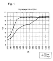
In Figur 1 sind die gemessenen hohen und niedrigen Sensor-Ausgangsspannungen Uahigh, Ualow in Abhängigkeit von der Versorgungsspannung Ub für einen aktiven Sensor einer schlupfgeregelten Bremsanlage (ABS) graphisch aufgetragen. Aus dieser Darstellung wird deutlich, daß bei einem Reduzieren der Versorgungsspanung Ub unter einen Nennwert von etwa 5 V das Ausgangssignal abfällt.In Figure 1, the measured high and low sensor output voltages Ua high , Ua low are plotted as a function of the supply voltage Ub for an active sensor of a slip-controlled brake system (ABS). It is clear from this illustration that when the supply voltage Ub is reduced below a nominal value of approximately 5 V, the output signal drops.
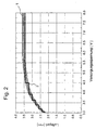
In Figur 2 ist der sich daraus ergebende physikalische Zusammenhang
zwischen der Versorgungsspannung eines Sensors
und dem maximalen Luftspalt zu einem ein Magnetfeld erzeugenden
Impulsrad eines Encoders dargestellt, bei dem gerade
noch eine störungsfreie Übertragung möglich ist
(Grenzluftspalt). Das Streuband 1 der Kurve repräsentiert
dabei die Meßwerte für eine Vielzahl von Sensorelementen in
Kombination mit dem gleichen Impulsrad. Das Streuband ermöglicht
eine Quantisierung in etwa sechs Unterscheidungsbereiche,
die als Stufen 2 eingezeichnet sind. Zur Prüfung
und Überwachung des Luftspaltes können eine oder mehrere
dieser Stufen verwendet werden, indem die Versorgungsspannung
entsprechend herabgesetzt wird.The resulting physical relationship is shown in FIG
between the supply voltage of a sensor
and the maximum air gap to a magnetic field generating
Pulse wheel of an encoder shown, with the
interference-free transmission is still possible
(Maximum air slot). The
In Figur 3a ist die Sensor-Ausgangsspannung Ua als Funktion der Größe des Luftspaltes bei einer versorgungsspannung des Sensors von 3,8 V aufgetragen. Die Darstellung zeigt, daß die Ausgangsspannung bis zu einem Luftspalt von etwa 2,9 mm konstant bleibt und dann abfällt. Figur 3b zeigt für die gleiche versorgungsspannung den Verlauf des Impuls/Pausenverhältnisses, das ab einem Luftspalt von etwa 2,7 mm abfällt. Aus beiden Darstellungen ergibt sich, daß der Grenzluftspalt bei dieser Versorgungsspannung bei etwa 2,7 mm erreicht ist, da bei größeren Luftspalten ein störungsfreier Betrieb nicht mehr gewährleistet ist.In Figure 3a, the sensor output voltage Ua is a function the size of the air gap at a supply voltage of Sensor of 3.8 V applied. The illustration shows that the output voltage up to an air gap of about 2.9 mm remains constant and then falls off. Figure 3b shows for the same supply voltage the course of the pulse / pause ratio, that from an air gap of about Drops 2.7 mm. From both representations it follows that the limit air gap at this supply voltage is approximately 2.7 mm is reached, since with larger air gaps a trouble-free Operation is no longer guaranteed.
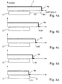
Die Figuren 4a bis 4e zeigen die sich ergebenden Verfügbarkeiten
des Sensor-Ausgangssignals 3, aufgetragen über der
Länge des Luftspaltes, und damit die virtuelle Verringerung
des Grenzluftspaltes 4a, 4b, 4c, 4d, 4e bei abnehmender
Versorgungsspannung des Sensors. Außerdem ist in Relation
dazu jeweils der Nenntoleranzbereich 5 des Luftspaltes eingezeichnet,
der auf Grund von Einbautoleranzen, dynamischen
Verformungen, Temperaturschwankungen usw. vorhanden sein
muß. Zwischen dem größten, unter diesen Gesichtspunkten anzunehmenden
tatsächlichen Luftspalt und dem Grenzluftspalt
sollte eine Sicherheits-Mindestdifferenz Dd
(Luftspaltreserve) bestehen. Die Größe des Nenntoleranzbereiches
korrespondiert im übrigen mit der Nennbetriebsspannung
des Sensors, die gemäß Figur 2 mindestens etwa 5 V beträgt. Figures 4a to 4e show the resulting availabilities
of the
Im Rahmen der möglichen Quantisierung kann der Grenzluftspalt und damit die Mindestdifferenz Dd schrittweise durch Absenken der versorgungsspannung des Sensors vermindert werden, bis er gemäß Figur 4e den Nenntoleranzbereich unterschreitet. Die in den Figuren 4a bis 4e eingetragenen Betriebsspannungen entsprechend dabei den Quantisierungsschritten gemäß Figur 2, wobei Figur 4 diese Schritte jedoch nicht maßstäblich wiedergibt.Within the scope of the possible quantization, the limit air gap and thus the minimum difference Dd gradually reduced by lowering the sensor supply voltage until it reaches the nominal tolerance range according to FIG. 4e below. The entered in Figures 4a to 4e Operating voltages according to the quantization steps according to Figure 2, but Figure 4, these steps not to scale.
Senkt man die Versorgungsspannung des Sensors bis auf den
in Figur 4e gezeigten Wert von 3,4 V ab, so ist es möglich,
daß das Sensor-Ausgangssignal aussetzt, wenn der tatsächliche
Einbauluftspalt gerade am oberen Ende 6 des Nenntoleranzbereiches
5 liegt, da in diesem Fall der Luftspalt größer
ist, als der Grenzluftspalt.If you lower the supply voltage of the sensor to
value of 3.4 V shown in FIG. 4e, it is possible
that the sensor output signal interrupts when the actual
Installation air gap just at the
Auf diese Weise kann also überprüft werden, ob sich der
tatsächliche Einbauluftspalt im Bereich des Nenntoleranzbereiches
5 bewegt oder schon so groß ist, daß er relativ nahe
am Grenzluftspalt liegt. Dies kann zum Beispiel dann der
Fall sein, wenn durch einen fehlerhaften Einbau der Nenntoleranzbereich
5 überschritten wurde. Das Sensorsignal würde
dann bereits bei einer Absenkung der Versorgungsspannung
des Sensors auf einen wert gemäß Figur 4c oder 4d aussetzen.In this way it can be checked whether the
actual air gap in the area of the
Durch die quantitative Zuordnung zwischen der Versorgungsspannung und dem Grenzluftspalt, die in Figur 2 dargestellt ist, kann auch ermittelt werden, wie groß der Einbauluftspalt tatsächlich ist, bzw. ob sich die Größe des Einbauluftspaltes um ein gewünschtes Mindestmaß von der Größe des Grenzluftspaltes bei der Nenn-Versorgungsspannung des Sensors unterscheiden. Diese Differenz würde in Abhängigkeit von der vorgesehenen Anwendung des Sensors zum Beispiel im Hinblick auf dynamische Verformungen des Luftspaltes festgelegt werden.Through the quantitative assignment between the supply voltage and the boundary air gap shown in Figure 2 the size of the built-in air gap can also be determined is actual, or whether the size of the built-in air gap by a desired minimum size of the limit air gap at the nominal supply voltage of the Differentiate sensors. This difference would be dependent from the intended application of the sensor, for example with regard to dynamic deformations of the air gap be determined.
Figur 5 zeigt ein Prinzipschaltbild einer erfindungsgemäßen Vorrichtung 7 zur Kontrolle und zum Feststellen des Einbauluftspaltes eines aktiven Sensors S, der von einem Encoder E beaufschlagt wird. Eine solche Steuereinheit findet insbesondere in einer schlupfgeregelten Bremsanlage zur Überwachung der Einbaulage des Sensors für die Raddrehzahl Anwendung.Figure 5 shows a schematic diagram of an inventive Device 7 for checking and determining the built-in air gap an active sensor S by an encoder E is applied. Such a control unit takes place in particular in a slip-controlled brake system for monitoring the installation position of the sensor for the wheel speed application.
Der Encoder E beinhaltet im allgemeinen ein Polrad (Impulsrad), durch dessen Drehung ein Magnetfeld mit wechselnder Polarität erzeugt wird. Zur Erfassung der Magnetfeldänderungen weist der Sensor S zum Beispiel eine magnetoresistive Brücke (AMR-Brücke) mit nachgeschalteter Verstärkeranordnung und Triggerstufe auf, deren Ausgangssignale in zwei geregelte Konstantströme mit entsprechend der Drehung des Polrades wechselnder Polarität umgesetzt werden. Die sensorsinterne Triggerstufe bewirkt, daß das Sensor-Ausgangssignal zumindest so lange luftspaltunabhängig konstant bleibt, wie die Versorgungsspannung des Sensors innerhalb des Nennspannungsbereiches liegt und der Luftspalt d den maximalen Grenzwert (Grenzluftspalt) nicht überschreitet.The encoder E generally contains a magnet wheel (Impulse wheel), by rotating a magnetic field with changing Polarity is generated. To record changes in the magnetic field For example, the sensor S has a magnetoresistive one Bridge (AMR bridge) with a downstream amplifier arrangement and trigger level, whose output signals in two regulated constant currents with the corresponding Rotation of the magnet wheel of changing polarity can be implemented. The internal trigger stage causes the sensor output signal independent of the air gap at least as long remains constant, like the supply voltage of the sensor is within the nominal voltage range and Air gap d does not meet the maximum limit (limit air gap) exceeds.
Die magnetische Empfindlichkeit der magnetoresistiven Brükke ist bei einem solchen Sensor von der Brücken-Versorgungsspannung abhängig. Bei einer bekannten Sensorelementfamilie reagiert die Brücke zum Beispiel mit etwa 2 mV pro 1 V Betriebsspannung auf Magnetfeldänderungen von 1kA/m. Innerhalb des spezifizierten Versorgungsspannungsbereiches des Sensors wird die Brückenspannung intern auf einem Wert von 5 V konstant gehalten, so daß die Empfindlichkeit ebenfalls konstant bleibt.The magnetic sensitivity of the magnetoresistive bridge is in such a sensor from the bridge supply voltage dependent. In a known sensor element family for example, the bridge reacts with about 2 mV per 1 V operating voltage to changes in magnetic field of 1 kA / m. Within the specified supply voltage range of the sensor, the bridge voltage is internally on a Value of 5 V kept constant, so the sensitivity also remains constant.
Die Schaltung 7 umfaßt im einzelnen einen Ausgang A, an dem
die Versorgungsspannung für den Sensor S anliegt, sowie einen
Eingang B, über den die Sensor-Ausgangssignale zugeführt
werden. Mit dem Eingang B ist ein RC-Glied sowie ein
Eingangsverstärker 8 verbunden. Daran schließt sich ein Sequenzkomparator
D an, der über eine Statusleitung 9 mit einer
Rechnereinheit 10 mit Diagnosespeicher. 15 verbunden
ist. Mit einem Ausgang der Rechnereinheit 10 ist über eine
Steuerleitung 11 ein Steuereingang eines Umschalters 12
verbunden. An einem ersten Eingang des Umschalters 12 liegt
eine erste Spannungsquelle 13, an einem zweiten Eingang eine
zweite Spannungsquelle 14 an. Der Ausgang des Umschalters
12 ist mit dem Ausgang A der Schaltung 7 verbunden.The circuit 7 includes an output A, at which
the supply voltage for sensor S is present, as well as one
Input B, through which the sensor output signals are fed
become. With the input B there is an RC element as well as a
Der am Eingang B der Schaltung 7 anliegende Strom erzeugt
an dem Widerstand R einen Spannungsabfall, der dem Eingang
des Verstärkers 8 zugeführt wird. Mit dem Sequenzkomparator
D wird das verstärkte Eingangssignal auf Signalaussetzer
überwacht, indem zum Beispiel das Tastverhältnis durch Auszählen
und Vergleichen der Anteile mit hohem und niedrigen
Pegel ausgewertet wird. Der Sequenzkomparator D erzeugt ein
erstes Statussignal, wenn das Tastverhältnis einem störungsfreien
Betrieb entspricht läßt und ein zweites Statussignal,
wenn sich das Tastverhältnis aufgrund von
Signalaussetzern ändert. Die Statussignale werden der Rechnereinheit
10 zu Diagnosezwecken zugeführt und gegebenenfalls
in dem Diagnosespeicher 15 abgespeichert. The current present at input B of circuit 7 generates
across the resistor R a voltage drop that corresponds to the input
of the
Wenn im Zuge einer Wartung oder nach einem Einbau des Sensors
dessen Einbaulage kontrolliert werden soll, kann durch
eine externes Signal, das der Rechnereinheit 10 zugeführt
wird, eine Überwachungsroutine gestartet werden. Dabei wird
dem Sensor zunächst die im Nennspannungsbereich liegende
Versorgungsspannung VI der ersten Spannungsquelle 13 zugeführt,
indem der Umschalter 12 über die Steuerleitung 11
entsprechend angesteuert wird.If in the course of maintenance or after installing the sensor
the installation position of which should be checked can by
an external signal that is supplied to the computer unit 10
a monitoring routine will be started. Doing so
the sensor is initially in the nominal voltage range
Supply voltage VI supplied to the
Wenn sich der Encoder E dreht und ein Sensorsignal vorhanden
ist, übermittelt der Sequenzkomparator D das erstes
Statussignal an die Rechnereinheit 10. Durch Erzeugung des
Schaltsignals auf der Steuerleitung 11 wird dann der Umschalter
12 betätigt, so daß die von der zweiten Spannungsquelle
14 erzeugte zweite Versorgungsspannung V2 an den
Sensor S angelegt wird. Die zweite Versorgungsspannung V2
kann in Abhängigkeit davon, mit welcher Genauigkeit die
Einbaulage überprüft werden soll, auf einen oder mehrere
der in den Figuren 4b bis 4e gezeigten Werte eingestellt
werden. Insbesondere kann durch stufenweises Absenken der
zweiten Versorgungsspannung V2 festgestellt werden, wie
groß die Differenz Dd zwischen dem vorhandenen Luftspalt
und dem Grenzluftspalt bei der Nenn-Versorgungsspannung ist
und ob diese Differenz einen gewünschten Sicherheits-Mindestwert
aufweist.When encoder E rotates and a sensor signal is present
the sequence comparator D transmits the first
Status signal to the
Wenn zum Beispiel das Sensorssignal bereits bei einer zweiten Versorgungsspannung V2 von 3,9 V nicht mehr vorhanden ist, so bedeutet dies unter Zugrundelegung der Meßwerte gemäß Figur 2, daß die Differenz weniger als 0,5 mm beträgt. Der Abstand des Sensors S von Encoder E sollte somit verringert werden, um das Risiko von Ausfällen bei dynamischen Verformungen oder Temperaturschwankungen o.ä. zu vermindern.If, for example, the sensor signal is already at a second Supply voltage V2 of 3.9 V no longer exists is based on the measured values according to Figure 2 that the difference is less than 0.5 mm. The distance between sensor S and encoder E should therefore be reduced to reduce the risk of failure in dynamic Deformations or temperature fluctuations or similar to diminish.
Wenn andererseits das Sensorsignal auch bei Anliegen einer
zweiten Versorgungsspannung V2 von 3,4 V (Figur 4e) noch
vorhanden ist, bedeutet dies, daß sich die Einbaulage des
Sensors innerhalb des Nenntoleranzbereiches 5 befindet und
darüberhinaus auch einen gewissen Mindestabstand von dessen
oberem Ende aufweist. Die Einbaulage des Sensors dürfte in
diesem Fall optimal sein.On the other hand, if the sensor signal is present even when a
second supply voltage V2 of 3.4 V (Figure 4e) still
is present, this means that the installation position of the
Sensor is within the
Die zweite Versorgungsspannung V2 kann vorzugsweise programmgesteuert mit einem D/A-Wandler erzeugt bzw. eingestellt werden.The second supply voltage V2 can preferably be program-controlled generated or set with a D / A converter become.
Die Meßergebnisse können zur Protokollierung in dem Diagnosespeicher
15 abgelegt werden. Insbesondere können auch die
Zusammenhänge zwischen der Verkleinerung des Grenzluftspaltes
und der Versorgungsspannung gemäß der Darstellung in
Figur 2 für eine Mehrzahl von spezifischen Sensor/Impulsrad-Kombinationen
zum Beispiel an der Vorder- und
Hinterachse eines Fahrzeugs für eine repräsentative Anzahl
von verschiedenen Kombinationen ermittelt und als Kenngrößen
in dem Diagnosespeicher 15 abgespeichert werden.The measurement results can be stored in the diagnostic memory for logging
15 are filed. In particular, the
Relationships between the narrowing of the boundary air gap
and the supply voltage as shown in
Figure 2 for a plurality of specific sensor / pulse wheel combinations
for example on the front and
Rear axle of a vehicle for a representative number
determined from various combinations and as parameters
can be stored in the
Claims (10)
- Method for checking or determining the installation air slot between an active sensor and an encoder, wherein the maximum size of the air slot (maximum air slot) which still ensures trouble-free operation of the sensor depends on the level of the supply voltage of the sensor at least within a range of said supply voltage,
characterized by the following method steps:reducing the supply voltage of the sensor to at least one value by which the maximum air slot is each time decreased by a desired test dimension, andcomparing the at least one test dimension with a desired difference between the maximum air slot and the existing air slot by determining a variation of the sensor output signal by the reduction of the supply voltage, as well as evaluating the comparison result by signalling and/or storing. - Method as claimed in claim 1,
characterized in that the supply voltage fed to the sensor is stepwise reduced to a multitude of values which correspond each time to a decrease of the maximum air slot by a predetermined test dimension until trouble-free operation of the sensor is at least temporarily no longer possible, and in that signalling is then generated and/or stored. - Method as claimed in claim 1,
characterized in that the supply voltage fed to the sensor is decreased by a value that corresponds to a predefinable test dimension, and it is then determined whether trouble-free operation of the sensor is still ensured. - Method as claimed in any one of the preceding claims,
characterized in that the method is automatically performed in defined intervals by a program control of a slip-controlled vehicle brake system. - Device for checking or determining the installation air slot between an active sensor and an encoder, wherein the maximum size of the air slot (maximum air slot) which still ensures trouble-free operation of the sensor depends on the level of the supply voltage of the sensor at least within a range of said supply voltage,
characterized bya first means (10, 12, 14) by which the supply voltage of the sensor (S) can be reduced to at least one value by which the maximum air slot is decreased each time by a desired test dimension, anda second means (D) for comparing the at least one test dimension with a desired difference between the maximum air slot and the actual air slot (d) by sensing a variation of the sensor output signal caused by the reduced supply voltage (V2) as well as for evaluating the comparison result by signalling and/or storing. - Device as claimed in claim 5,
characterized in that the sensor (S) includes a pick-up for measuring data that reacts to a change in the magnetic field, such as a magneto-resistive bridge with an amplifier and trigger circuit connected downstream thereof, and in that the first means permits reducing the supply voltage to a value (V2) at which the sensitivity of the bridge is reduced, however, the operation of the amplifier circuit is still maintained. - Device as claimed in claim 5 or 6,
characterized in that there is provision of a first voltage source (13) for generating a nominal supply voltage (VI), and the first means includes a second voltage source (14) for generating the reduced supply voltage (V2) and a commutator (12) controlled by a computer unit (10) for alternatively applying the first or the second voltage source to the sensor (S). - Device as claimed in any one of claims 5 to 7,
characterized in that the second means includes a sequence comparator (D) for monitoring the sensor output signals with respect to malfunctions or signal interruptions. - Device as claimed in any one of claims 5 to 8,
characterized in that a diagnosis memory (15) is provided to store the comparison results. - Device as claimed in any one of claims 5 to 9,
characterized in that the device is configured as a test device by which the sensors of a slip-controlled vehicle brake system can be tested as regards the correct installation position.
Applications Claiming Priority (5)
| Application Number | Priority Date | Filing Date | Title |
|---|---|---|---|
| DE19816180 | 1998-04-14 | ||
| DE19816180 | 1998-04-14 | ||
| DE19912877 | 1999-03-23 | ||
| DE19912877A DE19912877A1 (en) | 1998-04-14 | 1999-03-23 | Method and device for checking the built-in air gap of an active sensor |
| PCT/EP1999/002364 WO1999053327A1 (en) | 1998-04-14 | 1999-04-08 | Method and device for checking the installation air gap of an active sensor |
Publications (2)
| Publication Number | Publication Date |
|---|---|
| EP1084414A1 EP1084414A1 (en) | 2001-03-21 |
| EP1084414B1 true EP1084414B1 (en) | 2004-11-03 |
Family
ID=26045424
Family Applications (1)
| Application Number | Title | Priority Date | Filing Date |
|---|---|---|---|
| EP99922089A Expired - Lifetime EP1084414B1 (en) | 1998-04-14 | 1999-04-08 | Method and device for checking the installation air gap of an active sensor |
Country Status (5)
| Country | Link |
|---|---|
| US (1) | US6504360B1 (en) |
| EP (1) | EP1084414B1 (en) |
| JP (1) | JP4703004B2 (en) |
| DE (2) | DE19912877A1 (en) |
| WO (1) | WO1999053327A1 (en) |
Families Citing this family (9)
| Publication number | Priority date | Publication date | Assignee | Title |
|---|---|---|---|---|
| JP4120425B2 (en) * | 2003-02-28 | 2008-07-16 | 株式会社ジェイテクト | Rotation angle detection device and torque detection device |
| DE10347117B4 (en) * | 2003-10-10 | 2007-07-12 | Knorr-Bremse Systeme für Nutzfahrzeuge GmbH | Electronic circuit arrangement for the optional connection of speed sensors, in particular for commercial vehicles |
| DE102008027221A1 (en) * | 2008-06-06 | 2009-12-10 | Continental Teves Ag & Co. Ohg | Method for determining at least one first internal parameter of a sensor |
| DE102011103250B4 (en) * | 2011-06-03 | 2014-09-18 | Iav Gmbh Ingenieurgesellschaft Auto Und Verkehr | Device for monitoring the installation position of sensors |
| DE102012011602B4 (en) * | 2012-06-12 | 2022-02-10 | Volkswagen Aktiengesellschaft | Method and device for checking the installation of a sensor device |
| DE102013000205A1 (en) * | 2013-01-08 | 2014-07-10 | Wabco Gmbh | Control unit for controlling a brake system of a vehicle, speed sensor assembly, brake system and vehicle so and thus feasible method for speed sensing |
| DE102014216207B4 (en) * | 2014-08-14 | 2016-06-30 | Saf-Holland Gmbh | braking device |
| CN107192852A (en) * | 2017-06-30 | 2017-09-22 | 宁波佳明测控技术有限公司 | A kind of contactless testing device of speed sensor |
| CN111351963A (en) * | 2018-12-20 | 2020-06-30 | 陆博汽车电子(曲阜)有限公司 | Position adjusting method and device of wheel speed sensor and testing equipment thereof |
Family Cites Families (9)
| Publication number | Priority date | Publication date | Assignee | Title |
|---|---|---|---|---|
| DE6940893U (en) | 1969-10-21 | 1970-01-22 | Bernhard Klaus Schreiber | SPORTS EQUIPMENT |
| DE3941473A1 (en) | 1989-12-15 | 1991-06-20 | Bosch Gmbh Robert | METHOD AND DEVICE FOR CHECKING A HALL SENSOR SYSTEM |
| US5257872A (en) | 1992-05-05 | 1993-11-02 | Hughes Aircraft Company | High power waveguide switch and method |
| DE4216142A1 (en) | 1992-05-15 | 1993-11-18 | Knorr Bremse Ag | Method and device for monitoring a sensor |
| DE4319322C2 (en) | 1993-06-11 | 1998-04-23 | Heidenhain Gmbh Dr Johannes | Position measuring device |
| DE4434978B4 (en) * | 1994-09-30 | 2007-08-23 | Continental Teves Ag & Co. Ohg | Active motion sensor |
| DE4434977B4 (en) | 1994-09-30 | 2005-02-17 | Continental Teves Ag & Co. Ohg | Active motion sensor |
| DE4445819C2 (en) | 1994-12-21 | 1997-07-10 | Honeywell Ag | Distance / position measuring device |
| DE19512613C2 (en) * | 1995-04-05 | 2001-01-18 | Bosch Gmbh Robert | Method and device for regulating sensitivity |
-
1999
- 1999-03-23 DE DE19912877A patent/DE19912877A1/en not_active Withdrawn
- 1999-04-08 DE DE59911000T patent/DE59911000D1/en not_active Expired - Lifetime
- 1999-04-08 EP EP99922089A patent/EP1084414B1/en not_active Expired - Lifetime
- 1999-04-08 US US09/673,330 patent/US6504360B1/en not_active Expired - Fee Related
- 1999-04-08 JP JP2000543838A patent/JP4703004B2/en not_active Expired - Fee Related
- 1999-04-08 WO PCT/EP1999/002364 patent/WO1999053327A1/en active IP Right Grant
Also Published As
| Publication number | Publication date |
|---|---|
| DE19912877A1 (en) | 1999-10-21 |
| JP4703004B2 (en) | 2011-06-15 |
| US6504360B1 (en) | 2003-01-07 |
| EP1084414A1 (en) | 2001-03-21 |
| JP2002511589A (en) | 2002-04-16 |
| DE59911000D1 (en) | 2004-12-09 |
| WO1999053327A1 (en) | 1999-10-21 |
Similar Documents
| Publication | Publication Date | Title |
|---|---|---|
| DE102010034129B4 (en) | Method for operating a tire pressure monitoring unit | |
| DE112006003237T5 (en) | Sensor self-test at periodic rate | |
| DE102005047021B3 (en) | Arrangement for determining an absolute angle of inclination with respect to the horizontal | |
| DE3817704C2 (en) | ||
| DE4444408A1 (en) | Error detection procedure for speed sensors | |
| DE3627588C2 (en) | Device for detecting malfunctions in a sensor | |
| EP1084414B1 (en) | Method and device for checking the installation air gap of an active sensor | |
| WO2000022441A1 (en) | Method and circuit for processing signals for a motion sensor | |
| DE3916046A1 (en) | ANTI-BLOCKING REGULATOR OR DRIVE SLIP REGULATOR | |
| EP1032846A1 (en) | Diagnostic device for recognizing short circuits or line interruptions of an inductive sensor | |
| EP0837801B1 (en) | Device for the recognition of electromagnetic interference | |
| EP0569924B1 (en) | Method and device for monitoring a sensor | |
| EP0392182B1 (en) | Method and circuit for monitoring a continuous flow of time markings | |
| EP2544935B1 (en) | Method and device for detecting a deviation of a rotation rate signal of a rotation rate sensor | |
| DE10220911A1 (en) | Magneto resistive sensor applies pulsed test magnetic field from current carrying wire and obtains functional or fail or revised calibration signal | |
| WO2001057478A1 (en) | Sensor device and method for generation of an output signal thereof | |
| DE102004044335A1 (en) | Redundant sensor signals monitoring method for modern vehicle, involves temporally integrating difference between sensor and reference signal difference and threshold value to determine error value, which indicates sensor error | |
| DE10162599B4 (en) | Method and device for monitoring speed sensors for missing teeth | |
| EP4082715A1 (en) | Device and method for monitoring a spindle | |
| DE3206611C1 (en) | Rail contact | |
| EP1604213B1 (en) | Method and device for detecting a rotational speed, especially the rotational speed of the wheel of a vehicle | |
| DE10240705A1 (en) | Rotational velocity measurement system in which the instantaneous separation between a signaling wheel and a sensor are measured and used to compensate vibrations that cause the separation to vary | |
| DE19936439A1 (en) | Sensor arrangement with supervision arrangement, having subtractors and differentiator, as well as error analysis arrangement | |
| EP0004892A2 (en) | Method and device for detecting the presence of vehicles over a measuring device disposed in the road | |
| EP0341590B1 (en) | Monitoring process for the proper functioning of rotation speed detectors |
Legal Events
| Date | Code | Title | Description |
|---|---|---|---|
| PUAI | Public reference made under article 153(3) epc to a published international application that has entered the european phase |
Free format text: ORIGINAL CODE: 0009012 |
|
| 17P | Request for examination filed |
Effective date: 20001114 |
|
| AK | Designated contracting states |
Kind code of ref document: A1 Designated state(s): DE FR GB |
|
| GRAP | Despatch of communication of intention to grant a patent |
Free format text: ORIGINAL CODE: EPIDOSNIGR1 |
|
| GRAS | Grant fee paid |
Free format text: ORIGINAL CODE: EPIDOSNIGR3 |
|
| GRAA | (expected) grant |
Free format text: ORIGINAL CODE: 0009210 |
|
| AK | Designated contracting states |
Kind code of ref document: B1 Designated state(s): DE FR GB |
|
| REG | Reference to a national code |
Ref country code: GB Ref legal event code: FG4D Free format text: NOT ENGLISH |
|
| REF | Corresponds to: |
Ref document number: 59911000 Country of ref document: DE Date of ref document: 20041209 Kind code of ref document: P |
|
| GBT | Gb: translation of ep patent filed (gb section 77(6)(a)/1977) |
Effective date: 20050302 |
|
| ET | Fr: translation filed | ||
| PLBE | No opposition filed within time limit |
Free format text: ORIGINAL CODE: 0009261 |
|
| STAA | Information on the status of an ep patent application or granted ep patent |
Free format text: STATUS: NO OPPOSITION FILED WITHIN TIME LIMIT |
|
| 26N | No opposition filed |
Effective date: 20050804 |
|
| PGFP | Annual fee paid to national office [announced via postgrant information from national office to epo] |
Ref country code: GB Payment date: 20060410 Year of fee payment: 8 |
|
| GBPC | Gb: european patent ceased through non-payment of renewal fee |
Effective date: 20070408 |
|
| PG25 | Lapsed in a contracting state [announced via postgrant information from national office to epo] |
Ref country code: GB Free format text: LAPSE BECAUSE OF NON-PAYMENT OF DUE FEES Effective date: 20070408 |
|
| PGFP | Annual fee paid to national office [announced via postgrant information from national office to epo] |
Ref country code: FR Payment date: 20140422 Year of fee payment: 16 |
|
| PGFP | Annual fee paid to national office [announced via postgrant information from national office to epo] |
Ref country code: DE Payment date: 20150430 Year of fee payment: 17 |
|
| REG | Reference to a national code |
Ref country code: FR Ref legal event code: ST Effective date: 20151231 |
|
| PG25 | Lapsed in a contracting state [announced via postgrant information from national office to epo] |
Ref country code: FR Free format text: LAPSE BECAUSE OF NON-PAYMENT OF DUE FEES Effective date: 20150430 |
|
| REG | Reference to a national code |
Ref country code: DE Ref legal event code: R119 Ref document number: 59911000 Country of ref document: DE |
|
| PG25 | Lapsed in a contracting state [announced via postgrant information from national office to epo] |
Ref country code: DE Free format text: LAPSE BECAUSE OF NON-PAYMENT OF DUE FEES Effective date: 20161101 |