EP1603427B1 - Abrasive brush elements and segments - Google Patents
Abrasive brush elements and segments Download PDFInfo
- Publication number
- EP1603427B1 EP1603427B1 EP04705292A EP04705292A EP1603427B1 EP 1603427 B1 EP1603427 B1 EP 1603427B1 EP 04705292 A EP04705292 A EP 04705292A EP 04705292 A EP04705292 A EP 04705292A EP 1603427 B1 EP1603427 B1 EP 1603427B1
- Authority
- EP
- European Patent Office
- Prior art keywords
- brush
- brush element
- bristles
- segment
- bristle
- Prior art date
- Legal status (The legal status is an assumption and is not a legal conclusion. Google has not performed a legal analysis and makes no representation as to the accuracy of the status listed.)
- Expired - Lifetime
Links
- 238000000034 method Methods 0.000 claims abstract description 11
- 239000000463 material Substances 0.000 claims description 31
- 229920000642 polymer Polymers 0.000 claims description 16
- 238000000465 moulding Methods 0.000 claims description 10
- 238000010438 heat treatment Methods 0.000 claims description 2
- 230000009969 flowable effect Effects 0.000 claims 4
- 239000013070 direct material Substances 0.000 claims 1
- 238000004519 manufacturing process Methods 0.000 claims 1
- 230000000452 restraining effect Effects 0.000 abstract 1
- 239000002245 particle Substances 0.000 description 43
- 239000000203 mixture Substances 0.000 description 13
- 238000003780 insertion Methods 0.000 description 9
- 230000037431 insertion Effects 0.000 description 9
- -1 aluminum silicates Chemical class 0.000 description 8
- 239000000758 substrate Substances 0.000 description 8
- 238000010586 diagram Methods 0.000 description 7
- 238000001746 injection moulding Methods 0.000 description 7
- PNEYBMLMFCGWSK-UHFFFAOYSA-N aluminium oxide Inorganic materials [O-2].[O-2].[O-2].[Al+3].[Al+3] PNEYBMLMFCGWSK-UHFFFAOYSA-N 0.000 description 5
- 238000002347 injection Methods 0.000 description 5
- 239000007924 injection Substances 0.000 description 5
- TWNQGVIAIRXVLR-UHFFFAOYSA-N oxo(oxoalumanyloxy)alumane Chemical compound O=[Al]O[Al]=O TWNQGVIAIRXVLR-UHFFFAOYSA-N 0.000 description 5
- 239000003973 paint Substances 0.000 description 5
- 238000005452 bending Methods 0.000 description 4
- 239000012530 fluid Substances 0.000 description 4
- 239000000314 lubricant Substances 0.000 description 4
- 239000008188 pellet Substances 0.000 description 4
- 238000007670 refining Methods 0.000 description 4
- 239000000853 adhesive Substances 0.000 description 3
- 230000001070 adhesive effect Effects 0.000 description 3
- 239000000919 ceramic Substances 0.000 description 3
- 238000004140 cleaning Methods 0.000 description 3
- 238000000576 coating method Methods 0.000 description 3
- 229910001610 cryolite Inorganic materials 0.000 description 3
- 229910052751 metal Inorganic materials 0.000 description 3
- 239000002184 metal Substances 0.000 description 3
- 229920001169 thermoplastic Polymers 0.000 description 3
- VTYYLEPIZMXCLO-UHFFFAOYSA-L Calcium carbonate Chemical compound [Ca+2].[O-]C([O-])=O VTYYLEPIZMXCLO-UHFFFAOYSA-L 0.000 description 2
- XEEYBQQBJWHFJM-UHFFFAOYSA-N Iron Chemical compound [Fe] XEEYBQQBJWHFJM-UHFFFAOYSA-N 0.000 description 2
- TWRXJAOTZQYOKJ-UHFFFAOYSA-L Magnesium chloride Chemical compound [Mg+2].[Cl-].[Cl-] TWRXJAOTZQYOKJ-UHFFFAOYSA-L 0.000 description 2
- WCUXLLCKKVVCTQ-UHFFFAOYSA-M Potassium chloride Chemical compound [Cl-].[K+] WCUXLLCKKVVCTQ-UHFFFAOYSA-M 0.000 description 2
- VYPSYNLAJGMNEJ-UHFFFAOYSA-N Silicium dioxide Chemical compound O=[Si]=O VYPSYNLAJGMNEJ-UHFFFAOYSA-N 0.000 description 2
- FAPWRFPIFSIZLT-UHFFFAOYSA-M Sodium chloride Chemical compound [Na+].[Cl-] FAPWRFPIFSIZLT-UHFFFAOYSA-M 0.000 description 2
- MCMNRKCIXSYSNV-UHFFFAOYSA-N Zirconium dioxide Chemical compound O=[Zr]=O MCMNRKCIXSYSNV-UHFFFAOYSA-N 0.000 description 2
- 239000000654 additive Substances 0.000 description 2
- 229910052782 aluminium Inorganic materials 0.000 description 2
- 239000011230 binding agent Substances 0.000 description 2
- QXJJQWWVWRCVQT-UHFFFAOYSA-K calcium;sodium;phosphate Chemical compound [Na+].[Ca+2].[O-]P([O-])([O-])=O QXJJQWWVWRCVQT-UHFFFAOYSA-K 0.000 description 2
- 239000011248 coating agent Substances 0.000 description 2
- 230000000295 complement effect Effects 0.000 description 2
- 238000013461 design Methods 0.000 description 2
- 229910003460 diamond Inorganic materials 0.000 description 2
- 239000010432 diamond Substances 0.000 description 2
- 230000000694 effects Effects 0.000 description 2
- JEIPFZHSYJVQDO-UHFFFAOYSA-N iron(III) oxide Inorganic materials O=[Fe]O[Fe]=O JEIPFZHSYJVQDO-UHFFFAOYSA-N 0.000 description 2
- 150000002739 metals Chemical class 0.000 description 2
- 239000011236 particulate material Substances 0.000 description 2
- 229920000728 polyester Polymers 0.000 description 2
- 230000003014 reinforcing effect Effects 0.000 description 2
- 239000000126 substance Substances 0.000 description 2
- 229920002725 thermoplastic elastomer Polymers 0.000 description 2
- 229920001187 thermosetting polymer Polymers 0.000 description 2
- 239000004634 thermosetting polymer Substances 0.000 description 2
- 239000001993 wax Substances 0.000 description 2
- JRZKNHITLINYHV-UHFFFAOYSA-N 1,2,3,4,5-pentachloronaphthalene Chemical compound ClC1=CC=CC2=C(Cl)C(Cl)=C(Cl)C(Cl)=C21 JRZKNHITLINYHV-UHFFFAOYSA-N 0.000 description 1
- NAQWICRLNQSPPW-UHFFFAOYSA-N 1,2,3,4-tetrachloronaphthalene Chemical compound C1=CC=CC2=C(Cl)C(Cl)=C(Cl)C(Cl)=C21 NAQWICRLNQSPPW-UHFFFAOYSA-N 0.000 description 1
- QGZKDVFQNNGYKY-UHFFFAOYSA-O Ammonium Chemical compound [NH4+] QGZKDVFQNNGYKY-UHFFFAOYSA-O 0.000 description 1
- QYEXBYZXHDUPRC-UHFFFAOYSA-N B#[Ti]#B Chemical compound B#[Ti]#B QYEXBYZXHDUPRC-UHFFFAOYSA-N 0.000 description 1
- 229910052580 B4C Inorganic materials 0.000 description 1
- 229910052582 BN Inorganic materials 0.000 description 1
- PZNSFCLAULLKQX-UHFFFAOYSA-N Boron nitride Chemical compound N#B PZNSFCLAULLKQX-UHFFFAOYSA-N 0.000 description 1
- OKTJSMMVPCPJKN-UHFFFAOYSA-N Carbon Chemical compound [C] OKTJSMMVPCPJKN-UHFFFAOYSA-N 0.000 description 1
- 229920013683 Celanese Polymers 0.000 description 1
- PEDCQBHIVMGVHV-UHFFFAOYSA-N Glycerine Chemical compound OCC(O)CO PEDCQBHIVMGVHV-UHFFFAOYSA-N 0.000 description 1
- 229920011453 Hytrel® 4056 Polymers 0.000 description 1
- 229920010966 Hytrel® 5526 Polymers 0.000 description 1
- 229920010930 Hytrel® 5556 Polymers 0.000 description 1
- 229920011687 Hytrel® 6356 Polymers 0.000 description 1
- 229920012530 Hytrel® 7246 Polymers 0.000 description 1
- 229920013583 Hytrel® 8238 Polymers 0.000 description 1
- DGAQECJNVWCQMB-PUAWFVPOSA-M Ilexoside XXIX Chemical compound C[C@@H]1CC[C@@]2(CC[C@@]3(C(=CC[C@H]4[C@]3(CC[C@@H]5[C@@]4(CC[C@@H](C5(C)C)OS(=O)(=O)[O-])C)C)[C@@H]2[C@]1(C)O)C)C(=O)O[C@H]6[C@@H]([C@H]([C@@H]([C@H](O6)CO)O)O)O.[Na+] DGAQECJNVWCQMB-PUAWFVPOSA-M 0.000 description 1
- 241001272720 Medialuna californiensis Species 0.000 description 1
- ZLMJMSJWJFRBEC-UHFFFAOYSA-N Potassium Chemical compound [K] ZLMJMSJWJFRBEC-UHFFFAOYSA-N 0.000 description 1
- NINIDFKCEFEMDL-UHFFFAOYSA-N Sulfur Chemical compound [S] NINIDFKCEFEMDL-UHFFFAOYSA-N 0.000 description 1
- 229910033181 TiB2 Inorganic materials 0.000 description 1
- ATJFFYVFTNAWJD-UHFFFAOYSA-N Tin Chemical compound [Sn] ATJFFYVFTNAWJD-UHFFFAOYSA-N 0.000 description 1
- RTAQQCXQSZGOHL-UHFFFAOYSA-N Titanium Chemical compound [Ti] RTAQQCXQSZGOHL-UHFFFAOYSA-N 0.000 description 1
- 239000003082 abrasive agent Substances 0.000 description 1
- 239000002253 acid Substances 0.000 description 1
- 230000006978 adaptation Effects 0.000 description 1
- 230000000996 additive effect Effects 0.000 description 1
- 238000004026 adhesive bonding Methods 0.000 description 1
- 239000000956 alloy Substances 0.000 description 1
- 229910045601 alloy Inorganic materials 0.000 description 1
- XAGFODPZIPBFFR-UHFFFAOYSA-N aluminium Chemical compound [Al] XAGFODPZIPBFFR-UHFFFAOYSA-N 0.000 description 1
- 238000004873 anchoring Methods 0.000 description 1
- 229910052787 antimony Inorganic materials 0.000 description 1
- WATWJIUSRGPENY-UHFFFAOYSA-N antimony atom Chemical compound [Sb] WATWJIUSRGPENY-UHFFFAOYSA-N 0.000 description 1
- 230000000712 assembly Effects 0.000 description 1
- 238000000429 assembly Methods 0.000 description 1
- 230000015572 biosynthetic process Effects 0.000 description 1
- 229910052797 bismuth Inorganic materials 0.000 description 1
- JCXGWMGPZLAOME-UHFFFAOYSA-N bismuth atom Chemical compound [Bi] JCXGWMGPZLAOME-UHFFFAOYSA-N 0.000 description 1
- INAHAJYZKVIDIZ-UHFFFAOYSA-N boron carbide Chemical compound B12B3B4C32B41 INAHAJYZKVIDIZ-UHFFFAOYSA-N 0.000 description 1
- 229910052793 cadmium Inorganic materials 0.000 description 1
- BDOSMKKIYDKNTQ-UHFFFAOYSA-N cadmium atom Chemical compound [Cd] BDOSMKKIYDKNTQ-UHFFFAOYSA-N 0.000 description 1
- 229910000019 calcium carbonate Inorganic materials 0.000 description 1
- 238000005266 casting Methods 0.000 description 1
- CETPSERCERDGAM-UHFFFAOYSA-N ceric oxide Chemical compound O=[Ce]=O CETPSERCERDGAM-UHFFFAOYSA-N 0.000 description 1
- 229910000422 cerium(IV) oxide Inorganic materials 0.000 description 1
- 125000003636 chemical group Chemical group 0.000 description 1
- 229910017052 cobalt Inorganic materials 0.000 description 1
- 239000010941 cobalt Substances 0.000 description 1
- GUTLYIVDDKVIGB-UHFFFAOYSA-N cobalt atom Chemical compound [Co] GUTLYIVDDKVIGB-UHFFFAOYSA-N 0.000 description 1
- 238000010276 construction Methods 0.000 description 1
- 239000002826 coolant Substances 0.000 description 1
- 230000007797 corrosion Effects 0.000 description 1
- 238000005260 corrosion Methods 0.000 description 1
- 238000005520 cutting process Methods 0.000 description 1
- 230000007423 decrease Effects 0.000 description 1
- KZHJGOXRZJKJNY-UHFFFAOYSA-N dioxosilane;oxo(oxoalumanyloxy)alumane Chemical compound O=[Si]=O.O=[Si]=O.O=[Al]O[Al]=O.O=[Al]O[Al]=O.O=[Al]O[Al]=O KZHJGOXRZJKJNY-UHFFFAOYSA-N 0.000 description 1
- 238000001035 drying Methods 0.000 description 1
- 239000000835 fiber Substances 0.000 description 1
- 239000002223 garnet Substances 0.000 description 1
- 229910002804 graphite Inorganic materials 0.000 description 1
- 239000010439 graphite Substances 0.000 description 1
- 230000005484 gravity Effects 0.000 description 1
- 229910052736 halogen Inorganic materials 0.000 description 1
- 150000002367 halogens Chemical class 0.000 description 1
- 238000010348 incorporation Methods 0.000 description 1
- 239000003112 inhibitor Substances 0.000 description 1
- 229910052500 inorganic mineral Inorganic materials 0.000 description 1
- 229910052742 iron Inorganic materials 0.000 description 1
- 230000001788 irregular Effects 0.000 description 1
- 239000007788 liquid Substances 0.000 description 1
- 229910001629 magnesium chloride Inorganic materials 0.000 description 1
- 230000000873 masking effect Effects 0.000 description 1
- 230000007246 mechanism Effects 0.000 description 1
- 238000002844 melting Methods 0.000 description 1
- 230000008018 melting Effects 0.000 description 1
- 239000011707 mineral Substances 0.000 description 1
- 235000010755 mineral Nutrition 0.000 description 1
- 229910052863 mullite Inorganic materials 0.000 description 1
- 239000003921 oil Substances 0.000 description 1
- 238000005457 optimization Methods 0.000 description 1
- 150000002898 organic sulfur compounds Chemical class 0.000 description 1
- 238000005453 pelletization Methods 0.000 description 1
- 238000005498 polishing Methods 0.000 description 1
- 239000004800 polyvinyl chloride Substances 0.000 description 1
- 229920000915 polyvinyl chloride Polymers 0.000 description 1
- 239000011591 potassium Substances 0.000 description 1
- 229910052700 potassium Inorganic materials 0.000 description 1
- 239000001103 potassium chloride Substances 0.000 description 1
- 235000011164 potassium chloride Nutrition 0.000 description 1
- 238000012545 processing Methods 0.000 description 1
- 229910001404 rare earth metal oxide Inorganic materials 0.000 description 1
- 239000012783 reinforcing fiber Substances 0.000 description 1
- 150000004760 silicates Chemical class 0.000 description 1
- HBMJWWWQQXIZIP-UHFFFAOYSA-N silicon carbide Chemical compound [Si+]#[C-] HBMJWWWQQXIZIP-UHFFFAOYSA-N 0.000 description 1
- 229910010271 silicon carbide Inorganic materials 0.000 description 1
- 239000000377 silicon dioxide Substances 0.000 description 1
- ABTOQLMXBSRXSM-UHFFFAOYSA-N silicon tetrafluoride Chemical class F[Si](F)(F)F ABTOQLMXBSRXSM-UHFFFAOYSA-N 0.000 description 1
- 239000011734 sodium Substances 0.000 description 1
- 229910052708 sodium Inorganic materials 0.000 description 1
- 239000011780 sodium chloride Substances 0.000 description 1
- 229910001495 sodium tetrafluoroborate Inorganic materials 0.000 description 1
- 239000007787 solid Substances 0.000 description 1
- 239000011593 sulfur Substances 0.000 description 1
- 229910052717 sulfur Inorganic materials 0.000 description 1
- 239000004416 thermosoftening plastic Substances 0.000 description 1
- 150000003568 thioethers Chemical class 0.000 description 1
- 229910052719 titanium Inorganic materials 0.000 description 1
- 239000010936 titanium Substances 0.000 description 1
- 230000007704 transition Effects 0.000 description 1
- 239000013598 vector Substances 0.000 description 1
- XLYOFNOQVPJJNP-UHFFFAOYSA-N water Substances O XLYOFNOQVPJJNP-UHFFFAOYSA-N 0.000 description 1
- 238000003466 welding Methods 0.000 description 1
- 239000002023 wood Substances 0.000 description 1
Images


Classifications
-
- A—HUMAN NECESSITIES
- A46—BRUSHWARE
- A46B—BRUSHES
- A46B13/00—Brushes with driven brush bodies or carriers
-
- A—HUMAN NECESSITIES
- A46—BRUSHWARE
- A46B—BRUSHES
- A46B3/00—Brushes characterised by the way in which the bristles are fixed or joined in or on the brush body or carrier
- A46B3/04—Brushes characterised by the way in which the bristles are fixed or joined in or on the brush body or carrier by mouldable materials, e.g. metals, cellulose derivatives, plastics
-
- A—HUMAN NECESSITIES
- A46—BRUSHWARE
- A46B—BRUSHES
- A46B13/00—Brushes with driven brush bodies or carriers
- A46B13/001—Cylindrical or annular brush bodies
- A46B13/005—Cylindrical or annular brush bodies made up of a series of longitudinal strips or segments
-
- A—HUMAN NECESSITIES
- A46—BRUSHWARE
- A46B—BRUSHES
- A46B13/00—Brushes with driven brush bodies or carriers
- A46B13/008—Disc-shaped brush bodies
-
- A—HUMAN NECESSITIES
- A46—BRUSHWARE
- A46B—BRUSHES
- A46B9/00—Arrangements of the bristles in the brush body
- A46B9/02—Position or arrangement of bristles in relation to surface of the brush body, e.g. inclined, in rows, in groups
-
- A—HUMAN NECESSITIES
- A46—BRUSHWARE
- A46B—BRUSHES
- A46B2200/00—Brushes characterized by their functions, uses or applications
- A46B2200/30—Brushes for cleaning or polishing
- A46B2200/3093—Brush with abrasive properties, e.g. wire bristles
Definitions
- the present disclosure generally relates to brushes, and in particular to abrasive brushes.
- Brushes are used for many applications, for example, polishing, cleaning, and abrading a wide variety of substrates or work surfaces. Such brushes typically have an abrasive surface or area that contacts the substrate and removes material from the substrate.
- Bristle brushes are one type of abrasive brush, and rotary bristle brushes remove material by contacting the substrate when the brush is rotating, typically at a high rotational speed.
- Abrasive particles can be added to brushes to modify their abrasive qualities.
- Bristle brushes can have abrasive particles on the surface of the bristles, dispersed throughout the bristles, or a combination thereof.
- Document GB-A- 223 163 describes a bristle-ring for rotary brushes, which is made of seperate sections each constituting an anchoring piece adapted to be attached to the hub or shaft of the brush.
- An aspect of the present disclosure is directed to a brush element.
- the brush element includes a generally planar center portion having an outer edge and an inner edge.
- a plurality of bristles extend from the outer edge.
- An interlock arrangement is located at the inner edge configured to interlock the brush segment with a second brush segment.
- a mold structure is defined for molding a brush element having a generally planar center portion having an outer edge and an inner edge, a plurality of bristles extending from the outer edge, and an interlock arrangement located at the inner edge, configured to interlock the molded brush element with a second molded brush segment.
- a moldable material is heated until it becomes sufficiently fluid to flow under pressure. The material in its sufficiently fluid state is then injected into the mold structure to form a brush element.
- the present disclosure is directed to a brush element for an abrasive brush.
- the brush element includes an outer section including bristles and an inner section including an interlocking arrangement for interlocking adjacent brush elements when multiple brush elements are included in a brush assembly.
- Individual brush elements can further comprise two or more individual brush segments. Adjacent brush segments are held together using a segment attachment arrangement.
- a plurality of brush elements can be stacked to create a brush assembly.
- the brush assembly can be used to condition a surface, such as in a rotary tool.
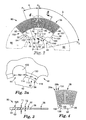
- Brush element 30 includes a generally circular center portion 32 having an inner edge 34 and an outer edge 36. A plurality of bristles 38 extend outwardly from outer edge 36. An interlock arrangement 42 is located at the inner edge 34. Interlock arrangement 42 is configured to interlock molded brush element 30 with an adjacent brush element.
- Brush element can be made having unitary center portion 32, and can also be made from two or more brush segments 80, 82, 84, 86. Adjacent brush segments, (e.g., 80, 82) are held together by an attachment arrangement (e.g., 102 in Figure 2 ).
- Brush element 30 or brush segment 80 can be made from a moldable polymeric material, several examples of which will be described hereinafter. Alternatively, each brush element or segment could be cast or made by other techniques known in the art.
- the material of the brush element 30 or segment 80 can also include abrasive particles. The particles can be on the bristle 38 surface or distributed throughout the bristle 38.
- brush element 30 is molded, such that bristles 38 and center portion 32 are continuous with one another.
- Interlock arrangement 42 is also operable as a mold gate interface, configured to improve mold material flow (as will be described hereinafter) from the inner edge 34 to the outer edge 36 during molding of brush element 30.
- interlock arrangement 42 includes an engaging member (e.g., 60) and a receiving area (e.g., 44) located at or near the inner edge 34.
- Interlock arrangement 42 engages a complementary interlock arrangement on adjacent brush element or elements to keep the brush elements from rotating relative to one another when the brush elements are stacked in a brush assembly.
- brush element 30 includes a plurality of receiving areas 44, 46, 48, 50, 52, 54, 56, 58 extending from the inner edge 34 into the center portion 32.
- One or more receiving areas form part of the interlock arrangements 42.
- Brush element 30 further includes a plurality of engaging members 60, 62, 64, 66, 68, 70, 72, 74 positioned along the inner edge 34.
- each engaging member is positioned along the inner edge 34 between two receiving areas.
- Interlock arrangement 42 includes at least one receiving area (e.g., receiving area 44) and at least one engaging member (e.g., engaging member 60).
- the brush element can also include an array of raised portions or members 85, for example, bosses, to assist in alignment of adjacent brush elements.
- Each raised portion 85 would have a corresponding receiving cavity (not shown) on the surface opposite the surface having the raised portions 85.
- Each raised portion 85 would be received into a respective receiving cavity of an adjacent element. Engagement of each raised portion 85 into its respective receiving cavity would assist in alignment of adjacent brush elements in creating bristle patterns (as described hereinafter) and also cooperate with the interlock arrangement to prevent relative rotation of adjacent brush elements.
- the raised portions 85 are spaced radially around each brush element with the same spacing interval as the interlock arrangement. It is also possible to use the raised portions and receiving cavities on adjacent brush element, without an interlock arrangement, to keep the adjacent elements from rotating relative to one another.
- Brush element 30 can be made up of a plurality of brush segments 80, 82, 84, 86. Each molded brush segment 80, 82, 84, 86 can include bristles 38 and center portion 32 that are continuous with one another.
- FIG 2 an exemplary embodiment of brush segment 80 of a brush element is shown. Brush segment 80 is similar to brush segment 82, brush segment 84 and brush segment 86 (as shown in Figure 1 ). Desirably, the brush segments in an element are congruent.
- Brush segment 80 includes a generally planar segment center portion 92 ( Figure 3 ). Center portion 92 extends in a generally arcuate shape between first and second side edges 94, 96. Bristles 38 extend radially outward from outer edge 36 of segment center portion 92. Interlock arrangement 42 is located at the inner edge 34 of segment center portion 92.
- Adjacent brush segments are held together by a cooperating attachment arrangement 100, 101.
- Brush segments 80, 86 are held together by a first attachment arrangement 100 near side edge 94 of center portion 32.
- Brush segments 80, 82 are held together by a second attachment arrangement 101 near side edge 96 of center portion 32.
- Individual brush segments are attached to adjacent brush segments to form a brush element.
- brush segments 80, 82, 84, 86 are attached to adjacent elements to form brush element 30.
- An additional way for holding adjacent segments can also be added along with the attachment arrangement, for example, welding the seam between segments or spot gluing.
- attachment mechanisms 100,101 are configured to operably interlock brush segment 80 with adjacent brush segments 82, 86.
- Attachment arrangement 100 holding brush segments 80, 86 together includes a first attachment member 102 received into a first holding area 103.
- Attachment arrangement 101 holding brush segments 80, 82 together includes a second attachment member 104 received into a second holding area 105.
- One of skill in the art will recognize that various suitable attachment arrangements can be used to hold together multiple adjacent brush segments to form a brush element.
- two or more brush elements can be formed into a brush assembly 200.
- Brush assembly 200 is typically mounted on a rotating member (not shown) that rotates the brush assembly, which then engages a substrate or work surface to remove material or otherwise modify from the substrate or work surface.
- a hub assembly (not shown) of a rotary tool can also be operably coupled the interlock arrangement of the brush element, thus eliminating or reducing the need for a component to interlock a brush assembly with the rotary tool.
- the brush elements of the present disclosure include an interlock arrangement to eliminate relative rotation between adjacent brush elements.
- adjacent brush elements are kept from rotating relative to one another by an interlock arrangement 42.
- Each adjacent brush element includes a complementary interlock arrangement (e.g., includes at least one receiving area, such as receiving area 44, and one engaging member, such as receiving member 62) extending from the inner edge 34 into the segment center portion 32.
- receiving area 44 is a regular geometrical shape, being partially circularly-shaped but can vary to any suitable shape. Other suitable shapes for receiving area 44 will become apparent to one skilled in the art after reading the present application.
- Brush element 30 ( Figure 1 ) includes multiple receiving areas 44, 46, 48, 50, 52, 54, 56, 58 spaced about inner edge 34. Each receiving area 44, 46, 48, 50, 52, 54, 56, 58 receives and holds its corresponding engagement member 60, 62, 64, 66, 68 70, 72, 74. When multiple brush segments are used to form a brush element, a receiving area can be formed between two adjacent segments, such as receiving area 56. Receiving area 56 is formed between and extends into adjacent disk segments 80, 86. similarly, receiving area 46 extends into and is formed between adjacent disk segments 80, 82.
- Interlock arrangement 42 includes an engaging member 62 positioned along the inner edge 34.
- Engaging member 62 is located between receiving area 44 and receiving area 46.
- Engaging member 62 includes an inner edge 112, a first corner 114 and a second corner 116.
- first corner 114 and second corner 116 are generally right-angled corners, but can be other shapes, for example, a corner having a radius.
- Engaging member 62 has a first width (W1) and receiving area 44 has a second width (W2) along the inner edge 34.
- W1 and W2 are approximately equal in width, though one skilled in the art will recognize other suitable arrangements can be used.
- brush element 30 includes eight regularly spaced interlock arrangements 42 with each receiving area and engaging member being of approximately equal width.
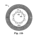
- Brush assembly 200 includes two adjacent brush elements 30a, . 30b.
- Brush elements 30a, 30b are oriented such that interlock arrangement 42a of brush 30a cooperates with interlock arrangement 42b of brush element 30b to restraint relative rotation between the brush elements 30a, 30b.
- Engagement member 60b of brush element 30b is received into and held by receiving area 58a of brush element 30a.
- Engagement member 60a of brush element 30a is received into and held by receiving area 44b of brush element 30b.
- an interlock arrangement on each brush element will cooperate with its corresponding interlock arrangement on the adjacent brush element to engage and keep the brush elements from rotating relative to one another.
- Adjacent brush elements (for example 30a and 30b) element can further be secured together, using, for example, adhesives, fasteners, or other suitable means (known to those skilled in the art). In this manner, any number of brush elements 30 may be assembled together to provide a brush assembly 200 of a desired width.
- Edge member 62 includes increased thickness portion 128 located at the inner edge 34.
- Increased thickness portion 128 has an increased thickness T1 relative to a thickness T2 of center portion 32 at outer edge 36. It is desirable that the engagement member 62 is of sufficient strength to resist any shear forces generated between adjacent brush elements. Desirably, the increased thickness portion 128 is up to 50% more than the thickness of element center portion 92 near outer edge 36, though it can be more, depending on the particular interlock arrangements.
- Increased thickness portion 128 of edge member 62 extends into a corresponding receiving area of a second brush element and operates to interlock the brush element with the adjacent brush element when positioned adjacent the second brush element.
- Each corresponding interlock arrangement engages to interlock adj acent brush elements at each increased thickness portion 128 to restrain relative circumferential movement between brush elements.
- bristles 38 of the brush segment 80 are integral with segment center portion 92. Bristles 38 extend radially outward from outer edge 36.
- bristles 38 include a first bristle row 38a spaced circumferentially about outer edge 36, and extending generally co-planar with surface 130 of segment center portion 92.
- Bristles 38 further include a second bristle row 38b, offset from first bristle row 38a.
- a second bristle row 38b extends radially outward from outer edge 36 and is spaced between the bristles located in bristle row 38a.
- brush segment 82 may include a single row of bristles 38, or more than two rows of bristles 38.
- Each bristle 38 includes a bristle root 132 and a bristle tip 134.
- Each bristle 38 extends from outer edge 36 at the bristle root.
- the area between adjacent bristle roots is generally rounded or filleted, indicated at 136. The generally rounded bristle root area provides increased strength at the location where each bristle 38 extends from outer edge 36 of segment center portion 92.
- Bristle 38 has a substantially rectangular cross-section, having a first square edge 142, a second square edge 144, a substantially rounded edge 146 and a substantially rounded edge 148.
- Bristles 38 may have other cross-sectional area shapes, including circular, star, half moon, quarter moon, oval, rectangular, square, triangular, diamond, or other polygonal shape or a combination of shapes.
- Figure 6 shows a bristle having a circular 700 cross-section
- Figure 7 shows a bristle having a cross-section including a semi-circular portion 703 and square portion 704
- Figure 8 shows a bristle having a square 701 cross-section.
- Bristles can also have a constant cross-section along the length of bristle 38, but can also include a non-constant or variable cross-section along the length of the bristle.
- Bristles 38 may be tapered such that the cross-sectional area of the bristle decreases in the direction away from root 132 toward tip 134.
- Tapered bristles 38 can have any cross-section, such as those indicated above.
- Bristles 38 are subjected to bending stresses as brush segment 92 is rotated against a work piece, illustrated in Figure 9 . These bending stresses are highest at the root 132 of bristles 38 (at outer edge 36).
- a tapered bristle generally resists bending stresses more than a bristle of constant cross-sectional area.
- Bristles 38 can have a taper along the entire length, or can have a tapered portion adjacent the root 132 and a constant cross-sectional area for the remainder of the bristle 38. The taper can be of any suitable angle.
- brush segment 80 can include a fillet radius at the transition between root 132 of bristle 38 and outer edge 36 of segment center portion 92. The particular bristle design is within the knowledge of one skilled in the art.
- Bristles 38 have an aspect ratio defined as the length of bristle 38 measured from outer root 132 to tip 134, divided by the width of the bristle.
- the width is defined as the average width along the length for purposes of determining the aspect ratio.
- the width is taken as the longest width in a given plane, such as the comer-to-comer diagonal of a square cross section.
- the aspect ratio of bristles 38 is desirably at least two, but can be smaller (in some embodiments, about five to one-hundred, or, for example, from about 50 to 75).
- the size of bristles 38 can be selected for the particular application of brush segment 80 and brush element 30.
- the width of bristles 38 can be the same as or different from the thickness of center portion 92. In one exemplary embodiment, all of the bristles 38 have the same dimensions.
- bristles 38 on a brush element 30 comprising a plurality of brush segments 80, 82, 84, 86 may have different dimensions such as different lengths, widths, or cross-sectional areas.
- a brush segment may have groups of short bristles and groups of long bristles. Further, it is possible to arrange brush segments to form a brush element, each brush segment having bristles of different length. Further, it is possible to employ adjacent brush segments having different bristles.
- bristles 38 can be chosen for the particular application in brush segment 80 and brush element 30 is used. Bristles 38 are typically arranged uniformly spaced around the perimeter or outer edge 36 of center portion 32. Alternatively, bristles 38 can be arranged in groups with spaces between the groups, and can also be oriented in the plane of center portion 32 other than radially outward, that is, at a non-zero angle relative to the radius of center portion 32. Accordingly, brush segment 80 may have a portion of outer edge 36 that does not include any bristles 38. The bristles may be present over only a portion of outer edge 36 of center portion 32. Bristles 38 may or may not abut adjacent bristles as desired.
- the material, length, and configuration of the bristles can be chosen such that bristles 38 are sufficiently flexible to aid in refining uneven or irregular work pieces.
- the bristles 38 are capable,of bending at least 25 degrees, (in some embodiments, at least 45 degrees, at least 90 degrees, or even about 180 degrees), without damage or substantial permanent deformation to the bristles.
- bristles 38 It is possible to reinforce the bristles 38 with a suitable structure. For example, it is possible to place a reinforcing fiber or wire in the bristle mold cavities, and inject the moldable polymer around the reinforcing wire, resulting in a bristle 38 having a reinforcing wire or fiber embedded within it.
- FIGs 10-12 illustrate exemplary embodiments of bristles 38 of a brush element in varying orientations relative to center portion 32.
- bristles 38 extend substantially radially outward from outer edge 36 of center portion 32.
- bristles 38 extend outward, at an angle ⁇ relative to outer edge 36 of center portion 32.
- bristles 38 are curved, extending radially outward from outer edge 36 of center portion 32.
- Other suitable bristle configurations for use with a brush element according to the present disclosure will become apparent to one skilled in the art after reading the present application.
- Figures 13a-13b illustrate one exemplary embodiment of positioning brush element 30a and brush element 30b together to form brush assembly 200.
- Figure 13a illustrates brush element 30a
- brush element 30a includes a first major surface 202a and a second major surface 202b (not shown).
- Figure 13b illustrates brush element 30b.
- Brush element 30b includes a first major surface 204a and a second major surface 204b (not shown).
- Figure 13c illustrates one embodiment of brush assembly 200 of a brush element comprising brush element 30a and brush element 30b.
- brush element 30b edge members e.g., edge member 60b
- are positioned within the receiving areas of brush element 30a e.g., edge member 60b is positioned within receiving area 44a).
- Figure 13d illustrates one exemplary embodiment of positioning brush element 30a and brush element 30b together to form brush assembly 200.
- Figure 13a illustrates brush element 30a
- brush element 30a includes a first major surface 202a and a second major surface 202b (
- First major surface 204a of brush element 30b is positioned against second major surface 202b of brush element 30a.
- Brush element 30a and brush element 30b are secured together, (e.g., using an adhesive).
- the positioning of brush element 30b edge members within the receiving areas of brush element 30a (or interlocking) eliminates movement (e.g., circumferential movement) between brush element 30a and brush element 30b, indicated by directional arrow 212.
- Bristles on the segment 80 are arranged so that there are two rows of alternating bristles.
- each row has one-hundred eight bristles when four brush segments are formed into a brush element, so that each brush element has two-hundred sixteen bristles regularly spaced around the circumference of the brush element.
- bristle patterns are possible that allow a single segment to form multiple bristle patterns or arrangements. Differing bristle patterns can provide differing finishing characteristics on a work piece or work surface. Additionally, differing bristle patterns may provide differing effects on a work surface or substrate.
- FIG 14 a partial diagram illustrating a first exemplary embodiment of an alternating bristle pattern 220 of a brush element is shown.
- Alternating bristle pattern 220 is achieved by positioning brush element 30b first major surface 204a against the brush element 30a second major surface 202b.
- the first bristle pattern is achieved by first placing two adjacent brush elements such that they are in-line with respect to their respective interlock arrangements. For example, referring to Figures 1 , 2 , and 13 , a second brush element 30a would be placed on a first brush element 30b so that the their respective engagement members 44b, 60b were coincidentally aligned.
- Bristle pattern 220 is created by rotating the first brush element 30b 22.5 degrees in a clockwise direction to engage engaging member 60b with receiving area 58a. The same pattern could also be achieved by rotating the first brush element 30b 67.5 (angle ⁇ ) degrees in a counter-clockwise direction. Bristles of the first brush element 30b are interleaved and over lap with bristles of the second brush element 30a in a plane taken radially between the center portions of each brush element.
- second bristle pattern 222 is shown. From the same starting point, second bristle pattern 222 is achieved by rotating the first brush element 30b 22.5 degrees in a counter-clockwise direction or 67.5 degrees in a clockwise direction from the alignment used to make the first bristle pattern 220.
- bristles of the first brush element 30b are interleaved and over lap with bristles of the second brush element 30a in a plane taken radially between the center portions of each brush element, but have a bias or relative orientation offset from the first pattern by about 90 degrees (i.e., line a-a, taken along the long axis of the first pattern 220a is about 90 degrees offset from line b-b, taken along the long axis of pattern 220b).
- Third bristle pattern 224 is creating by beginning with the first and second brush elements 30a, 30b coincident, as was done to create the first pattern 220. Before any rotation of the adjacent elements is done, first brush element 30b is rotated or flipped about its radial centerline (line R2 in Figure 2 ). Bristle pattern 224 is created by rotating the flipped first brush element 30b 22.5 degrees in a clockwise direction to engage the interlock arrangement. The same pattern could also be achieved by rotating first brush element 30b 67.5 degrees in a counter-clockwise direction.
- Bristles of the first brush element 30b are in-line with bristles of the second brush element 30a, as viewed along the center axis (through point P in Figure 2 ) of each element.
- this bristle pattern 224 the distance between alternating pairs of adjacent bristles is varied.
- a second inline pattern 226 is created by further rotating first brush element 30b 22.5 degrees in a counter-clockwise direction or 67.5 in a clockwise direction.
- the distance between alternating pairs of adjacent bristles is generally constant.
- the brush elements can include the raised portions and receiving cavities for assisting alignment and preventing relative rotation between elements (as previously described).
- a brush assembly can be made to include one or more of the patterns described.
- multiple patterns can be used in a single brush assembly.
- Other repeating bristle patterns can be made by creating symmetry between the interlock arrangement spacing and the bristle pattern on an individual brush element.
- the brush element and brush segments of the present disclosure can be made using various techniques known in the art, for example, injection molding, stamping, die cutting, sterolithography, or casting.
- injection molding typically, a moldable polymeric material, for example, thermoplastic polymers, thermosetting polymers, or thermoplastic elastomers, is used.
- Suitable materials for making injection molded abrasive brushes are known to one of skill in the art and their selection will depend on the application for which a brush segment or brush assembly will be used.
- One particular material that can be used in the brush segments and brush elements is a commercially available segmented polyester, including those marketed under the trade designations "HYTREL 4056", “HYTREL 5526", “HYTREL 5556”, “HYTREL 6356", “HYTREL 7246", and “HYTREL 8238” by E.I.Du Pont de Nemours and Company, Inc., Wilmington, DE.
- a similar family of thermoplastic polyesters is marketed under the trade designation "RITEFLEX” by Hoechst Celanese Corporation. Examples of suitable thermoplastic elastomers are described, for example, in U.S. Pat. No. 5,42,595 (Pihl et al. ).
- the brush elements and brush segments can also include abrasive particles.
- the abrasive particles can be on the surface of the abrading surface or member (e.g., bristles), dispersed throughout, or a combination thereof. Including abrasive particles throughout the bristles will allow the abrasive qualities of the bristles to remain relatively constant during use, even when the bristles wear and are reduced in size by use.
- Abrasive particles are known to those skilled in the art and the selection and incorporation of abrasive particles in the brush elements and segments will depend on a variety of factors, including the nature of the work surface and other operating conditions. The selection of a particular abrasive particle or particles is within the knowledge of one skilled in the art.
- abrasive particles include fused aluminum oxide, heat treated fused aluminum oxide, ceramic aluminum oxide, heat treated aluminum oxide, silicon carbide, titanium diboride, alumina zirconia, diamond, boron carbide, ceria, aluminum silicates, cubic boron nitride, garnet, silica, and combinations thereof.
- Fused aluminum oxides are commercially available, for example, from Exolon ESK Company, Tonawanda, NY, and Washington Mills Electro Minerals Corp., North Grafton, MA.
- Suitable ceramic aluminum oxide abrasive particles include those described in U.S. Pat. Nos. 4,314,827 (Leitheiser et al.
- Suitable alpha alumina-based ceramic abrasive particles comprising alpha alumina and rare earth oxide include those marketed under the designation "CUBITRON 321" by The 3M Company, St. Paul, MN.
- the abrasive particle can be any particulate material (inorganic or organic) that when combined with the binder results in a brush element that can refine a workpiece surface.
- the selection of the abrasive material will depend in part on the intended application. For example, for stripping paints from a vehicle, it is sometimes desirable to omit abrasive particles from the brush element. It is sometimes desirable to use a relatively soft abrasive particle when stripping paints so as not to damage the surface underneath the paint.
- the brush element of the present disclosure may include two or more types and/or sizes of abrasive particles in those embodiments that include the optional abrasive particles.
- abrasive particle also encompasses single abrasive particles that are bonded together to form an abrasive agglomerate.
- the addition of the coating improves the abrading and/or processing characteristics of the abrasive particle. Examples of abrasive agglomerates are found in, for example, U.S. Pat. No. 5,011,508 (Wald et al. ).
- Organic abrasive particles suitable for use with the brush element of the present disclosure include those formed from a thermoplastic polymer and/or a thermosetting polymer.
- Organic abrasive particles useful in the present disclosure may be individual particles or agglomerates of individual particles. The agglomerates may comprise a plurality of the organic abrasive particles bonded together by a binder to form a shaped mass.
- the polymeric material used to make brush elements and brush segments of the present disclosure may further include a grinding aid.
- a grinding aid is a particulate material that the addition of which has a significant effect on the chemical and physical processes of abrading, resulting in improved performance.
- chemical groups of grinding aids include waxes, organic halide compounds, halide salts and metals and their alloys.
- the organic halide compounds will typically break down during abrading and release a halogen acid or a gaseous halide compound. Examples of such materials include chlorinated waxes like tetrachloronaphthalene, pentachloronaphthalene, and polyvinyl chloride.
- halide salts include sodium chloride, potassium cryolite, sodium cryolite, ammonium cryolite, potassium tetrafluoroborate, sodium tetrafluoroborate, silicon fluorides, potassium chloride, magnesium chloride.
- metals include, tin, lead, bismuth, cobalt, antimony, cadmium, iron, and titanium.
- Other miscellaneous grinding aids include sulfur, organic sulfur compounds, graphite and metallic sulfides.
- the brush element or brush segments of the present disclosure can be made, for example by injection molding. Injection molding techniques are known in the art.
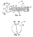
- An exemplary injection molding apparatus 230 for making brush segment of a brush element according to the method of the present disclosure is illustrated in Figure 18 .
- a mixture of pellets comprising moldable polymer and, optionally, abrasive particles is placed in a hopper 242.
- the hopper 242 feeds the mixture into a first or rear side 250 of a screw injector 244 generally comprising a screw 246 within a barrel 248.
- the opposite side, or front side 252 of screw injector 244 includes nozzle 254 for passing the softened mixture into mold 256a, 256b.
- Barrel 248 of injector 244 is heated to melt the mixture, and rotating screw 66 propels the mixture in the direction of nozzle 254. Screw 246 is then moved linearly frontward in direction B to impart the "shot" of the softened mixture into mold 256a, 256b at the desired pressure. A gap is generally maintained between the forward end of the screw and the nozzle to provide a "cushion" area of softened material that is not injected into the mold.
- the mold 256a, 256b contains cavities that are the inverse of the desired brush segment configuration.
- the mold design takes into account the brush segment configuration including the size and configuration of center portion 32, bristles 38, and optional attachment means such as holes, roots, keyways, or a threaded stud.
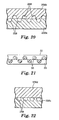
- mold portion 256a includes cavities 258 for forming bristles.
- the exemplary mold embodiment illustrated in Figure 20 is configured to mold a double row of staggered bristles. Such a bristle arrangement is illustrated in Figure 21 .
- mold portions 256c and 256d illustrated in Figure 22 can be used to form a single row of bristles 18, or a combination of the desirable single row configuration.
- pellets can be prepared, for example, as follows. Moldable polymer is heated above its melting point and optional abrasive particles, if desired, can then be mixed in. The resulting mixture is then formed into continuous strands and the strands are cooled to solidify the moldable polymer for pelletizing on suitable equipment as is known in the art. Likewise, lubricants and/or other additives to the polymeric material can be included in the formation of the pellets. The pellets comprising moldable polymer, abrasive particles, and any desired lubricant or other additive are then placed into hopper 242 to be fed into screw extruder 244 as described above.
- moldable polymer is first heated to in a range from 70°C. to 120°C., (in some embodiments, in a range from 80°C to 100°C.) for drying, and is placed in hopper 242 to be gravity fed into the screw feed zone.
- the barrel temperature of the screw injector is desirably from about 200°C. to 250°C., and more desirably from about 220°C. to 245°C.
- the temperature of the mold is desirably from about 50°C to 150°C., and more desirably from about 100°C. to 140°C.
- the cycle time (the time from introducing the mixture into the screw extruder to opening the mold to remove the molded brush segment) will desirably range between 0.5 to 180 seconds, more desirably from about 5 to 60 seconds.
- the injection pressure will desirably range from about 690 to 6,900 kPa (100 to 1000 psi), more desirably from about 2070 to 4830 kPa (300 to 700 psi).
- the choice of the particular operating conditions for injection molding is within the knowledge of one skilled in the art, and can vary outside of the example ranges given, depending on the particular application.
- the injection mold cycle will depend upon the material composition and the brush segment configuration.
- the moldable polymer and abrasive particles are generally uniformly dispersed throughout brush segment 80.
- bristles may contain abrasive particles, but center portion does not.
- the second insertion will contain moldable polymer (which may be the same or different from the moldable polymer of the first insertion) without abrasive particles to primarily fill the center portion and root portions of the mold.
- center portion and bristles may contain abrasive particles, while root may not contain abrasive particles.
- the first insertion will contain a mixture of moldable polymer and abrasive particles to fill the bristle and center portion portions of the mold.
- the second insertion will contain only a moldable polymer (which may be the same or different from the moldable polymer of the first insertion) to primarily fill the attachment means portion of the mold.
- Interlock arrangement 42 operates as a mold gate interface located at inner edge 34, configured to improve mold flow from the inner edge 34 to outer edge 36 during molding of the brush segments 80. Mold flow lines are illustrated at 300.
- Mold flow lines are illustrated at 300.
- Edge members 60, 62 interlock directly with a mold gate.
- Receiving areas 58, 56, and 46 operate to direct mold flow; resulting in more uniform mold flow to outer edge 36.
- the increased thickness portion 128 immediately adjacent a mold gate results in further uniformity of mold flow to outer edge 36.
- Molded brush segment 80 requires less material for molding due to the presence of receiving areas 5 8, 44 and 46.
- Molded brush segment 80a additionally include openings 310, 312, 314. Openings 310, 312,314 provide further optimization of mold flow during molding of molded brush segment 80. Openings 310, 312, 314 provide for further directing of mold flow, indicated by flow vectors 320.
- FIG. 25 an example embodiment of a mold 350 for making brush segments of a brush element of the present disclosure is shown.
- Two different brush segments 360, 370 are made on mold 350.
- Brush segment 360 includes curved bristles 352.
- Brush segment 370 includes straight bristles.
- each brush segment has an 8-inch (203.2 mm) diameter, although other sizes can be made according to the present disclosure.
- Each engagement member 354, 374 interfaces with a respective mold gate 353, 373. By locating the mold gate at the increased thickness portion of the engaging members 354, 374, mold flow into the mold is improved, as previously described. While the example embodiment mold shown makes brush segments, the mold could also be designed to make other combinations, for example, a single brush element, or more or less similar or different brush segments.
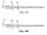
- FIGS 26a-b shown are cross-sectional views of example embodiments for brush elements for an 8-inch (203.2 mm) diameter brush, similar to the view of Figure 3 .
- a brush element having curved bristles including a center portion thickness TC1 of about 0.050 inches (1.27 mm).
- Increased thickness portion TP1 is about 0.094 inches (2.39 mm) with an increased thickness TI1 of about 0.022 inches (0.559 mm) on each side of the engaging member.
- the brush element of Figure 26a could be made thicker, including a center portion thickness TC1 of about 0.062 inches (1.57 mm), with the increased thickness portion TP1 (at the interlock arrangement engaging member) about 0.120 inches (3.05 mm) and with an increased thickness TI1 of about 0.016 inches (0.406 mm) on each side of the engaging member.
- a brush element having straight bristles including a center portion thickness TC2 of about 0.050 inches (1.27 mm).
- Increased thickness portionTP2 (at the interlock arrangement engaging member) is about 0.094 inches (2.39 mm) with an increased thickness TI2 of about 0.022 inches (0.559 mm) on each side of the engaging member.
- the brush element of Figure 26b could be made thicker, including a center portion thickness TC2 of about 0.062 inches (1.57 mm).
- Increased thickness portion TP2 (at the interlock arrangement engaging member) is about 0.120 (3.05 mm) inches with an increased thickness TI2 of about 0.016 inches (0.406 mm) on each side of the engaging member.
- the brush elements and segments of the present disclosure can be made with a variety of combinations of parameters, for example, bristle size and shape, disc radius, center portion thickness, and the forgoing examples are for illustrative purposes.
- brush elements, brush segments, and brush assemblies can be used to refine a surface.
- a method of refining a surface includes one or more of the following: removing a portion of a workpiece surface; imparting a surface finish to a workpiece; cleaning a workpiece surface, including removing paint or other coatings, gasket material, corrosion, or other foreign material; or some combination of the foregoing.
- brush assembly 200 comprises a plurality of brush elements 30 fastened by an attachment means to a shaft and a suitable drive means.
- the elements 30 can be mounted to a suitable rotary drive means, such as commercially available right angle grinders.
- Surface refining can be dry or wet, as with water, lubricant, rust inhibitor, or other suitable liquids, as is well known in the art.
- the brush assembly 200 can be rotated at any suitable speed, desirably in the range up to 15,000 RPMs or as low as 100 RPMs, although higher or lower speeds can be used as desired.
- Surface refinement can be performed with any suitable force on the brush assembly or segment, typically up to about 100 kg and as low as 0.5 kg, though more or less force may be used.
- the bristles 38 are sufficiently flexible and supple that, under many refining operations, contact of the bristle against the workpiece is along a substantial length of the side of the bristle, not merely a small portion of the bristle immediately adjacent the tip 134.
- the molded brush segment or brush assembly can be used to remove a foreign material, for example paint, dirt, debris, oil, oxide coating, rust, adhesive, gasket material and the like, from a workpiece surface without removing a significant amount of material from the workpiece itself.
- the present disclosure has now been described with reference to several embodiments thereof.
- the foregoing detailed description and examples have been given for clarity of understanding only. No unnecessary limitations are to be understood therefrom.
- fluid such as coolants, lubricants, and cleaning fluids to the workpiece during operation as is known in the art, such as by openings through the backing or bristles.
- the scope of the present disclosure should not be limited to the exact details and structures described herein, but rather by the structures described by the language of the claims, and the equivalents of those structures.
Landscapes
- Chemical & Material Sciences (AREA)
- Engineering & Computer Science (AREA)
- Materials Engineering (AREA)
- Polishing Bodies And Polishing Tools (AREA)
- Brushes (AREA)
- Motor Or Generator Current Collectors (AREA)
- Sealing Devices (AREA)
Applications Claiming Priority (3)
| Application Number | Priority Date | Filing Date | Title |
|---|---|---|---|
| US10/389,788 US7121937B2 (en) | 2003-03-17 | 2003-03-17 | Abrasive brush elements and segments |
| US389788 | 2003-03-17 | ||
| PCT/US2004/002108 WO2004082429A2 (en) | 2003-03-17 | 2004-01-26 | Abrasive brush elements |
Publications (2)
| Publication Number | Publication Date |
|---|---|
| EP1603427A2 EP1603427A2 (en) | 2005-12-14 |
| EP1603427B1 true EP1603427B1 (en) | 2008-10-29 |
Family
ID=32987434
Family Applications (1)
| Application Number | Title | Priority Date | Filing Date |
|---|---|---|---|
| EP04705292A Expired - Lifetime EP1603427B1 (en) | 2003-03-17 | 2004-01-26 | Abrasive brush elements and segments |
Country Status (11)
| Country | Link |
|---|---|
| US (1) | US7121937B2 (enExample) |
| EP (1) | EP1603427B1 (enExample) |
| JP (1) | JP4693770B2 (enExample) |
| KR (1) | KR101107857B1 (enExample) |
| CN (1) | CN100446694C (enExample) |
| AT (1) | ATE412351T1 (enExample) |
| AU (1) | AU2004222415A1 (enExample) |
| BR (1) | BRPI0408416A (enExample) |
| CA (1) | CA2519428A1 (enExample) |
| DE (1) | DE602004017433D1 (enExample) |
| WO (1) | WO2004082429A2 (enExample) |
Families Citing this family (25)
| Publication number | Priority date | Publication date | Assignee | Title |
|---|---|---|---|---|
| PL1524078T3 (pl) * | 2003-10-14 | 2015-06-30 | Tenax Spa | Układ roboczy wykorzystujący narzędzie szczotkujące |
| US7081043B2 (en) * | 2004-01-14 | 2006-07-25 | 3M Innovative Properties Company | Molded abrasive brush and methods of using for manufacture of printed circuit boards |
| US8105134B2 (en) * | 2005-01-25 | 2012-01-31 | Epoxi Tech, Inc. | Low pressure polishing method and apparatus |
| US20050282474A1 (en) * | 2004-06-17 | 2005-12-22 | Wagner Spray Tech Corporation | Powered paint preparation tool, kit and method |
| JP2008096948A (ja) * | 2006-09-12 | 2008-04-24 | Ricoh Co Ltd | 画像形成装置、プロセスカートリッジ |
| GB2444774A (en) * | 2006-12-13 | 2008-06-18 | Brush Technology Ltd | Rotary Brush |
| JP5306619B2 (ja) * | 2007-09-06 | 2013-10-02 | スリーエム イノベイティブ プロパティズ カンパニー | 線形研磨ブラシ部材、線形研磨ブラシ部材の製造方法、及び研磨ブラシ |
| US20110126961A1 (en) | 2009-12-02 | 2011-06-02 | Bridgestone Bandag, Llc | Passive buffer brush air cooling |
| EP2616219A4 (en) * | 2010-09-15 | 2015-05-27 | Saint Gobain Abrasives Inc | IMPRESENTED FRICTION BRUSH |
| CN102049396A (zh) * | 2010-12-16 | 2011-05-11 | 中国人民解放军91872部队 | 清洁头装置 |
| DE102011114916B4 (de) * | 2011-10-06 | 2019-12-19 | Eve Ernst Vetter Gmbh | Radialbürste |
| DE102011122106A1 (de) * | 2011-12-22 | 2013-06-27 | Carl Freudenberg Kg | Besenblock mit Borstenstruktur |
| US20130331003A1 (en) * | 2012-05-17 | 2013-12-12 | Nils Eric Simonsen | Systems and methods for machine polishing a pattern onto metal using abrasive disks |
| ITBO20120571A1 (it) * | 2012-10-19 | 2014-04-20 | Daniele Trasforini | Metodo di realizzazione di una spazzola e spazzola cosi' ottenuta. |
| US9538835B2 (en) * | 2014-10-29 | 2017-01-10 | Herman Grewal | Bristle extruding toothbrush |
| CN105124916A (zh) * | 2015-08-26 | 2015-12-09 | 安徽振达刷业有限公司 | 一种清扫毛刷生产方法 |
| CN105231653A (zh) * | 2015-08-26 | 2016-01-13 | 安徽振达刷业有限公司 | 一种长时间不变形不掉毛的刷毛生产方法 |
| DE102016220766B4 (de) * | 2016-10-21 | 2018-08-23 | Boeck Gmbh | Werkzeug zum Bearbeiten eines Objektes |
| CH713380A2 (de) * | 2017-01-20 | 2018-07-31 | Vogel Josef | Werkzeug mit einer Vielzahl von flexiblen Bearbeitungsmitteln am Umfang eines um eine Werkzeugachse drehbaren Basiskörpers zur Bearbeitung von Oberflächen, Kantenbereichen und Konturen. |
| USD848691S1 (en) * | 2017-11-15 | 2019-05-14 | Steven M Antler | Bristles of a brush |
| JP7212457B2 (ja) * | 2018-04-27 | 2023-01-25 | 小林製薬株式会社 | 歯間清掃具 |
| USD899095S1 (en) * | 2019-12-30 | 2020-10-20 | Freeman Gormany | Powered toilet bowl brush |
| DE102022117629A1 (de) * | 2022-07-14 | 2024-01-25 | Eve Ernst Vetter Gmbh | Radialbürste für Schleif- oder Polierzwecke |
| CN115366015B (zh) * | 2022-09-20 | 2023-08-15 | 广东捷骏电子科技有限公司 | 陶瓷刷轮的制备方法 |
| US12161217B1 (en) * | 2024-05-10 | 2024-12-10 | Quick Quack Car Wash Holdings, LLC | Apparatus and method for a top wrap assembly |
Family Cites Families (67)
| Publication number | Priority date | Publication date | Assignee | Title |
|---|---|---|---|---|
| US3080657A (en) | 1963-03-12 | Lanski | ||
| GB223163A (en) | 1924-05-07 | 1924-10-16 | Laurits Henrik Nielsen | Improvements in and relating to rotary brushes |
| US2877481A (en) | 1955-01-05 | 1959-03-17 | Pittsburgh Plate Glass Co | Rotary brush sections |
| US2821729A (en) | 1955-02-16 | 1958-02-04 | Pittsburgh Plate Glass Co | Means for locking brush bristles in retaining structures |
| US3233272A (en) * | 1964-03-23 | 1966-02-08 | Pambello Samuel Michael | Rotary brush |
| JPS4212265Y1 (enExample) * | 1965-03-25 | 1967-07-11 | ||
| US3643281A (en) * | 1969-01-06 | 1972-02-22 | Mfg Brush Co The | Rotary brush |
| US3641611A (en) * | 1969-10-06 | 1972-02-15 | Manufactures Brush Co The | Brush construction |
| US3851350A (en) | 1973-08-06 | 1974-12-03 | Mfg Brush Co | Interlocking rotary brush construction |
| US4307479A (en) | 1979-10-19 | 1981-12-29 | Superior Brush Company | Angle tufted rotary brush assembly |
| US4422986A (en) | 1981-09-23 | 1983-12-27 | Cole William E | Method and apparatus for infection molding brushes |
| JPS59114018U (ja) * | 1983-01-21 | 1984-08-01 | 昭和工業株式会社 | 回転ブラシ |
| JPS6134926U (ja) * | 1984-08-07 | 1986-03-04 | 一雄 石川 | ロ−ルブラシ用デイスクブラシ |
| DE3444763A1 (de) * | 1984-12-07 | 1986-06-12 | Oskar Dilo Maschinenfabrik Kg, 6930 Eberbach | Anlage zum herstellen strukturierter textiler velournadelfilzbahnen |
| DE3711181A1 (de) | 1987-04-02 | 1988-10-13 | Jakob Reislaender Fabrik Tech | Tellerbesen, insbesondere rinnsteinbesen fuer strassenkehrmaschinen |
| US5045091A (en) | 1987-06-26 | 1991-09-03 | Minnesota Mining And Manufacturing Company | Method of making rotary brush with removable brush elements |
| US5928589A (en) | 1987-12-28 | 1999-07-27 | Teijin Limited | Processing for producing shaped wholly aromatic polyamide resin composition article and shaped article produced thereby |
| US4989166A (en) | 1988-07-12 | 1991-01-29 | Hitachi, Ltd. | Method for synthesizing analysis model and flow analysis system |
| JPH0620417Y2 (ja) * | 1990-05-18 | 1994-06-01 | 株式会社バーテック | ロールブラシ |
| US5632790A (en) | 1990-05-21 | 1997-05-27 | Wiand; Ronald C. | Injection molded abrasive article and process |
| ES2071703T3 (es) | 1990-06-28 | 1995-07-01 | Boucherie Nv G B | Maquina para fabricar cepillos. |
| US6069080A (en) | 1992-08-19 | 2000-05-30 | Rodel Holdings, Inc. | Fixed abrasive polishing system for the manufacture of semiconductor devices, memory disks and the like |
| DE4306965C1 (de) | 1992-10-19 | 1994-04-28 | Starck H C Gmbh Co Kg | Verfahren zur Herstellung von Schleifkörnern |
| US5400458A (en) | 1993-03-31 | 1995-03-28 | Minnesota Mining And Manufacturing Company | Brush segment for industrial brushes |
| US6083445A (en) | 1993-07-13 | 2000-07-04 | Jason, Inc. | Method of making a plateau honing tool |
| US6129620A (en) | 1993-04-23 | 2000-10-10 | Jason Incorporated | Honing tool and method of making |
| US5367833A (en) | 1993-10-22 | 1994-11-29 | Extrude Hone Corporation | Unidirectional abrasive flow machining |
| JPH07204999A (ja) | 1994-01-07 | 1995-08-08 | Hotani:Kk | 金属ストリップ研磨方法 |
| US5438728A (en) | 1994-03-18 | 1995-08-08 | Minnesota Mining And Manufacturing Company | Rotary brush with segmented fiber sections |
| US5722106B1 (en) | 1995-02-01 | 2000-06-06 | Gillette Canada | Tooth polishing brush |
| NZ300877A (en) | 1995-02-16 | 1999-04-29 | Noblecrest Marketing Pty Ltd | Sweeping device comprising a head portion and a socket integrally formed on the upper surface of the head portion |
| CA2217983A1 (en) | 1995-04-28 | 1996-10-31 | Minnesota Mining And Manufacturing Company | Abrasive article having a bond system comprising a polysiloxane |
| US5679067A (en) | 1995-04-28 | 1997-10-21 | Minnesota Mining And Manufacturing Company | Molded abrasive brush |
| USD381139S (en) | 1995-04-28 | 1997-07-15 | Minnesota Mining And Manufacturing Company | Molded abrasive brush |
| FR2735336B1 (fr) | 1995-06-16 | 1997-08-22 | Dalmasso Christian | Brosse rotative modulaire obtenue par l'assemblage par emboitage decale de demi-anneaux garnis de poils |
| JP3226447B2 (ja) | 1995-09-08 | 2001-11-05 | 住友化学工業株式会社 | プレス成形又は射出プレス成形のシミュレーション方法 |
| USD378003S (en) | 1995-11-16 | 1997-02-11 | Minnesota Mining And Manufacturing Company | Molded radial brush |
| US6352471B1 (en) * | 1995-11-16 | 2002-03-05 | 3M Innovative Properties Company | Abrasive brush with filaments having plastic abrasive particles therein |
| US5903951A (en) * | 1995-11-16 | 1999-05-18 | Minnesota Mining And Manufacturing Company | Molded brush segment |
| USD378004S (en) | 1995-11-16 | 1997-02-11 | Minnesota Mining And Manufacturing Company | Radial brush segment |
| CN2260502Y (zh) * | 1996-09-10 | 1997-08-27 | 阎宝福 | 一种钢丝轮刷 |
| DE29617206U1 (de) | 1996-10-02 | 1996-12-05 | Osborn International GmbH, 35099 Burgwald | Rotationsbürste zur Oberflächenbehandlung von Werkstücken |
| DE29620104U1 (de) | 1996-11-19 | 1998-03-19 | Wesumat Fahrzeugwaschanlagen GmbH, 86156 Augsburg | Streifenförmiges Arbeitselement für Wasch-, Trocknungs- und Polierwalzen |
| US5964006A (en) | 1997-01-13 | 1999-10-12 | 3M Innovative Properties Company | Rotary surface treatment tool |
| US6012971A (en) | 1997-03-14 | 2000-01-11 | Edgecraft Corporation | Sharpening apparatus |
| DE29707909U1 (de) | 1997-05-02 | 1998-09-03 | Wesumat Fahrzeugwaschanlagen GmbH, 86156 Augsburg | Arbeitswalze, insbesondere Waschwalze für Fahrzeugwaschanlagen |
| US5983434A (en) | 1997-07-15 | 1999-11-16 | Minnesota Mining And Manufacturing Company | Rotary bristle tool with preferentially oriented bristles |
| US6095910A (en) | 1997-11-10 | 2000-08-01 | 3M Innovative Properties Company | Surface treatment article having a quick release fastener |
| US5938515A (en) | 1997-12-01 | 1999-08-17 | Lake Country Manufacturing, Inc. | Foam buffing pad of string-like construction |
| JPH11165266A (ja) | 1997-12-05 | 1999-06-22 | Toshiba Corp | 研磨パッド |
| DE19843583C2 (de) | 1998-09-23 | 2001-09-06 | Harald Vorbach | Ausgestaltung und Verfahren zur Herstellung von Waschelementen und deren Anordnung auf einer Walze |
| US6174600B1 (en) | 1998-11-05 | 2001-01-16 | Speciality Filaments, Inc. | Bristles employing particulates and brushes including same |
| JP3824041B2 (ja) | 1998-12-04 | 2006-09-20 | 株式会社三▲しゅう▼プレシジョン | 歯間清掃具及びその製造方法 |
| US6261167B1 (en) | 1998-12-15 | 2001-07-17 | Diamond Machining Technology, Inc. | Two-sided abrasive tool and method of assembling same |
| JP4493112B2 (ja) * | 1999-01-08 | 2010-06-30 | スリーエム カンパニー | 研磨ブラシ |
| US6179887B1 (en) * | 1999-02-17 | 2001-01-30 | 3M Innovative Properties Company | Method for making an abrasive article and abrasive articles thereof |
| USD427395S (en) | 1999-05-21 | 2000-06-27 | 3M Innovative Properties Company | Bristles of a brush |
| USD425269S (en) | 1999-05-21 | 2000-05-16 | 3M Innovative Properties Company | Bristles of a brush |
| USD424258S (en) | 1999-05-21 | 2000-05-02 | 3M Innovative Properties Company | Bristles of a brush |
| USD424765S (en) | 1999-05-21 | 2000-05-09 | 3M Innovative Properties Company | Center portion of a brush |
| US6261168B1 (en) | 1999-05-21 | 2001-07-17 | Lam Research Corporation | Chemical mechanical planarization or polishing pad with sections having varied groove patterns |
| CN2382286Y (zh) * | 1999-07-18 | 2000-06-14 | 段梦麟 | 一种钢丝辊刷 |
| US6406363B1 (en) | 1999-08-31 | 2002-06-18 | Lam Research Corporation | Unsupported chemical mechanical polishing belt |
| US6422932B1 (en) * | 1999-10-15 | 2002-07-23 | 3M Innovative Properties Company | Integrally molded brush and method for making the same |
| TW584591B (en) | 2000-06-08 | 2004-04-21 | Mirle Automation Corp | Method of setting parameters for injection molding machine |
| US6477729B1 (en) * | 2000-07-18 | 2002-11-12 | Tsafrir Ben-Ari | Toothbrush with longitudinal to lateral motion conversion |
| CN1371643A (zh) * | 2001-02-28 | 2002-10-02 | 林心正 | 具有高刚性磨粒的钢刷及其制造方法 |
-
2003
- 2003-03-17 US US10/389,788 patent/US7121937B2/en not_active Expired - Lifetime
-
2004
- 2004-01-26 BR BRPI0408416-0A patent/BRPI0408416A/pt not_active IP Right Cessation
- 2004-01-26 KR KR1020057017388A patent/KR101107857B1/ko not_active Expired - Fee Related
- 2004-01-26 CA CA002519428A patent/CA2519428A1/en not_active Abandoned
- 2004-01-26 DE DE602004017433T patent/DE602004017433D1/de not_active Expired - Lifetime
- 2004-01-26 CN CNB2004800074480A patent/CN100446694C/zh not_active Expired - Lifetime
- 2004-01-26 AT AT04705292T patent/ATE412351T1/de not_active IP Right Cessation
- 2004-01-26 JP JP2006508626A patent/JP4693770B2/ja not_active Expired - Fee Related
- 2004-01-26 AU AU2004222415A patent/AU2004222415A1/en not_active Abandoned
- 2004-01-26 EP EP04705292A patent/EP1603427B1/en not_active Expired - Lifetime
- 2004-01-26 WO PCT/US2004/002108 patent/WO2004082429A2/en not_active Ceased
Also Published As
| Publication number | Publication date |
|---|---|
| WO2004082429A3 (en) | 2005-01-06 |
| ATE412351T1 (de) | 2008-11-15 |
| BRPI0408416A (pt) | 2006-03-21 |
| US7121937B2 (en) | 2006-10-17 |
| CN1761417A (zh) | 2006-04-19 |
| AU2004222415A1 (en) | 2004-09-30 |
| CN100446694C (zh) | 2008-12-31 |
| KR20050110676A (ko) | 2005-11-23 |
| US20040185762A1 (en) | 2004-09-23 |
| JP4693770B2 (ja) | 2011-06-01 |
| CA2519428A1 (en) | 2004-09-30 |
| EP1603427A2 (en) | 2005-12-14 |
| JP2006520662A (ja) | 2006-09-14 |
| WO2004082429A2 (en) | 2004-09-30 |
| KR101107857B1 (ko) | 2012-01-31 |
| DE602004017433D1 (de) | 2008-12-11 |
Similar Documents
| Publication | Publication Date | Title |
|---|---|---|
| EP1603427B1 (en) | Abrasive brush elements and segments | |
| US5903951A (en) | Molded brush segment | |
| EP1106102B1 (en) | Abrasive brush and filaments | |
| US6261156B1 (en) | Molded abrasive brush | |
| US12377522B2 (en) | Elongate abrasive article with orientationally aligned formed abrasive particles | |
| KR20010021840A (ko) | 선택적으로 배향되는 강모를 갖는 회전 강모 공구 | |
| CN1906982B (zh) | 模制研磨刷和用于制造印刷电路板的方法 | |
| EP2150149B1 (en) | Abrasive filament and brush | |
| US20090191798A1 (en) | Integrally molded brush and the method of manufacture and its uses thereof | |
| US20250018534A1 (en) | Abrasive articles and systems | |
| EP1755828B1 (en) | Abrasive cleaning device | |
| US2079995A (en) | Abrasive tool | |
| JPH0783725B2 (ja) | シート状ブラシ材料及びブラシ構造物 | |
| JP7708673B2 (ja) | 切断粒子を備える非対称の歯を有する切削工具 | |
| CA2077568A1 (en) | Grinding tool | |
| TW201703687A (zh) | 刷子用毛材及刷輥 | |
| US3233271A (en) | Self-regulating composite brushing tool | |
| JP3317478B2 (ja) | ダイヤモンド切断砥石 | |
| WO2025149869A1 (en) | Surface conditioning article | |
| JPH1076470A (ja) | 研磨用砥石車 |
Legal Events
| Date | Code | Title | Description |
|---|---|---|---|
| PUAI | Public reference made under article 153(3) epc to a published international application that has entered the european phase |
Free format text: ORIGINAL CODE: 0009012 |
|
| 17P | Request for examination filed |
Effective date: 20050919 |
|
| AK | Designated contracting states |
Kind code of ref document: A2 Designated state(s): AT BE BG CH CY CZ DE DK EE ES FI FR GB GR HU IE IT LI LU MC NL PT RO SE SI SK TR |
|
| AX | Request for extension of the european patent |
Extension state: AL LT LV MK |
|
| DAX | Request for extension of the european patent (deleted) | ||
| 17Q | First examination report despatched |
Effective date: 20061201 |
|
| 17Q | First examination report despatched |
Effective date: 20061201 |
|
| GRAP | Despatch of communication of intention to grant a patent |
Free format text: ORIGINAL CODE: EPIDOSNIGR1 |
|
| GRAJ | Information related to disapproval of communication of intention to grant by the applicant or resumption of examination proceedings by the epo deleted |
Free format text: ORIGINAL CODE: EPIDOSDIGR1 |
|
| GRAP | Despatch of communication of intention to grant a patent |
Free format text: ORIGINAL CODE: EPIDOSNIGR1 |
|
| GRAS | Grant fee paid |
Free format text: ORIGINAL CODE: EPIDOSNIGR3 |
|
| GRAA | (expected) grant |
Free format text: ORIGINAL CODE: 0009210 |
|
| AK | Designated contracting states |
Kind code of ref document: B1 Designated state(s): AT BE BG CH CY CZ DE DK EE ES FI FR GB GR HU IE IT LI LU MC NL PT RO SE SI SK TR |
|
| REG | Reference to a national code |
Ref country code: GB Ref legal event code: FG4D |
|
| REG | Reference to a national code |
Ref country code: CH Ref legal event code: EP |
|
| REG | Reference to a national code |
Ref country code: IE Ref legal event code: FG4D |
|
| REF | Corresponds to: |
Ref document number: 602004017433 Country of ref document: DE Date of ref document: 20081211 Kind code of ref document: P |
|
| NLV1 | Nl: lapsed or annulled due to failure to fulfill the requirements of art. 29p and 29m of the patents act | ||
| PG25 | Lapsed in a contracting state [announced via postgrant information from national office to epo] |
Ref country code: BG Free format text: LAPSE BECAUSE OF FAILURE TO SUBMIT A TRANSLATION OF THE DESCRIPTION OR TO PAY THE FEE WITHIN THE PRESCRIBED TIME-LIMIT Effective date: 20090129 Ref country code: ES Free format text: LAPSE BECAUSE OF FAILURE TO SUBMIT A TRANSLATION OF THE DESCRIPTION OR TO PAY THE FEE WITHIN THE PRESCRIBED TIME-LIMIT Effective date: 20090209 Ref country code: AT Free format text: LAPSE BECAUSE OF FAILURE TO SUBMIT A TRANSLATION OF THE DESCRIPTION OR TO PAY THE FEE WITHIN THE PRESCRIBED TIME-LIMIT Effective date: 20081029 |
|
| PG25 | Lapsed in a contracting state [announced via postgrant information from national office to epo] |
Ref country code: NL Free format text: LAPSE BECAUSE OF FAILURE TO SUBMIT A TRANSLATION OF THE DESCRIPTION OR TO PAY THE FEE WITHIN THE PRESCRIBED TIME-LIMIT Effective date: 20081029 Ref country code: SI Free format text: LAPSE BECAUSE OF FAILURE TO SUBMIT A TRANSLATION OF THE DESCRIPTION OR TO PAY THE FEE WITHIN THE PRESCRIBED TIME-LIMIT Effective date: 20081029 Ref country code: PT Free format text: LAPSE BECAUSE OF FAILURE TO SUBMIT A TRANSLATION OF THE DESCRIPTION OR TO PAY THE FEE WITHIN THE PRESCRIBED TIME-LIMIT Effective date: 20090330 Ref country code: FI Free format text: LAPSE BECAUSE OF FAILURE TO SUBMIT A TRANSLATION OF THE DESCRIPTION OR TO PAY THE FEE WITHIN THE PRESCRIBED TIME-LIMIT Effective date: 20081029 |
|
| PG25 | Lapsed in a contracting state [announced via postgrant information from national office to epo] |
Ref country code: DK Free format text: LAPSE BECAUSE OF FAILURE TO SUBMIT A TRANSLATION OF THE DESCRIPTION OR TO PAY THE FEE WITHIN THE PRESCRIBED TIME-LIMIT Effective date: 20081029 Ref country code: EE Free format text: LAPSE BECAUSE OF FAILURE TO SUBMIT A TRANSLATION OF THE DESCRIPTION OR TO PAY THE FEE WITHIN THE PRESCRIBED TIME-LIMIT Effective date: 20081029 Ref country code: BE Free format text: LAPSE BECAUSE OF FAILURE TO SUBMIT A TRANSLATION OF THE DESCRIPTION OR TO PAY THE FEE WITHIN THE PRESCRIBED TIME-LIMIT Effective date: 20081029 Ref country code: RO Free format text: LAPSE BECAUSE OF FAILURE TO SUBMIT A TRANSLATION OF THE DESCRIPTION OR TO PAY THE FEE WITHIN THE PRESCRIBED TIME-LIMIT Effective date: 20081029 |
|
| PG25 | Lapsed in a contracting state [announced via postgrant information from national office to epo] |
Ref country code: SE Free format text: LAPSE BECAUSE OF FAILURE TO SUBMIT A TRANSLATION OF THE DESCRIPTION OR TO PAY THE FEE WITHIN THE PRESCRIBED TIME-LIMIT Effective date: 20090129 Ref country code: MC Free format text: LAPSE BECAUSE OF NON-PAYMENT OF DUE FEES Effective date: 20090131 Ref country code: CZ Free format text: LAPSE BECAUSE OF FAILURE TO SUBMIT A TRANSLATION OF THE DESCRIPTION OR TO PAY THE FEE WITHIN THE PRESCRIBED TIME-LIMIT Effective date: 20081029 Ref country code: IT Free format text: LAPSE BECAUSE OF FAILURE TO SUBMIT A TRANSLATION OF THE DESCRIPTION OR TO PAY THE FEE WITHIN THE PRESCRIBED TIME-LIMIT Effective date: 20081029 |
|
| REG | Reference to a national code |
Ref country code: CH Ref legal event code: PL |
|
| PLBE | No opposition filed within time limit |
Free format text: ORIGINAL CODE: 0009261 |
|
| STAA | Information on the status of an ep patent application or granted ep patent |
Free format text: STATUS: NO OPPOSITION FILED WITHIN TIME LIMIT |
|
| PG25 | Lapsed in a contracting state [announced via postgrant information from national office to epo] |
Ref country code: SK Free format text: LAPSE BECAUSE OF FAILURE TO SUBMIT A TRANSLATION OF THE DESCRIPTION OR TO PAY THE FEE WITHIN THE PRESCRIBED TIME-LIMIT Effective date: 20081029 |
|
| 26N | No opposition filed |
Effective date: 20090730 |
|
| PG25 | Lapsed in a contracting state [announced via postgrant information from national office to epo] |
Ref country code: LI Free format text: LAPSE BECAUSE OF NON-PAYMENT OF DUE FEES Effective date: 20090131 Ref country code: CH Free format text: LAPSE BECAUSE OF NON-PAYMENT OF DUE FEES Effective date: 20090131 |
|
| PG25 | Lapsed in a contracting state [announced via postgrant information from national office to epo] |
Ref country code: IE Free format text: LAPSE BECAUSE OF NON-PAYMENT OF DUE FEES Effective date: 20090126 |
|
| PG25 | Lapsed in a contracting state [announced via postgrant information from national office to epo] |
Ref country code: GR Free format text: LAPSE BECAUSE OF FAILURE TO SUBMIT A TRANSLATION OF THE DESCRIPTION OR TO PAY THE FEE WITHIN THE PRESCRIBED TIME-LIMIT Effective date: 20090130 |
|
| PG25 | Lapsed in a contracting state [announced via postgrant information from national office to epo] |
Ref country code: LU Free format text: LAPSE BECAUSE OF NON-PAYMENT OF DUE FEES Effective date: 20090126 |
|
| PG25 | Lapsed in a contracting state [announced via postgrant information from national office to epo] |
Ref country code: HU Free format text: LAPSE BECAUSE OF FAILURE TO SUBMIT A TRANSLATION OF THE DESCRIPTION OR TO PAY THE FEE WITHIN THE PRESCRIBED TIME-LIMIT Effective date: 20090430 |
|
| PG25 | Lapsed in a contracting state [announced via postgrant information from national office to epo] |
Ref country code: TR Free format text: LAPSE BECAUSE OF FAILURE TO SUBMIT A TRANSLATION OF THE DESCRIPTION OR TO PAY THE FEE WITHIN THE PRESCRIBED TIME-LIMIT Effective date: 20081029 |
|
| PG25 | Lapsed in a contracting state [announced via postgrant information from national office to epo] |
Ref country code: CY Free format text: LAPSE BECAUSE OF FAILURE TO SUBMIT A TRANSLATION OF THE DESCRIPTION OR TO PAY THE FEE WITHIN THE PRESCRIBED TIME-LIMIT Effective date: 20081029 |
|
| REG | Reference to a national code |
Ref country code: FR Ref legal event code: PLFP Year of fee payment: 12 |
|
| PGFP | Annual fee paid to national office [announced via postgrant information from national office to epo] |
Ref country code: GB Payment date: 20150121 Year of fee payment: 12 Ref country code: FR Payment date: 20150108 Year of fee payment: 12 |
|
| GBPC | Gb: european patent ceased through non-payment of renewal fee |
Effective date: 20160126 |
|
| REG | Reference to a national code |
Ref country code: FR Ref legal event code: ST Effective date: 20160930 |
|
| PG25 | Lapsed in a contracting state [announced via postgrant information from national office to epo] |
Ref country code: GB Free format text: LAPSE BECAUSE OF NON-PAYMENT OF DUE FEES Effective date: 20160126 |
|
| PG25 | Lapsed in a contracting state [announced via postgrant information from national office to epo] |
Ref country code: FR Free format text: LAPSE BECAUSE OF NON-PAYMENT OF DUE FEES Effective date: 20160201 |
|
| PGFP | Annual fee paid to national office [announced via postgrant information from national office to epo] |
Ref country code: DE Payment date: 20221220 Year of fee payment: 20 |
|
| P01 | Opt-out of the competence of the unified patent court (upc) registered |
Effective date: 20230530 |
|
| REG | Reference to a national code |
Ref country code: DE Ref legal event code: R071 Ref document number: 602004017433 Country of ref document: DE |