EP1603378B1 - Elektronikgehäuse - Google Patents
Elektronikgehäuse Download PDFInfo
- Publication number
- EP1603378B1 EP1603378B1 EP05005827A EP05005827A EP1603378B1 EP 1603378 B1 EP1603378 B1 EP 1603378B1 EP 05005827 A EP05005827 A EP 05005827A EP 05005827 A EP05005827 A EP 05005827A EP 1603378 B1 EP1603378 B1 EP 1603378B1
- Authority
- EP
- European Patent Office
- Prior art keywords
- housing
- seal
- housing according
- pressure
- electronics
- Prior art date
- Legal status (The legal status is an assumption and is not a legal conclusion. Google has not performed a legal analysis and makes no representation as to the accuracy of the status listed.)
- Expired - Lifetime
Links
- 230000003068 static effect Effects 0.000 claims description 8
- 238000009423 ventilation Methods 0.000 claims description 7
- 238000007789 sealing Methods 0.000 claims description 3
- 230000007704 transition Effects 0.000 claims description 3
- XLYOFNOQVPJJNP-UHFFFAOYSA-N water Substances O XLYOFNOQVPJJNP-UHFFFAOYSA-N 0.000 description 10
- 239000011324 bead Substances 0.000 description 5
- 230000035515 penetration Effects 0.000 description 5
- 230000015572 biosynthetic process Effects 0.000 description 2
- 230000005494 condensation Effects 0.000 description 2
- 238000009833 condensation Methods 0.000 description 2
- 230000000694 effects Effects 0.000 description 2
- 238000000034 method Methods 0.000 description 2
- 230000000241 respiratory effect Effects 0.000 description 2
- 230000029058 respiratory gaseous exchange Effects 0.000 description 2
- 238000012360 testing method Methods 0.000 description 2
- 235000010678 Paulownia tomentosa Nutrition 0.000 description 1
- 240000002834 Paulownia tomentosa Species 0.000 description 1
- 230000001419 dependent effect Effects 0.000 description 1
- 238000011161 development Methods 0.000 description 1
- 230000018109 developmental process Effects 0.000 description 1
- 239000013013 elastic material Substances 0.000 description 1
- 230000007613 environmental effect Effects 0.000 description 1
- 230000010354 integration Effects 0.000 description 1
- 238000004519 manufacturing process Methods 0.000 description 1
- 239000012528 membrane Substances 0.000 description 1
- 238000013022 venting Methods 0.000 description 1
- 239000002351 wastewater Substances 0.000 description 1
Images


Classifications
-
- H—ELECTRICITY
- H05—ELECTRIC TECHNIQUES NOT OTHERWISE PROVIDED FOR
- H05K—PRINTED CIRCUITS; CASINGS OR CONSTRUCTIONAL DETAILS OF ELECTRIC APPARATUS; MANUFACTURE OF ASSEMBLAGES OF ELECTRICAL COMPONENTS
- H05K5/00—Casings, cabinets or drawers for electric apparatus
- H05K5/06—Hermetically-sealed casings
- H05K5/061—Hermetically-sealed casings sealed by a gasket held between a removable cover and a body, e.g. O-ring, packing
-
- H—ELECTRICITY
- H05—ELECTRIC TECHNIQUES NOT OTHERWISE PROVIDED FOR
- H05K—PRINTED CIRCUITS; CASINGS OR CONSTRUCTIONAL DETAILS OF ELECTRIC APPARATUS; MANUFACTURE OF ASSEMBLAGES OF ELECTRICAL COMPONENTS
- H05K5/00—Casings, cabinets or drawers for electric apparatus
- H05K5/06—Hermetically-sealed casings
- H05K5/068—Hermetically-sealed casings having a pressure compensation device, e.g. membrane
Definitions
- the invention relates to a housing, in particular for electronics or mechatronics, according to the preamble of claim 1.
- Such cases are built in large numbers and therefore must be inexpensive to produce. In addition, but also, especially when used in difficult environmental conditions, such. As in motor vehicles, sufficient protection of the electronics or mechatronics arranged in the housing can be ensured. In particular, the uncontrolled ingress of water into the housing must be prevented.
- such housing are provided with a circumferential, statically formed, elastic seal which seals a shell against a lower part of the housing in the assembled state.
- the housing can ensure a controlled breathing to the surrounding atmosphere. This will change the formation of condensation inside the enclosure Ambient temperatures prevented. Furthermore, in the case of mechatronics, which can also work with a supply of compressed air into the housing, this prevents any damaging overpressure in the housing.
- Waterproof electronics housing consist of an upper part and a lower part, wherein the two parts are sealed in the assembled state by a circumferential seal against each other. This prevents the penetration of dirty water into the housing.
- the known electronics housing have no opening to the outside, which could allow a respiratory process.
- a housing for an electronic control unit in particular a mechatronics, known, which has a vent hole for venting or ventilation. This prevents the formation of condensation in the housing and also keeps the pressure in the interior to atmospheric pressure. In this way, an otherwise possible pressure increase prevents in the interior of the housing in a slight leakage of compressed air supply to a pressure sensor.
- the known housing with a pressure relief hole has the disadvantage that possibly dirty water can penetrate into the interior through the hole. As a result, sensitive components can be damaged.
- the invention has for its object to provide a housing, in particular for electronics or mechatronics, which is largely protected against the ingress of dirty water, but at the same time allows rapid pressure release to the outside at a possible overpressure in the housing.
- the inventive integration of a device for pressure relief in the circumferential seal between the upper part and lower part is achieved by a labyrinth effect, a substantial sealing of the housing against external waste water, but allows a lip profile and a rapid release of excess pressure from the interior to the outside.
- a special device pressure relief valve
- the housing is inexpensive to manufacture.
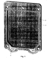
- the Fig. 1 shows a perspective view of a lower part (2) of a housing (1) (see. Fig. 8 ) for electronics or mechatronics with a in a groove (12) (see. Fig. 2 ) inserted circumferential seal (3).
- the housing (1) is installed vertically standing during operation (cf. Figure 8 ), wherein the device for pressure relief (4) is arranged below, is in the following simplistic spoken of the upper and lower part of the housing. In the assembled state are upper and lower Lower part arranged laterally, so that it is also possible to speak of side parts.
- the gasket (3) is made of an elastic material, e.g. Rubber or plastic. Inside the housing (1) mechanical, pneumatic and electronic components are arranged in a known manner (not shown).
- the seal (3) has two pressure relief devices (4), which will be explained in more detail below.
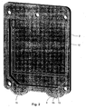
- the Fig. 2 shows the same lower part (2) as the Fig. 1 , but without inserted seal (3). It can be seen that the groove (12) in the lower part of the housing is widened semicircularly in two places, on which the two devices for pressure relief (4) are arranged. To fix these devices are holding pins (9, 10) by corresponding circular openings (7, 8) (see. Fig. 4 ) engage the seal.
- the Fig. 2 further shows two ventilation bores (15, 16), which are located in the lower part (2) of the housing and open from the outside below the device for pressure relief (4) or laterally into this. These holes are to be used in a known manner for testing the tightness of the housing. They further enable a respiratory process or an air exchange between the interior of the housing (1) and the surrounding atmosphere at changing ambient temperatures.
- Fig. 3 In the Fig. 3 is the circumferential seal (3) shown by itself.
- the seal (3) consists largely of a static part (6) whose cross section in the Fig. 6 is shown.
- the seal (3) further has in the lower part of two devices for pressure relief (4), which are provided below or outside with a V-shaped elastic lip profile (5) (see. Fig. 7 ).
- the transition (11) between the static part (6) of the seal (3) and the lip profile (5) is formed continuously with a constant profile height. It can also be seen that the lip profile (5) is double-sided (cf. Fig. 7 ). In the static part (6) of the seal (3), however, this is rectangular with a rounded narrow side (18) formed (see. Fig. 6 ).
- the Fig. 4 shows one of the pressure relief devices (4) in an enlarged view.
- the openings (7, 8) serve, as already mentioned, for receiving holding pins (9, 10) (see Fig. 2 ) and thus for fixing the device for pressure relief (4).
- the cusps (19) further serve to support a bead (21) (see Fig. 5 ) on the back of the seal and for fixing the device for pressure relief.
- the seal (3) is further provided in its static part with distributed over its circumference nubs (13, 14) which prevent falling out of the seal (3) from the groove (12) during assembly.
- a centering of the seal (3) in the groove (12) is achieved by the knobs (13, 14).
- the Fig. 5 shows the device for pressure relief (4) from the Fig. 4 from the back with the bead (21).
- the Fig. 6 shows, as already mentioned above, a cross section through the seal (3) in the static region.
- the seal (3) is rectangular with a rounded narrow side (18).
- the Fig. 7 shows a cross section through the seal (3) in the region of a device for pressure relief (4).
- the lip profile (5) is double-sided. But it is also possible to form the lip profile (5) only on one side (not shown). In this case, the other side is formed as a bead.
- the representation in Fig. 7 further shows one of the bumps (19) and the opposite bead (21).
- the Fig. 8 shows a cross section through the electronics housing (1) in the assembled state with inserted seal (3).
- the pressure relief devices (4) are below.
- the circumferential seal (3) seals the lower part (2) of the housing against an upper part (17) of the housing.
- the seal in the area of a device for pressure relief (4), the seal, as already described, is provided in its outer part with a double-sided lip profile (5). This prevents the penetration of dirty water from the outside, but allows a pressure relief from the inside out.
- the lip profile (5) is fixed by at least one retaining pin (9).
- the retaining pins (9) can also be attached to the upper part (17) of the housing (1) (not shown).
- the lower part of the housing (1) is provided with at least one ventilation bore (16), which opens in the region of the lip profile (5).
- the ventilation bores (16) can also be mounted in the upper part (17) of the housing (not shown).
- the housing (1) has at least in the region of the device for pressure relief (4) one or more stages (20), whereby the penetration of dirt in the region of the lip profile (5) is further complicated by forming a labyrinth.
- the steps are formed and spaced from each other so that they define a stepped gap with their sides facing each other.
- housing (1) Inside the housing (1) are one or more boards for receiving electronic and / or mechatronic components (not shown).
- the labyrinth effect of the housing (1) against the ingress of dirty water is achieved in that the water must first penetrate through the narrow ventilation bore (16) in the space between the lip (5) and bead (21). From there it can only penetrate through the narrow gaps between the retaining pins (9,10) and the openings (7,8) in the adjacent cavity. The water must then pass through the apertures between the protuberances (19) and then through a narrow gap (22) between the two housing halves to enter the housing interior.
- the weight of the water thus penetrated into the interior of the housing (1) then acts on the two lips (5) attached to the lowest point of the housing so that they compress and the water is released back into the environment. In this way, a rapid drainage of the housing is guaranteed.
- the electronics housing can also be designed so that it has a frame-shaped central part containing a board on which electronic and mechatronic components are applied (not shown). On this middle part are then the two in the Fig. 8 shown housing halves or lower part (2) and upper part (17) mounted as a conclusion.
- the above-described inventive seal (3) can be mounted twice, ie on both sides of the middle part.
Landscapes
- Engineering & Computer Science (AREA)
- Microelectronics & Electronic Packaging (AREA)
- Casings For Electric Apparatus (AREA)
Description
- Die Erfindung bezieht sich auf ein Gehäuse, insbesondere für eine Elektronik oder eine Mechatronik, gemäß dem Oberbegriff des Patenanspruchs 1.
- Derartige Gehäuse werden in hohen Stückzahlen gebaut und müssen daher kostengünstig herstellbar sein. Daneben muss aber auch, insbesondere beim Einsatz unter schwierigen Umweltbedingungen, wie z. B. in Kraftfahrzeugen, ein ausreichender Schutz der im Gehäuse angeordneten Elektronik oder Mechatronik gewährleistet sein. Insbesondere muss das unkontrollierte Eindringen von Wasser in das Gehäuse verhindert werden. Hierzu sind solche Gehäuse mit einer umlaufenden, statisch ausgebildeten, elastischen Dichtung versehen, welche ein Oberteil gegen ein Unterteil des Gehäuses im zusammengebauten Zustand abdichtet.
- Daneben ist es aber auch vorteilhaft, wenn das Gehäuse eine kontrollierte Atmung zur umgebenden Atmosphäre gewährleisten kann. Hierdurch wird die Bildung von Kondenswasser im Inneren des Gehäuses bei wechselnden Umgebungstemperaturen verhindert. Weiter wird hierdurch bei Mechatroniken, welche auch mit einer Einspeisung von Druckluft in das Gehäuse arbeiten können, ein eventueller schädlicher Überdruck im Gehäuse verhindert.
- Aus der
DE 197 04 532 A1 sowie derEP 0 772 959 B1 sind wasserdichte Elektronikgehäuse bekannt, welche aus einem Oberteil und einem Unterteil bestehen, wobei die beiden Teile im zusammengebauten Zustand durch eine umlaufende Dichtung gegeneinander abgedichtet sind. Hierdurch wird das Eindringen von Schmutzwasser in das Gehäuse verhindert. Die bekannten Elektronikgehäuse besitzen jedoch keine Öffnung nach außen, die einen Atmungsvorgang ermöglichen könnten. - Aus der
EP 0 961 534 A1 ist ein Elektronikgehäuse bekannt, welches zum Ausgleichen eines Druckunterschiedes zwischen dem Innenraum des Gehäuses und dem Außenraum des Gehäuses mit einer Membran ausgestattet ist. Ferner ist aus derFR 2 831 384 - Aus der
DE 100 22 124 A1 ist weiter ein Gehäuse für ein elektronisches Steuergerät, insbesondere eine Mechatronik, bekannt, welche zur Entlüftung bzw. Belüftung eine Druckentlüftungs-Bohrung aufweist. Diese verhindert die Bildung von Kondenswasser im Gehäuse und hält weiterhin den Druck im Innenraum auf Atmosphärendruck. Auf diese Weise wird ein sonst möglicher Druckanstieg im Innenraum des Gehäuses bei einer leichten Undichtigkeit einer Druckluftzufuhr zu einem Drucksensor verhindert. - Das bekannte Gehäuse mit einer Druckentlastungs-Bohrung hat jedoch den Nachteil, dass durch die Bohrung eventuell Schmutzwasser in den Innenraum eindringen kann. Hierdurch können empfindliche Bauelemente beschädigt werden.
- Der Erfindung liegt die Aufgabe zugrunde, ein Gehäuse, insbesondere für eine Elektronik oder eine Mechatronik, anzugeben, welches gegen das Eindringen von Schmutzwasser weitgehend geschützt ist, aber gleichzeitig eine schnelle Druckentlastung nach außen bei einem eventuellen Überdruck im Gehäuse zulässt.
- Diese Aufgabe wird durch die im Patentanspruch 1 enthaltene Erfindung gelöst. Die Unteransprüche enthalten zweckmäßige Weiterbildungen.
- Durch die erfindungsgemäße Integration einer Vorrichtung zur Druckentlastung in die umlaufende Dichtung zwischen Oberteil und Unterteil wird zum einen durch eine Labyrinth-Wirkung eine weitgehende Abdichtung des Gehäuses gegen äußeres Schmutzwasser erzielt, aber durch ein Lippenprofil auch ein schnelles Ablassen eines Überdruckes vom Innenraum ins Freie ermöglicht. Da damit eine besondere Vorrichtung (Überdruckventil) eingespart wird, ist das Gehäuse kostengünstig zu fertigen.
- Die Erfindung wird im Folgenden anhand einer Zeichnung näher erläutert. Diese zeigt in
- Fig. 1
- das Unterteil des erfindungsgemäßen Elek- tronikgehäuses mit eingelegter Ringdich- tung,
- Fig. 2
- das Unterteil des Gehäuses ohne eingelegte Ringdichtung,
- Fig. 3
- die Ringdichtung mit zwei integrierten Vorrichtungen zur Druckentlastung,
- Fig. 4
- eine Vorrichtung zur Druckentlastung in vergrößerter Darstellung.
- Fig. 5
- die Vorrichtung zur Druckentlastung aus
Fig. 4 von unten betrachtet - Fig. 6
- einen Querschnitt durch die Ringdichtung im übrigen Bereich
- Fig. 7
- einen Querschnitt durch die Ringdichtung im Bereich der Vorrichtung zur Druckentlastung,
- Fig. 8
- das Elektronikgehäuse im zusammengebauten Zustand mit Ober- und Unterteil sowie eingelegter Ringdichtung.
- Die
Fig. 1 zeigt eine perspektivische Darstellung eines Unterteils (2) eines Gehäuses (1) (vergl.Fig. 8 ) für eine Elektronik oder eine Mechatronik mit einer in eine Nut (12) (vgl.Fig. 2 ) eingelegten umlaufenden Dichtung (3). - Obwohl das Gehäuse (1) im Betrieb senkrecht stehend eingebaut wird (vergl.
Fig.8 ), wobei die Vorrichtung zur Druckentlastung (4) unten angeordnet ist, wird im Folgenden vereinfachend von Ober- und Unterteil des Gehäuses gesprochen. Im montierten Zustand sind Oberund Unterteil seitlich angeordnet, so dass auch von Seitenteilen gesprochen werden kann. - Die Dichtung (3) ist aus einem elastischen Material, z.B. Gummi oder Kunststoff, gefertigt. Im Inneren des Gehäuses (1) sind in bekannter Weise mechanische, pneumatische und elektronische Bauelemente angeordnet (nicht dargestellt). Die Dichtung (3) weist zwei Vorrichtungen zur Druckentlastung (4) auf, die im folgenden noch näher erläutert werden.
- Die
Fig. 2 zeigt das gleiche Unterteil (2) wie dieFig. 1 , jedoch ohne eingelegte Dichtung (3). Man erkennt, dass die Nut (12) im unteren Teil des Gehäuses an zwei Stellen halbkreisförmig erweitert ist, an denen die beiden Vorrichtungen zur Druckentlastung (4) angeordnet sind. Zur Fixierung dieser Vorrichtungen dienen Haltezapfen (9, 10), die durch entsprechende kreisförmige Durchbrüche (7, 8) (vgl.Fig. 4 ) der Dichtung eingreifen. - Die
Fig. 2 zeigt weiter zwei Beatmungsbohrungen (15, 16), welche sich im Unterteil (2) des Gehäuses befinden und von außen unterhalb der Vorrichtung zur Druckentlastung (4) bzw. seitlich in diese münden. Diese Bohrungen sind in bekannter Weise auch zur Prüfung der Dichtigkeit des Gehäuses zu verwenden. Sie ermöglichen weiter einen Atmungsvorgang bzw. einen Luftaustausch zwischen dem Innenraum des Gehäuses (1) und der umgebenden Atmosphäre bei wechselnden Umgebungstemperaturen. - In der
Fig. 3 ist die umlaufende Dichtung (3) für sich dargestellt. Die Dichtung (3) besteht größtenteils aus einem statischen Teil (6), dessen Querschnitt in derFig. 6 dargestellt ist. - Die Dichtung (3) besitzt weiter im unteren Teil zwei Vorrichtungen zur Druckentlastung (4), welche unten bzw. außen mit einem V-förmigen elastischen Lippenprofil (5) versehen sind (vergl.
Fig. 7 ). Der Übergang (11) zwischen dem statischen Teil (6) der Dichtung (3) und dem Lippenprofil (5) ist stetig mit konstanter Profilhöhe ausgebildet. Weiter ist erkennbar, dass das Lippenprofil (5) doppelseitig ausgebildet ist (vgl. auchFig. 7 ). Im statischen Teil (6) der Dichtung (3) ist diese dagegen rechteckig mit einer abgerundeten Schmalseite (18) ausgebildet (vgl.Fig. 6 ). - Am Innenrand der Dichtung im Bereich der Vorrichtungen zur Druckentlastung (4) sind mehrere Höcker (19) angeordnet, zwischen denen ein Luftdurchtritt möglich ist.
- Die
Fig. 4 zeigt eine der Vorrichtungen zur Druckentlastung (4) in vergrößerter Darstellung. Die Durchbrüche (7, 8) dienen, wie bereits gesagt, zur Aufnahme von Haltezapfen (9, 10) (sieheFig. 2 ) und somit zur Fixierung der Vorrichtung zur Druckentlastung (4). - Zwischen den diskreten Höckern (19) ist ein Luftdurchtritt (Labyrinth-Dichtung) sowohl vom Gehäuse-Inneren nach außen als auch umgekehrt möglich. Die Höcker (19) dienen weiter zur Unterstützung einer Wulst (21) (siehe
Fig. 5 ) auf der Rückseite der Dichtung und zur Fixierung der Vorrichtung zur Druckentlastung. - Die Dichtung (3) ist in ihrem statischen Teil weiter mit über ihren Umfang verteilten Noppen (13, 14) versehen, welche bei der Montage ein Herausfallen der Dichtung (3) aus der Nut (12) verhindern. Außerdem wird durch die Noppen (13, 14) eine Zentrierung der Dichtung (3) in der Nut (12) erreicht.
- Die
Fig. 5 zeigt die Vorrichtung zur Druckentlastung (4) aus derFig. 4 von der Rückseite mit der Wulst (21). - Die
Fig. 6 zeigt, wie oben bereits erwähnt, einen Querschnitt durch die Dichtung (3) im statischen Bereich. Hier ist die Dichtung (3) rechteckig mit einer abgerundeten Schmalseite (18) ausgebildet. - Die
Fig. 7 zeigt einen Querschnitt durch die Dichtung (3) im Bereich einer Vorrichtung zur Druckentlastung (4). Wie man sieht, ist das Lippenprofil (5) doppelseitig ausgebildet. Es ist aber auch möglich, das Lippenprofil (5) nur einseitig auszubilden (nicht dargestellt). In diesem Fall ist die andere Seite als Wulst ausgebildet. Die Darstellung inFig. 7 zeigt weiter einen der Höcker (19) und die gegenüberliegende Wulst (21). - Die
Fig. 8 zeigt einen Querschnitt durch das Elektronikgehäuse (1) im zusammengebauten Zustand mit eingelegter Dichtung (3). Wie bereits gesagt, ist das Gehäuse senkrecht stehend angeordnet, wobei die Vorrichtungen zur Druckentlastung (4) unten liegen. Die umlaufende Dichtung (3) dichtet das Unterteil (2) des Gehäuses gegen ein Oberteil (17) des Gehäuses ab. Im Bereich einer Vorrichtung zur Druckentlastung (4) ist die Dichtung, wie bereits beschrieben, in ihrem äußeren Teil mit einem doppelseitigen Lippenprofil (5) versehen. Diese verhindert ein Eindringen von Schmutzwasser von außen, ermöglicht aber eine Druckentlastung von innen nach außen. - Wie bereits beschrieben, wird das Lippenprofil (5) durch mindestens einen Haltezapfen (9) fixiert. Die Haltezapfen (9) können auch am Oberteil (17) des Gehäuses (1) angebracht sein (nicht dargestellt).
- Für Druck-Prüfungen sowie zum Luftaustausch ist das Unterteil des Gehäuses (1) mit mindestens einer Beatmungsbohrung (16) versehen, welche im Bereich des Lippenprofils (5) mündet. Die Beatmungsbohrungen (16) können auch im Oberteil (17) des Gehäuses angebracht sein (nicht dargestellt).
- Das Gehäuse (1) besitzt mindestens im Bereich der Vorrichtung zur Druckentlastung (4) eine oder mehrere Stufen (20), wodurch das Eindringen von Schmutz in den Bereich des Lippenprofils (5) durch Ausbildung eines Labyrinths weiter erschwert wird. Die Stufen sind so ausgebildet und zueinander beabstandet, dass sie mit ihren einander zugewandten Seiten einen treppenförmigen Spalt begrenzen.
- Im Inneren des Gehäuses (1) befinden sich eine oder mehrere Platinen zur Aufnahme von elektronischen und/oder mechatronischen Bauelementen (nicht dargestellt).
- Anhand der
Fig. 8 soll die Funktionsweise des erfindungsgemäßen Elektronik- bzw. Mechatronikgehäuses näher erläutert werden. - Falls sich im Inneren des Gehäuses (1) durch eine Undichtigkeit in einer pneumatischen Leitung ein Überdruck aufbauen sollte, kann dieser unter Zusammendrücken des elastischen Lippenprofils (5) leicht nach außen entweichen. Ein Eindringen von Luft in umgekehrter Richtung wird dagegen durch das gespreizte Lippenprofil (5) verhindert. Ein solches Eindringen von Außenluft zu Atmungszwecken wird jedoch durch die sehr engen Beatmungsbohrungen (16) ermöglicht.
- Die Labyrinthwirkung des Gehäuses (1) gegen Eindringen von Schmutzwasser wird dadurch erzielt, dass das Wasser zunächst durch die enge Beatmungsbohrung (16) in den Raum zwischen Lippe (5) und Wulst (21) eindringen muss. Von dort aus kann es nur durch die engen Spalte zwischen den Haltezapfen (9,10) und den Durchbrüchen (7,8) in den benachbarten Hohlraum eindringen. Das Wasser muss dann weiter durch die Durchbrüche zwischen den Höckern (19) und danach durch einen engen Spalt (22) zwischen den beiden Gehäusehälften hindurch, um in den Gehäuse- Innenraum zu gelangen.
- Das Gewicht des derart in das Innere des Gehäuses (1) eingedrungenen Wassers wirkt sodann in der Weise auf die beiden am tiefsten Punkt des Gehäuses angebrachten Lippen (5), dass diese sich zusammendrücken, und das Wasser wieder in die Umgebung freigegeben wird. Auf diese Weise ist ein schnelles Entwässern des Gehäuses gewährleistet.
- Das Elektronikgehäuse kann auch so ausgebildet sein, dass es ein rahmenförmiges Mittelteil aufweist, das eine Platine enthält, auf welcher elektronische sowie mechatronische Bauteile aufgebracht sind (nicht dargestellt). Auf dieses Mittelteil sind dann die beiden in der
Fig. 8 dargestellten Gehäusehälften bzw. Unterteil (2) und Oberteil (17) als Abschluss aufgesetzt. In diesem Fall kann die oben beschriebene erfindungsgemäße Dichtung (3) zweifach, also auf beiden Seiten des Mittelteils, angebracht sein.
Claims (10)
- Elektronikgehäuse (1), insbesondere zur Aufnahme einer Elektronik oder einer Mechatronik, mit einem Oberteil (17) und einem Unterteil (2), oder mit mehreren zusammengebauten Gehäuseteilen, und mit mindestens einer umlaufenden, statisch ausgebildeten Dichtung (3), welche das Oberteil (17) gegen das Unterteil (2) oder gegen weitere Gehäuseteile im zusammengebauten Zustand abdichtet, dadurch gekennzeichnet, dass in die Dichtung (3) mindestens eine Vorrichtung zur Druckentlastung (4) integriert ist, welche mit dem Ober- und/oder dem Unterteil (17,2) oder mit weiteren Gehäuseteilen des Elektronikgehäuses (1) zusammenwirkt, wobei die Vorrichtung zur Druckentlastung (4) als zumindest in einem Teilstück der Dichtung (3) ausgebildetes elastisches Lippenprofil (5) realisiert ist, welches am Oberteil (17) und/oder am Unterteil (2) dichtend anliegt und ein durch Überdruck im Gehäuseinneren in eine Offenstellung bringbares Rückschlagventil bildet.
- Gehäuse nach Anspruch 1, dadurch gekennzeichnet, dass es senkrecht montiert ist, wobei die Vorrichtung zur Druckentlastung (4) unten angeordnet ist.
- Gehäuse nach Anspruch 1, dadurch gekennzeichnet, dass das Lippenprofil (5) V-förmig elastisch ausgebildet ist.
- Gehäuse nach einem oder mehreren der Ansprüche 1 bis 3, dadurch gekennzeichnet, dass der Übergang (11) zwischen dem statischen Teil (6) der Dichtung (3) und dem Lippenprofil (5) stetig ausgebildet ist.
- Gehäuse nach einem oder mehreren der Ansprüche 1 bis 4, dadurch gekennzeichnet, dass der Übergang (11) eine konstante Profilhöhe aufweist.
- Gehäuse nach einem oder mehreren der Ansprüche 1 bis 5, dadurch gekennzeichnet, dass die Vorrichtung zur Druckentlastung (4) mindestens einen Durchbruch (7,8) aufweist, in den mindestens ein am Unterteil (2) des Gehäuses (1) angebrachter Haltezapfen (9,10) eingreift.
- Gehäuse nach einem oder mehreren der Ansprüche 1 bis 6, dadurch gekennzeichnet, dass der Querschnitt des statischen Teils der Dichtung (3) rechteckig mit einer abgerundeten Schmalseite (18) ausgebildet ist.
- Gehäuse nach einem oder mehreren der Ansprüche 1 bis 7, dadurch gekennzeichnet, dass die Dichtung (3) in eine Nut (12) des Unterteils (2) des Gehäuses (1) eingebettet ist.
- Gehäuse nach einem oder mehreren der Ansprüche 1 bis 8, dadurch gekennzeichnet, dass die Dichtung (3) mehrere über ihren Umfang verteilte, seitlich hervorstehende Noppen (13,14) aufweist, die sich an den Seitenwänden der Nut (12) abstützen und die ein Herausfallen der Dichtung (3) aus der Nut (12) verhindern.
- Gehäuse nach einem oder mehreren der Ansprüche 1 bis 9, dadurch gekennzeichnet, dass es mit einer oder mehreren Beatmungsbohrungen (15,16) versehen ist, welche seitlich in die Vorrichtung zur Druckentlastung (4) einmünden.
Applications Claiming Priority (2)
| Application Number | Priority Date | Filing Date | Title |
|---|---|---|---|
| DE102004028199 | 2004-06-04 | ||
| DE102004028199A DE102004028199A1 (de) | 2004-06-04 | 2004-06-04 | Elektronikgehäuse |
Publications (3)
| Publication Number | Publication Date |
|---|---|
| EP1603378A2 EP1603378A2 (de) | 2005-12-07 |
| EP1603378A3 EP1603378A3 (de) | 2008-04-16 |
| EP1603378B1 true EP1603378B1 (de) | 2010-12-29 |
Family
ID=34934327
Family Applications (1)
| Application Number | Title | Priority Date | Filing Date |
|---|---|---|---|
| EP05005827A Expired - Lifetime EP1603378B1 (de) | 2004-06-04 | 2005-03-17 | Elektronikgehäuse |
Country Status (3)
| Country | Link |
|---|---|
| US (1) | US8757415B2 (de) |
| EP (1) | EP1603378B1 (de) |
| DE (2) | DE102004028199A1 (de) |
Families Citing this family (8)
| Publication number | Priority date | Publication date | Assignee | Title |
|---|---|---|---|---|
| US20020073545A1 (en) * | 2000-12-19 | 2002-06-20 | Adc Telecommunications, Inc. | Enhanced heat transfer for housings |
| US8437134B2 (en) * | 2010-01-13 | 2013-05-07 | Honda Motor Co., Ltd. | Housing structure for vehicle electronic control unit |
| JP5330292B2 (ja) * | 2010-02-26 | 2013-10-30 | 日本電産サンキョー株式会社 | カードリーダ |
| DE102010015674A1 (de) | 2010-04-21 | 2011-10-27 | Wabco Gmbh | Ein Gehäuse mit einem Verformungsbereich zum Druckausgleich sowie eine Anordnung eines Dichtungselements in dem Gehäuse |
| DE102016208276A1 (de) * | 2016-05-13 | 2017-11-16 | Mahle International Gmbh | Stelleinrichtung |
| DE102019131441B3 (de) * | 2019-11-21 | 2020-12-31 | Audi Ag | Elektronikgehäuse zur Aufnahme einer elektrischen Komponente |
| EP3923428B1 (de) * | 2020-06-10 | 2022-12-14 | ABB Schweiz AG | Druckentlastungsanordnung |
| JP7321305B2 (ja) * | 2022-01-12 | 2023-08-04 | 三菱電機株式会社 | 電力変換装置 |
Family Cites Families (18)
| Publication number | Priority date | Publication date | Assignee | Title |
|---|---|---|---|---|
| US3290047A (en) * | 1963-02-11 | 1966-12-06 | North American Aviation Inc | Relief seal with dual sealing surfaces |
| US5349506A (en) * | 1984-09-06 | 1994-09-20 | Mag Instrument, Inc. | Miniature flashlight |
| DE3618269A1 (de) * | 1986-05-30 | 1987-12-03 | Boehm Hans Georg Dipl Phys Dr | Dampfdruckkochtopf mit einer den topfinnenraum gegen druckabfall sichernden dichtung |
| US5187621A (en) * | 1991-03-25 | 1993-02-16 | Quantum Corporation | RFI/EMI reduction for head and disk assembly |
| EP0772959B1 (de) * | 1994-07-28 | 1998-03-18 | Siemens Aktiengesellschaft | Wasserdichtes gehäuse mit einer steckverbindung zum schutz von elektronikschaltkreisen |
| DE19704532C2 (de) * | 1997-02-06 | 1998-12-03 | Siemens Ag | Gehäuse mit Rahmendichtung |
| WO1999030544A1 (en) * | 1997-12-09 | 1999-06-17 | Tokai Kogyo Co., Ltd. | An inner and outer pressure equalization structure for an airtight case |
| US6158745A (en) * | 1998-03-20 | 2000-12-12 | Pelican Products, Inc. | Fluid pressure relief seal for liquid and fluid-tight compartments |
| DE19902283C1 (de) * | 1999-01-21 | 2000-07-13 | Freudenberg Carl Fa | Verschlußdeckel |
| DE29918158U1 (de) * | 1999-10-14 | 2000-01-20 | Gummi Jaeger Kg Gmbh & Cie | Gehäuse zur Aufnahme elektrischer Elemente |
| DE10022124B4 (de) | 2000-05-06 | 2010-01-14 | Wabco Gmbh | Elektronisches Steuergerät |
| DE10047328A1 (de) * | 2000-09-25 | 2002-04-11 | Continental Teves Ag & Co Ohg | Ausgleichsbehälter mit in den Deckel eingeformten Luftkanal |
| US6536775B1 (en) * | 2001-01-30 | 2003-03-25 | Dana Corporation | Boundary gasket with integral bolt thread seals |
| US7413099B2 (en) * | 2001-06-08 | 2008-08-19 | Shin-Etsu Polymer Co., Ltd. | Sealing element with a protruding part approximately obliquely outward and a hermetic container using the same |
| KR100406640B1 (ko) * | 2001-10-10 | 2003-11-21 | 삼성광주전자 주식회사 | 밀폐형 압축기의 밸브장치 |
| DE10151413B4 (de) * | 2001-10-18 | 2005-05-19 | Siemens Ag | Dichtung zum Abdichten eines Spaltes zwischen zwei abzudichtenden Gehäuseteilen, sowie ein Gehäuse eines Steuergerätes eines Kraftfahrzeugs |
| US20040094554A1 (en) * | 2002-06-24 | 2004-05-20 | Grybush Anthony F. | Vented fuel tank cap |
| US7578407B2 (en) * | 2004-04-18 | 2009-08-25 | Entegris, Inc. | Wafer container with sealable door |
-
2004
- 2004-06-04 DE DE102004028199A patent/DE102004028199A1/de not_active Withdrawn
-
2005
- 2005-03-17 DE DE502005010740T patent/DE502005010740D1/de not_active Expired - Lifetime
- 2005-03-17 EP EP05005827A patent/EP1603378B1/de not_active Expired - Lifetime
- 2005-05-19 US US11/132,723 patent/US8757415B2/en active Active
Also Published As
| Publication number | Publication date |
|---|---|
| DE102004028199A1 (de) | 2005-12-22 |
| US20050269321A1 (en) | 2005-12-08 |
| DE502005010740D1 (de) | 2011-02-10 |
| US8757415B2 (en) | 2014-06-24 |
| EP1603378A3 (de) | 2008-04-16 |
| EP1603378A2 (de) | 2005-12-07 |
Similar Documents
| Publication | Publication Date | Title |
|---|---|---|
| EP1181505B1 (de) | Sensorbaugruppe mit einem an einer wand montierbaren gehäuse | |
| EP1034692B1 (de) | Belüftungseinrichtung, insbesondere für elektrische steuergeräte | |
| DE102017214754B4 (de) | Vorrichtung zum Druckausgleich in einem Gehäuse | |
| DE4426812A1 (de) | Wasserdichtes Gehäuse mit Steckverbindung zum Schutz von Elektronikschaltkreisen | |
| DE10162497A1 (de) | Tragbares elektronisches Gerät | |
| DE102012112098A1 (de) | Anordnung zum Druckausgleich eines Gehäuses | |
| DE102020134548B4 (de) | Notentgasungsvorrichtung | |
| EP2465152A1 (de) | Verschlussvorrichtung für ein gegenüber der umgebung abgeschlossenes gehäuse und gehäuse | |
| DE19651117A1 (de) | Gasentlüftungsvorrichtung für einen Kraftstofftank | |
| DE19715573A1 (de) | Gehäuse | |
| DE112015003659T5 (de) | Gehäuse für eine elektronische Steuerungseinheit | |
| DE2902169C2 (de) | Regen- und spritzwassergeschütztes Gehäuse zur Aufnahme von elektrischen Geräten | |
| DE19523454B4 (de) | Be- und Entlüftungsvorrichtung für Getriebe und Achsen | |
| DE202023103907U1 (de) | Gehäuse für einen Kältemittelgasleckdetektionssensor und Kältemittelgasleckdetektionssensor mit einem Gehäuse | |
| EP1603378A2 (de) | Elektronikgehäuse | |
| DE102008016347B4 (de) | Elektronikgehäuse | |
| DE102007030789A1 (de) | Vorrichtung zum Abdichten eines geschlossenen Raumes | |
| DE102018118660A1 (de) | Elektronische vorrichtung, die an einer industriemaschine angebracht ist | |
| DE102022211113A1 (de) | Druckausgleichselement für ein Batteriesystem, Fahrzeug-Batteriesystem sowie Fahrzeug mit einem Batteriesystem und Druckausgleichselement | |
| DE102006042565A1 (de) | Fahrzeugreifendruckmesseinheit | |
| DE20310095U1 (de) | Vorrichtung zum Schutz einer Gebäudeöffnung | |
| DE1665081A1 (de) | Kasten fuer elektrische Geraete,vorzugsweise Befehls- und Meldegeraete | |
| DE29613784U1 (de) | Kontaktsaugplatte mit Kontaktsaugventil | |
| DE102005038687A1 (de) | Gehäusesystem für Elektronikgeräte | |
| DE102005000074A1 (de) | Aufnahmegehäuse für ein Handwerkzeuggerät |
Legal Events
| Date | Code | Title | Description |
|---|---|---|---|
| PUAI | Public reference made under article 153(3) epc to a published international application that has entered the european phase |
Free format text: ORIGINAL CODE: 0009012 |
|
| AK | Designated contracting states |
Kind code of ref document: A2 Designated state(s): AT BE BG CH CY CZ DE DK EE ES FI FR GB GR HU IE IS IT LI LT LU MC NL PL PT RO SE SI SK TR |
|
| AX | Request for extension of the european patent |
Extension state: AL BA HR LV MK YU |
|
| RAP1 | Party data changed (applicant data changed or rights of an application transferred) |
Owner name: WABCO GMBH |
|
| PUAL | Search report despatched |
Free format text: ORIGINAL CODE: 0009013 |
|
| AK | Designated contracting states |
Kind code of ref document: A3 Designated state(s): AT BE BG CH CY CZ DE DK EE ES FI FR GB GR HU IE IS IT LI LT LU MC NL PL PT RO SE SI SK TR |
|
| AX | Request for extension of the european patent |
Extension state: AL BA HR LV MK YU |
|
| RIC1 | Information provided on ipc code assigned before grant |
Ipc: H05K 5/00 20060101AFI20050926BHEP Ipc: F16J 15/06 20060101ALI20080307BHEP Ipc: H05K 5/06 20060101ALI20080307BHEP |
|
| 17P | Request for examination filed |
Effective date: 20081016 |
|
| AKX | Designation fees paid |
Designated state(s): DE FR IT NL SE |
|
| 17Q | First examination report despatched |
Effective date: 20090826 |
|
| GRAP | Despatch of communication of intention to grant a patent |
Free format text: ORIGINAL CODE: EPIDOSNIGR1 |
|
| GRAS | Grant fee paid |
Free format text: ORIGINAL CODE: EPIDOSNIGR3 |
|
| GRAA | (expected) grant |
Free format text: ORIGINAL CODE: 0009210 |
|
| AK | Designated contracting states |
Kind code of ref document: B1 Designated state(s): DE FR IT NL SE |
|
| REF | Corresponds to: |
Ref document number: 502005010740 Country of ref document: DE Date of ref document: 20110210 Kind code of ref document: P |
|
| REG | Reference to a national code |
Ref country code: DE Ref legal event code: R096 Ref document number: 502005010740 Country of ref document: DE Effective date: 20110210 |
|
| REG | Reference to a national code |
Ref country code: NL Ref legal event code: T3 |
|
| REG | Reference to a national code |
Ref country code: SE Ref legal event code: TRGR |
|
| PLBE | No opposition filed within time limit |
Free format text: ORIGINAL CODE: 0009261 |
|
| STAA | Information on the status of an ep patent application or granted ep patent |
Free format text: STATUS: NO OPPOSITION FILED WITHIN TIME LIMIT |
|
| 26N | No opposition filed |
Effective date: 20110930 |
|
| REG | Reference to a national code |
Ref country code: DE Ref legal event code: R097 Ref document number: 502005010740 Country of ref document: DE Effective date: 20110930 |
|
| REG | Reference to a national code |
Ref country code: DE Ref legal event code: R081 Ref document number: 502005010740 Country of ref document: DE Owner name: WABCO EUROPE BVBA, BE Free format text: FORMER OWNER: WABCO GMBH, 30453 HANNOVER, DE Effective date: 20121214 |
|
| REG | Reference to a national code |
Ref country code: FR Ref legal event code: TP Owner name: WABCO EUROPE BVBA, BE Effective date: 20130717 |
|
| REG | Reference to a national code |
Ref country code: NL Ref legal event code: SD Effective date: 20150114 |
|
| REG | Reference to a national code |
Ref country code: FR Ref legal event code: PLFP Year of fee payment: 12 |
|
| REG | Reference to a national code |
Ref country code: FR Ref legal event code: PLFP Year of fee payment: 13 |
|
| REG | Reference to a national code |
Ref country code: FR Ref legal event code: PLFP Year of fee payment: 14 |
|
| REG | Reference to a national code |
Ref country code: DE Ref legal event code: R081 Ref document number: 502005010740 Country of ref document: DE Owner name: ZF CV SYSTEMS EUROPE BV, BE Free format text: FORMER OWNER: WABCO EUROPE BVBA, BRUXELLES, BE |
|
| P01 | Opt-out of the competence of the unified patent court (upc) registered |
Effective date: 20230528 |
|
| PGFP | Annual fee paid to national office [announced via postgrant information from national office to epo] |
Ref country code: NL Payment date: 20240108 Year of fee payment: 20 |
|
| PGFP | Annual fee paid to national office [announced via postgrant information from national office to epo] |
Ref country code: DE Payment date: 20231229 Year of fee payment: 20 |
|
| PGFP | Annual fee paid to national office [announced via postgrant information from national office to epo] |
Ref country code: SE Payment date: 20240103 Year of fee payment: 20 Ref country code: IT Payment date: 20240212 Year of fee payment: 20 Ref country code: FR Payment date: 20240103 Year of fee payment: 20 |
|
| REG | Reference to a national code |
Ref country code: DE Ref legal event code: R071 Ref document number: 502005010740 Country of ref document: DE |
|
| REG | Reference to a national code |
Ref country code: NL Ref legal event code: MK Effective date: 20250316 |
|
| REG | Reference to a national code |
Ref country code: SE Ref legal event code: EUG |