EP1601128A2 - Verfahren und Vorrichtung zur bewegungskompensierten Rauschschätzung bei mobilen drahtlosen Übertragungssystemen - Google Patents
Verfahren und Vorrichtung zur bewegungskompensierten Rauschschätzung bei mobilen drahtlosen Übertragungssystemen Download PDFInfo
- Publication number
- EP1601128A2 EP1601128A2 EP05009416A EP05009416A EP1601128A2 EP 1601128 A2 EP1601128 A2 EP 1601128A2 EP 05009416 A EP05009416 A EP 05009416A EP 05009416 A EP05009416 A EP 05009416A EP 1601128 A2 EP1601128 A2 EP 1601128A2
- Authority
- EP
- European Patent Office
- Prior art keywords
- reference symbols
- pred
- receiver
- value
- motion
- Prior art date
- Legal status (The legal status is an assumption and is not a legal conclusion. Google has not performed a legal analysis and makes no representation as to the accuracy of the status listed.)
- Granted
Links
Images
Classifications
-
- H—ELECTRICITY
- H04—ELECTRIC COMMUNICATION TECHNIQUE
- H04L—TRANSMISSION OF DIGITAL INFORMATION, e.g. TELEGRAPHIC COMMUNICATION
- H04L1/00—Arrangements for detecting or preventing errors in the information received
- H04L1/20—Arrangements for detecting or preventing errors in the information received using signal quality detector
-
- H—ELECTRICITY
- H04—ELECTRIC COMMUNICATION TECHNIQUE
- H04L—TRANSMISSION OF DIGITAL INFORMATION, e.g. TELEGRAPHIC COMMUNICATION
- H04L27/00—Modulated-carrier systems
- H04L27/26—Systems using multi-frequency codes
- H04L27/2601—Multicarrier modulation systems
- H04L27/2647—Arrangements specific to the receiver only
Definitions
- the invention relates to a method and a device for motion-compensated noise estimation in mobile wireless Transmission systems in which by a transmitter reference symbols to be sent out.
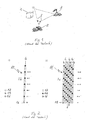
- Wireless transmission systems have, as in Figure 1 schematically shown, usually at least one transmitter 1 and a receiver 2 on.
- the transmitter 1 and the receiver 2 is mobile, which in the Representation by the movable receiver 2 for expression comes.
- a data signal is sent, which via a transmission channel, also called a radio channel is, reaches the receiver 2.
- the transmission properties This transmission channel are by the respective existing Transmission situation specified.
- the Transmission situation significantly affected by the distance between transmitter 1 and receiver 2, reflections from data or radio signals to buildings, mountains, vehicles or other obstacles 3 as well as by the on the Doppler effect based frequency shift at non-vanishing relative Speed between transmitter 1 and receiver 2.
- the main transmission characteristics of the transmission channel First, its transfer function is to be expected.
- the frequency spectrum of the signal received in the receiver is calculated from the frequency spectrum of the sent Data signal by multiplication with this transfer function.
- the transfer function therefore provides a link between the transmitted data signal and the received signal.
- OFDM Orthogonal Frequency Division Multiplexing
- the receiver-side reconstruction of the data signal will affected by noise and noise components, which the in the receiver received signal are superimposed.
- the noise is mainly due to thermal movements of elementary particles caused.
- the causes of disturbances are varied nature and can be, for example, by simultaneous Receiving a foreign station are caused.
- noise will speak only of noise, including below always the mentioned disturbances are to be understood.
- Ensuring the highest possible quality of the receiving end reconstructed data signal therefore requires a Analysis of the received data signal with regard to the interference effects Noise and time variance of the transmission channel and a appropriate adaptation of the recipient to the respective present Transmission properties.
- noise components estimated in this way in the received data signal However, at the same time they contain extraneous noise the temporal change of the transmission channel or its transmission properties originate. In the reconstruction of the originally transmitted data signal based on the results of Noise estimation results in these portions of the time variance of the transmission channel to a distortion of the actual result. In addition, they hinder the received data signal contained noise components an accurate determination of the time variance the transmission channel. Is this about a relative speed is appreciated between sender and receiver, so is the result of this estimation errors due to noise subjected.
- the invention is thus based on the problem of a method to provide with which a motion-compensated Noise estimation in mobile wireless transmission systems, at which of a transmitter reference symbols emitted be possible.
- the invention is based on the problem of a device to provide with which a motion-compensated Noise estimation in mobile wireless transmission systems, at which of a transmitter reference symbols to be sent out is possible.
- the idea underlying the invention is, from at least one part of the time medium or directly to each other following in a receiver received reference symbols by forming a statistical moment, which for example An arithmetic mean is a static one
- An arithmetic mean is a static one
- To determine the proportion of received reference symbols continue by comparing at least two middle or immediate temporally successive reference symbols one determine dynamic proportion of received reference symbols, from the static and dynamic parts of the reference symbols a predictive value for the next received Reference symbol after receiving this next reference symbol by comparing the received reference symbol using the predictive value to determine a prediction error and from the prediction error, an estimate of the noise a transmitted in a transmission channel data signal determine.
- the calculation of the predictive value is under Consideration of the prediction error of temporal changes adapted to the transmission channel.
- Figure 1 shows the basic structure of a mobile wireless Transmission system, as already described above.
- a transmitted from the transmitter 1 data signal passes various, the transmission channel 5 forming paths to the receiver 2, where it partly reflects on obstacles 3 becomes.
- FIG. 2 a shows a data signal 10 with a single carrier frequency f 0 , into which reference symbols 14, 16 are inserted at equal time intervals between information symbols 12. As indicated by the running index k, a reference symbol 14, 16 is followed by three information symbols 12. The currently received new reference symbol 16 carries the running index k, so that reference symbols with an index value smaller than k have already been received in a receiver and optionally stored there ,
- FIG. 2b shows an OFDM data signal with multicarrier transmission.
- a multiplicity of carrier frequencies f 0 , f 1 , f 2 , f 3 , f 4 , f 5 , f 6 with a fixed frequency spacing are used, each carrying data signals.
- Reference symbols 14, 16 are transmitted between information symbols 12 on each of these carrier frequencies f 0 , f 1 , f 2 , f 3 , f 4 , f 5 , f 6 extending along the frequency axis f.
- Such OFDM data signals are used, for example, in Digital Audio Broadcasting (DAB) or digital image transmission systems such as Digital Video Broadcasting Terrestrial (DVB-T).
- DAB Digital Audio Broadcasting
- DVD-T Digital Video Broadcasting Terrestrial
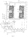
- Figure 3 shows a schematic representation of an embodiment a device according to the invention for motion-compensated Noise estimation in mobile wireless transmission systems, in which of a transmitter 1 reference symbols 14, 16 are emitted similarly as shown in Figure 2a.
- the method can also be based on multi-carrier frequency signals how the OFDM signal of Figure 2b is applied by the Method is applied to each carrier frequency, or also on only one carrier frequency and a takeover of the result the noise estimate on the other carrier frequencies, if necessary taking into account the different values of Carrier frequencies, takes place.
- At the beginning of a process cycle at least a portion of time-centered or immediately consecutive in a receiver 2 received reference symbols s - 1 ' s -2 ' ..., s -L by forming a statistical moment a static component s avg of the received reference symbols s -1 , s -2 , ..., s -L determined.
- the hyphen in the notation makes it clear that these are complex quantities.
- the statistical mean of the arithmetic mean value of the reference symbols last received consecutively at a distance T in time s -1 , s -2 , ..., s -L determined. Furthermore, the determination of a dynamic share takes place s motion of the received reference symbols s -1 , s - 2 , ..., s -L by comparing the temporally successive reference symbols s - ⁇ and s -1 , where L ⁇ ⁇ > 1, ⁇ is integer and in Figure 3 as s - ⁇ s -4 was chosen. The comparison is preferably carried out by subtraction or
- a prediction value takes place s pred for the next received reference symbol s 0 from the static s avg and the dynamic share s motion of the reference symbols s -1 , s -2 , ..., s -L .
- the specific predictive value s pred becomes the reference symbol actually received next s 0 , which is preferred by subtracting the prediction value s pred from the received reference symbol s 0 happens.
- the result is a prediction error s err as the difference between the predictive value s pred and received reference symbol s 0 .
- an estimated value for the noise P noise of a data signal 10 transmitted in a transmission channel 5 is determined. Preferably, this is done, as shown in Figure 3, by forming the absolute square of s err and the averaging of the resulting result with the squares of prediction errors determined in previous procedural cycles.
- the transmission channel can have a temporal variance, it is not possible to predict the value s pred always in the same way from the static part s avg and the dynamic share s to form motion . Therefore, the way of forming the prediction value s pred taking into account the prediction error s err adapted to temporal changes of the transmission channel 5.
- this adjustment is made by adjusting the parameters c0 and c1.
- a multiplicity of known adaptation algorithms can be used.
- the adaptation of the calculation of the prediction value is performed s pred to temporal variations of the transmission channel 5 preferably using the method of least squares.
- the adaptation of the calculation of the prediction value s each pred after the determination of another prediction error s err be adapted.
- the adaptation can always take place after certain time intervals, wherein in each case at least a part of the prediction errors determined in the respective time interval s err is taken into account in the adjustment.
- the adaptation of the formation of the prediction value preferably takes place s pred by averaging each from the consideration of each prediction error s err resulting adjustments. In this way, a hypersensitivity of the method to short-term disturbances of the data signal or of the transmission channel is avoided.
- FIG. 3 is for the identification of the reference symbols s -1 , s -2 , ... , s -L , s 0 a known in the receiver 2 time interval T used, in which the reference symbols s -1 , s -2 , s -L , s 0 are sent out.
- a known in the receiver 2 shape of the reference symbols s -1 , s -2 , ..., s -L , s 0 are used for the identification of the same.
- the value of at least one in the calculation of the predicted value s pred used parameters as an indicator of the temporal variance of the transmission channel 5.
- the parameter c1 comes to this indicator function. While c0 always has values of approximately 1 in the steady state of the method, c1 is approximately 0 for a time-invariant transmission channel and is determined for a time-variant transmission channel according to the following relation: c1 ⁇ L-1 2 + 1 ⁇ -1 > 1 2
- a value for c1> 1 ⁇ 2 can therefore be used as an indication of a temporal variant transmission channel and thus to a relative speed between transmitter 1 and receiver 2 not equal to zero be considered.
- an estimate of the relative speed between transmitter 1 and receiver 2 is performed in addition to a motion-compensated noise estimate.
- a measure Q results for the temporal change of the transmission channel 5, which is assigned a relative speed between the receiver 2 and the transmitter 1.
- an estimated value P v results for this relative speed.
- the measure Q is determined by the following relation:
- the sum used for normalization over K square squares of the reference symbol s -1 represents a measure of the energy and is therefore referred to as energy measure S energy for short.
- the counter S diff supplies a speed measure.
- another normalization can also take place, for example by using s avg instead s - 1 in the denominator.
- ⁇ has arbitrarily the value 5. In principle, other values can be assumed, where however, note that L ⁇ ⁇ > 1.
- T denotes the time interval directly successive reference symbols.
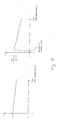
- the maximum Doppler frequency contained in the received data signal is smaller than the smaller of the two values f dmax1 and f dmax2 .
- a preferred embodiment of the method according to the invention also provides that the measure Q for the relative speed between transmitter 1 and receiver 2 is only determined if based on at least one in the formation of the predicted value s pred used parameters, in the present embodiment on the basis of the parameter c1, a temporal variance of the transmission channel is detected. In this way, unnecessary relative speed estimates can be avoided.
- a correction of the noise-impaired estimated value P v for the relative speed between the receiver 2 and the transmitter 1 is additionally carried out with the aid of the motion-compensated estimated value for the noise P noise .
- FIG. 3 shows a schematic illustration of an exemplary embodiment of a device according to the invention for motion-compensated noise estimation.
- This has memory devices 20a, 20b,..., 20L for reference symbols which can be supplied from a receiver 2 and which are transmitted in time or in the middle directly or successively by the transmitter 1 s 1 , s -2 , ..., s -L on.
- These memory devices are advantageously designed as first-in-first-out memories (FIFO), so that the last L reference symbols are always available in the memory devices.
- FIFO first-in-first-out memories
- a static fraction s avg of the received reference symbols s -1 , s -2 , s -L by forming a statistical moment from at least part of the reference symbols stored in the storage devices 20a, 20b, ..., 20L s -1 , s -2 , ..., s L , a corresponding device 22 is provided.
- the calculation of the statistical moment takes place by forming the arithmetic mean value of all reference symbols stored in the memory devices 20a, 20b,..., 20L s -1 , s -2 , ..., s -L .
- a subtractor 24 is provided. This is the reference symbol stored in the storage device 20a s -1 and the reference symbol s be supplied, wherein in the embodiment variant shown in Figure 3 for ⁇ , the value 4 was selected so that as s - ⁇ the reference symbol stored in the memory device 20d s -4 is the subtractor 24 can be fed.
- a predictor 30 for determining a prediction value s pred for the next reference symbol supplied by the receiver s 0 with the help of the static part s avg and dynamic share s motion of the reference symbols s -1 , s - 2 , ... s -L provided.
- the determined static share s avg and the dynamic portion formed in the subtractor s motion can be fed to this predictive device.
- the predictive value s pred and the next reference symbol supplied by the receiver s 0 are each a subtractor 26 can be fed.
- This subtracter 26 serves as a means for determining a prediction error s err from the difference between the predicted reference symbol s pred and the next reference symbol supplied by the receiver s 0 .
- a squares unit 28 and an averaging unit 27 are provided as means for calculating an estimated value P noise for the noise of a data signal transmitted in a transmission channel 5 from the prediction error s err .
- the prediction error s err can be supplied to the unit for forming squares of sums 28; the value determined here can furthermore be supplied to the averaging unit 27. From the averaging unit 27, an estimated value for the noise P noise can be output.
- means for adapting the predictor 30 are based on the prediction error s err on temporal changes of the transmission channel 5 is provided.
- the determination of a predicted value takes place s pred by forming a linear combination of the static component s avg and the dynamic share s motion using parameters c0 and c1.
- a unit for adjusting c0 32 and a unit for adjusting c1 33 are arranged in FIG.
- other formation of the predictive value s pred are accordingly provide other means for adapting the prediction device 30th
- in the unit for adapting c0 means for complex conjugation of the static moment are provided s avg and the multiplication of the result with the prediction error , as well as means for forming the real part of the resulting product. Furthermore, a means for multiplying the real part by a scaling factor for step size regulation sz 0 is provided, resulting in an adaptation step for c0.
- an intended multiplexer MUX is decidable whether c0 is subjected to this adaptation step, or by using a unit for averaging of adaptation steps 35 first performs an averaging of several adaptation steps and c0 is adjusted based on the result.
- the unit for adaptation of c1 has an analog structure, but instead of the means for multiplying the real part by the scaling factor sz 0 , a means is provided for multiplying the real part by the scaling factor for step size control sz 1 , and instead of c0 c1 is subject to the resulting adaptation steps or the adjustment on the basis of the adjustment value determined by the unit for averaging c1 adjustment steps.
- FIGS. 35 and 36 illustrate a development of the invention Device is because with their help too high sensitivity the device for motion-compensated noise estimation is avoidable over short-term disturbances.
- the relative speed estimation unit 50 represents such a means. With its aid, in addition to the motion-compensated noise estimation, an estimate of the relative velocity P v between transmitter 1 and receiver 2 can be made.
- the relative speed estimation unit 50 has a subtracter 52, which has the reference symbol s -1 , as well as the reference symbol s - ⁇ , where ⁇ is chosen here as 5, can be supplied from the corresponding storage devices 20a and 20e.
- the difference determined by the subtracter 52 can be supplied to the unit for forming squares sums 54, the reference symbol s -1 is also the unit for forming squares of sums 53 fed.
- the output signals of the units for the formation of absolute squares 53 and 54 can be supplied to summers 56 and 57, respectively, in which an energy measure s energy or a speed measure s diff can be determined. From the energy measure s energy and the speed measure s diff , a measure Q for the relative speed can be determined, from which an estimated value P v for the relative speed between transmitter 1 and receiver 2 can be determined.
- ⁇ ⁇ is selected and the output signal of the subtractor 24 s motion in addition to the prediction device 30 and the relative speed estimation unit 50 or the unit for the formation of magnitude squares 54 can be supplied, so that the subtractor 52 can be dispensed with.
- the various units, devices, subtractors and summers as well as storage devices all or in part in one or multiple microprocessor units integrated.
- an embodiment variant of the invention provides that the time interval T, in which reference symbols 14, 16 are sent and / or the shape of the reference symbols in the device according to the invention can be stored.
Landscapes
- Engineering & Computer Science (AREA)
- Computer Networks & Wireless Communication (AREA)
- Signal Processing (AREA)
- Quality & Reliability (AREA)
- Noise Elimination (AREA)
- Mobile Radio Communication Systems (AREA)
Abstract
Description
- Figur 1
- bereits behandelte schematische Darstellung eines mobilen drahtlosen Übertragungssystems nach dem Stand der Technik.
- Figur 2
- Beispiele für Datensignale mit eingefügten Referenzsymbolen nach dem Stand der Technik, wobei in (a) das Datensignal eine Trägerfrequenz aufweist, in (b) ein OFDM-Datensignal dargestellt ist.
- Figur 3
- Schematische Darstellung einer erfindungsgemäßen Vorrichtung zur bewegungskompensierten Rauschschätzung.
| Statischer Übertragungskanal | c0 ≈ 1 | c1 ≈ 0 |
| Zeitvarianter Übertragungskanal | c0 ≈ 1 | |

| 1 | Sender |
| 2 | Empfänger |
| 3 | Hindernis |
| 5 | Übertragungskanal |
| 10 | Datensignal |
| 11 | OFDM-Datensignal |
| 12 | Informationssymbol |
| 14 | gespeichertes Referenzsymbol |
| 16 | neues Referenzsymbol |
| 18 | neues OFDM-Symbol |
| 20a | Speichervorrichtung |
| 20b | Speichervorrichtung |
| 20c | Speichervorrichtung |
| 20d | Speichervorrichtung |
| 20e | Speichervorrichtung |
| 20f | Speichervorrichtung |
| 20L | Speichervorrichtung |
| 22 | Einrichtung zur Berechnung des statistischen Moments |
| 24 | Subtrahierer |
| 26 | Subtrahierer |
| 27 | Mittelungseinheit |
| 28 | Einheit zur Bildung von Betragsquadraten |
| 30 | Vorhersageeinrichtung |
| 32 | Einheit zur Anpassung von c0 |
| 33 | Einheit zur Anpassung von c1 |
| 35 | Einheit zur Mittelung von c0-Anpassungschritten |
| 36 | Einheit zur Mittelung von c1-Anpassungschritten |
| 50 | Relativgeschwindigkeitschätzeinheit |
| 52 | Subtrahierer |
| 53 | Einheit zur Bildung von Betragsquadraten |
| 54 | Einheit zur Bildung von Betragsquadraten |
| 56 | Summierer |
| 57 | Summierer |
|
|
empfangenes Referenzsymbol |
|
|
empfangenes Referenzsymbol |
|
|
empfangenes Referenzsymbol |
|
|
empfangenes Referenzsymbol |
|
|
empfangenes Referenzsymbol |
|
|
empfangenes Referenzsymbol |
|
|
empfangenes Referenzsymbol |
|
|
statischer Anteil der empfangenen Referenzsymbole |
|
|
dynamischer Anteil der empfangenen Referenzsymbole |
|
|
Vorhersagefehler |
|
|
Vorhersagewert |
|
|
Energiemaß |
|
|
Geschwindigkeitsmaß |
| T | zeitlicher Abstand der Referenzsymbole |
| k | Laufindex |
| f0 | Trägerfrequenz |
| f1 | Trägerfrequenz |
| f2 | Trägerfrequenz |
| f3 | Trägerfrequenz |
| f4 | Trägerfrequenz |
| f5 | Trägerfrequenz |
| f6 | Trägerfrequenz |
| f | Frequenzachse |
| Pnoise | Schätzwert Rauschen |
| Pv | Schätzwert Relativgeschwindigkeit zwischen Sender und Empfänger |
| fdmax2 | maximale Dopplerfrequenz im empfangenen Datensignal |
| fdmax1 | maximale Dopplerfrequenz im empfangenen Datensignal |
| fg | Grenzfrequenz |
| Q | Maß für Relativgeschwindigkeit |
|
|
neu empfangenes Referenzsymbol |
Claims (18)
- Verfahren zur bewegungskompensierten Rauschschätzung bei mobilen drahtlosen Übertragungssystemen, bei welchen von einem Sender (1) Referenzsymbole (14, 16) ausgesandt werden mit folgenden Merkmalen:dass aus wenigstens einem Teil zeitlich mittel- oder unmittelbar aufeinanderfolgend in einem Empfänger (2) empfangener Referenzsymbole (
s - 1 ,s -2 ,s -3) durch Bildung eines statistischen Moments ein statischer Anteil (s avg ) der empfangenen Referenzsymbole (s -1,s -2 ,s -3) ermittelt wird;dass ein dynamischer Anteil (s motion ) der empfangenen Referenzsymbole (s -1 ,s -2 ,s -3 ) durch Vergleich mindestens zweier mittel- oder unmittelbar zeitlich aufeinanderfolgender Referenzsymbole (s -µs -1 ) ermittelt wird;dass aus dem statischen (s avg ) und dem dynamischen Anteil (s motion ) der empfangenen Referenzsymbole (s -1 ,s -2 ,s -3 ) ein Vorhersagewert (s pred ) für das nächste empfangene Referenzsymbol (s 0) berechnet wird;dass nach Empfang des nächsten Referenzsymbols (so) durch Vergleich dieses empfangenen Referenzsymbols (so) mit dem Vorhersagewert (s pred ) ein Vorhersagefehler (s err ) bestimmt wird;dass aus dem Vorhersagefehler (s err ) ein Schätzwert für das Rauschen (Pnoise) eines in einem Übertragungskanal (5) übertragenen Datensignals ermittelt wird;dass unter Berücksichtigung des Vorhersagefehlers (s err ) die Berechnung des Vorhersagewertes (s pred ) an zeitliche Veränderungen des Übertragungskanals angepasst wird. - Verfahren nach Anspruch 1,
dadurch gekennzeichnet, dass für die Auswertung der Referenzsymbole (s -1,s -2,s -3) ein im Empfänger (2) bekannter zeitlicher Abstand (T), in welchem die Referenzsymbole (s -1 ,s -2 ,s -3 ) ausgesandt werden, und/oder eine im Empfänger (2) bekannte Gestalt der Referenzsymbole (s -1,s -2,s -3) herangezogen werden. - Verfahren nach einem der Ansprüche 1 bis 2,
dadurch gekennzeichnet, dass die Referenzsymbole (s -1 ,s -2 ,s -3 ) in gleichen Zeitabständen (T) ausgesandt werden. - Verfahren nach einem der Ansprüche 1 bis 3,
dadurch gekennzeichnet, dass zur Berechnung des Vorhersagewertes (s pred ) eine Linearkombination aus dem statischen (s avg) und dem dynamischen Anteil (s motion) der Referenzsymbole (s -1,s -2,s -3) verwendet wird. - Verfahren nach einem der Ansprüche 1 bis 4,
dadurch gekennzeichnet, dass die Berechnung des Vorhersagewertes (s pred ) unter Verwendung der Methode der kleinsten Fehlerquadrate an zeitliche Veränderungen des Übertragungskanals (5) angepasst wird. - Verfahren nach einem der Ansprüche 1 bis 5,
dadurch gekennzeichnet, dass die Berechnung des Vorhersagewertes (s pred ) jeweils nach der Ermittlung eines weiteren Vorhersagefehlers (s pred ) angepasst wird. - Verfahren nach einem der Ansprüche 1 bis 5,
dadurch gekennzeichnet, dass die Anpassung der Berechnung des Vorhersagewertes (s pred ) stets nach bestimmten Zeitintervallen erfolgt, wobei wenigstens ein Teil der im jeweiligen Zeitintervall ermittelten Vorhersagefehler (s pred ) berücksichtigt wird. - Verfahren nach Anspruch 7,
dadurch gekennzeichnet, dass die Anpassung der Berechnung des Vorhersagewertes (s pred ) durch Mittelung der jeweils aus der Berücksichtigung der einzelnen Vorhersagefehler (s err ) resultierenden Anpassungen erfolgt. - Verfahren nach einem der Ansprüche 1 bis 8,
dadurch gekennzeichnet, dass der Wert mindestens eines bei der Berechnung des Vorhersagewertes (s pred ) eingesetzten Parameters (c1) als Indikator für die zeitliche Varianz des Übertragungskanals (5) verwendet wird. - Verfahren nach einem der Ansprüche 1 bis 9,
dadurch gekennzeichnet, dass durch Summation der Betragsquadrate der Differenzen von K zeitlich jeweils gleich beabstandeten Referenzsymbolen (s -1 ,s -ξ ) und deren Normierung ein Maß Q für die zeitliche Änderung des Übertragungskanals (5) ermittelt wird, welchem ein Schätzwert Pv für die Relativgeschwindigkeit des Empfängers (2) zum Sender (1) zugeordnet wird, wobei Q insbesondere gemäß der Relationermittelt wird.
- Verfahren nach Anspruch 9 und 10,
dadurch gekennzeichnet, dass das Maß Q nur ermittelt wird, wenn anhand wenigstens eines bei der Berechnung des Vorhersagewertes (s pred ) verwendeten Parameters (c1) eine zeiliche Varianz des Übertragungskanals (5) festgestellt wird. - Vorrichtung zur bewegungskompensierten Rauschschätzung bei mobilen drahtlosen Übertragungssystemen, bei welchen von einem Sender Referenzsymbole ausgesandt werden, aufweisendSpeichervorrichtungen (20a, 20b, 20c) für aus einem Empfänger (2) zugeführte, zeitlich mittel- oder unmittelbar aufeinander folgend ausgesandte Referenzsymbole (
s -1 ,s -2 ,s -3 );Mittel (22) zur Berechnung eines statischen Anteils (s avg ) der empfangenen Referenzsymbole (s -1 ,s -2 ,s -3 ) durch Bildung eines statistischen Moments aus wenigstens einem Teil der in den Speichervorrichtungen (20a, 20b, 20c) gespeicherten Referenzsymbole (s -1,s -2,s -3);Mittel (24) zur Ermittlung eines dynamischen Anteils (s mo. tion) der empfangenen Referenzsymbole (s -1,s -2,s -3) aus der Differenz wenigstens zweier in den Speichervorrichtungen (20a, 20d) gespeicherter Referenzsymbole (s -1,s -µ) ;eine Vorhersageeinrichtung (30) zur Ermittlung eines Vorhersagewertes (s pred ) für das nächste vom Empfänger zugeführte Referenzsymbol (so) mit Hilfe des statischen Anteils (s avg ) und des dynamischen Anteils (s motion ) der Referenzsymbole (s -1,s -2,s -3) ;Mittel (26) zur Bestimmung eines Vorhersagefehlers (s err ) aus der Differenz zwischen dem vorhergesagten Referenzsymbol (s pred ) und dem nächsten vom Empfänger (2) zugeführten Referenzsymbol (s 0);Mittel (27, 28) zur Berechnung eines Schätzwertes (Pnoise) für das Rauschen eines in einem Übertragungskanal (5) übertragenen Datensignals aus dem Vorhersagefehler (s err );Mittel (32, 33) zur Anpassung der Vorhersageeinrichtung (30) anhand des Vorhersagefehlers (s err ) an zeitliche Veränderungen des Übertragungskanals. - Vorrichtung nach Anspruch 12,
dadurch gekennzeichnet, dass der zeitliche Abstand (T), in dem Referenzsymbole (14, 16) gesendet werden und/oder die Gestalt der Referenzsymbole (14, 16) in der Vorrichtung oder im Empfänger hinterlegbar ist. - Vorrichtung nach einem der Ansprüche 12 bis 13,
dadurch gekennzeichnet, dass in der Vorhersageeinrichtung (30) zur Vorhersage des nächsten vom Empfänger (2) zugeführten Referenzsymbols (so) die Bildung einer Linearkombination aus dem statischen (s avg ) und dem dynamischen Anteil (s motion ) der Referenzsymbole (s -1,s -2,s -3) vorgesehen ist. - Vorrichtung nach einem der Ansprüche 12 bis 14,
dadurch gekennzeichnet, dass Einheiten (35, 36) zur Ermittelung von Anpassungsschritten vorgesehen sind. - Vorrichtung nach einem der Ansprüche 12 bis 15,
dadurch gekennzeichnet, dass die Speichervorrichtungen (20a, 20b, 20c) für Referenzsymbole (s -1 ,s -2 ,s -3) als First-In-First-Out-Speicher ausgeführt sind. - Vorrichtung nach einem der Ansprüche 12 bis 16,
dadurch gekennzeichnet, dass Mittel (50) vorgesehen sind, mit denen anhand von in den Speichervorrichtungen (20a, 20b, 20c) für Referenzsymbole (s -1,s -2,s -3) gespeicherten Referenzsymbolen (s -ξ,s -1) die Relativgeschwindigkeit (Pv) zwischen Sender (1) und Empfänger (2) schätzbar ist. - Vorrichtung nach Anspruch 17,
dadurch gekennzeichnet, dass die Mittel (50) zur Ermittlung eines Schätzwertes (Pv) für die Relativgeschwindigkeit zwischen Sender (1) und Empfänger (2) mindestens zwei Summierer (56, 57) aufweisen.
Applications Claiming Priority (2)
| Application Number | Priority Date | Filing Date | Title |
|---|---|---|---|
| DE102004026072 | 2004-05-25 | ||
| DE102004026072A DE102004026072B4 (de) | 2004-05-25 | 2004-05-25 | Verfahren und Vorrichtung zur bewegungskompensierten Rauschschätzung bei mobilen drahtlosen Übertragungssystemen |
Publications (4)
| Publication Number | Publication Date |
|---|---|
| EP1601128A2 true EP1601128A2 (de) | 2005-11-30 |
| EP1601128A3 EP1601128A3 (de) | 2008-09-24 |
| EP1601128B1 EP1601128B1 (de) | 2009-12-02 |
| EP1601128B9 EP1601128B9 (de) | 2010-09-15 |
Family
ID=34935939
Family Applications (1)
| Application Number | Title | Priority Date | Filing Date |
|---|---|---|---|
| EP05009416A Expired - Lifetime EP1601128B9 (de) | 2004-05-25 | 2005-04-29 | Verfahren und Vorrichtung zur bewegungskompensierten Rauschschätzung bei mobilen drahtlosen Übertragungssystemen |
Country Status (4)
| Country | Link |
|---|---|
| US (1) | US7496165B2 (de) |
| EP (1) | EP1601128B9 (de) |
| CN (1) | CN1722712B (de) |
| DE (2) | DE102004026072B4 (de) |
Families Citing this family (3)
| Publication number | Priority date | Publication date | Assignee | Title |
|---|---|---|---|---|
| US8411765B2 (en) * | 2008-10-10 | 2013-04-02 | Ziva Corporation | Techniques and systems for wireless communications |
| EP2474102A4 (de) | 2009-09-03 | 2016-06-22 | Ziva Corp | Verfahren und systeme für auf zeitumkehrungsvorkodierungen beruhende kommunikationen |
| US8811546B2 (en) * | 2012-06-08 | 2014-08-19 | Rockwell Collins, Inc. | Adaptive reference symbol method and apparatus for a receiver |
Family Cites Families (14)
| Publication number | Priority date | Publication date | Assignee | Title |
|---|---|---|---|---|
| JPS57210785A (en) * | 1981-06-19 | 1982-12-24 | Kokusai Denshin Denwa Co Ltd <Kdd> | Adaptive forecasting system between frames of television signal |
| US4679086A (en) * | 1986-02-24 | 1987-07-07 | The United States Of America As Represented By The Secretary Of The Air Force | Motion sensitive frame integration |
| US5719630A (en) * | 1993-12-10 | 1998-02-17 | Nec Corporation | Apparatus for compressive coding in moving picture coding device |
| JP3426092B2 (ja) * | 1996-09-12 | 2003-07-14 | シャープ株式会社 | 動画像符号化装置における動き補償フレーム間予測方法 |
| US6208617B1 (en) * | 1998-02-27 | 2001-03-27 | Lucent Technologies, Inc. | Channel tracking in a mobile receiver |
| DE19923690A1 (de) * | 1999-05-22 | 2000-12-07 | Bosch Gmbh Robert | Verfahren zur Schätzung der relativen Geschwindigkeit eines Senders gegenüber einem Empfänger und Empfangsvorrichtung für Funksignale |
| US6184792B1 (en) * | 2000-04-19 | 2001-02-06 | George Privalov | Early fire detection method and apparatus |
| CN1114294C (zh) * | 2000-06-15 | 2003-07-09 | 华为技术有限公司 | 速度自适应信道估计方法及装置 |
| CN1110163C (zh) * | 2001-04-16 | 2003-05-28 | 华为技术有限公司 | 码分多址通信系统中平坦衰落信道的估计方法及其装置 |
| US6636574B2 (en) * | 2001-05-31 | 2003-10-21 | Motorola, Inc. | Doppler spread/velocity estimation in mobile wireless communication devices and methods therefor |
| US7106792B2 (en) | 2001-06-04 | 2006-09-12 | Qualcomm, Inc. | Method and apparatus for estimating the signal to interference-plus-noise ratio of a wireless channel |
| CN1156179C (zh) * | 2001-09-03 | 2004-06-30 | 信息产业部电信传输研究所 | 一种信道估计平均区间的动态调整方法和装置 |
| US6868271B2 (en) * | 2002-03-28 | 2005-03-15 | Nortel Networks Limited | Adaptive fast cell switching in cellular communications systems |
| US7042928B2 (en) * | 2002-10-23 | 2006-05-09 | Qualcomm Incorporated | Method and apparatus for pilot estimation using prediction error method |
-
2004
- 2004-05-25 DE DE102004026072A patent/DE102004026072B4/de not_active Expired - Fee Related
-
2005
- 2005-04-29 EP EP05009416A patent/EP1601128B9/de not_active Expired - Lifetime
- 2005-04-29 DE DE502005008607T patent/DE502005008607D1/de not_active Expired - Lifetime
- 2005-05-25 US US11/137,129 patent/US7496165B2/en not_active Expired - Fee Related
- 2005-05-25 CN CN200510072990.0A patent/CN1722712B/zh not_active Expired - Fee Related
Also Published As
| Publication number | Publication date |
|---|---|
| CN1722712B (zh) | 2011-01-26 |
| EP1601128B9 (de) | 2010-09-15 |
| DE502005008607D1 (de) | 2010-01-14 |
| US20050271171A1 (en) | 2005-12-08 |
| DE102004026072B4 (de) | 2007-02-15 |
| DE102004026072A1 (de) | 2005-12-29 |
| EP1601128A3 (de) | 2008-09-24 |
| EP1601128B1 (de) | 2009-12-02 |
| US7496165B2 (en) | 2009-02-24 |
| CN1722712A (zh) | 2006-01-18 |
Similar Documents
| Publication | Publication Date | Title |
|---|---|---|
| DE69728383T2 (de) | Verfahren und Apparat für Zeitsynchronisierung in einem Empfänger für ein Mehrträgersignal | |
| DE69933409T2 (de) | Verfahren un Anordnung zum Erreichen und Aufrechterhalten der Symbolsynchronisierung in einem OFDM-Übertragungssystem | |
| DE69025388T2 (de) | Gerät für Maximalwahrscheinlichkeitssequenzbewertung | |
| DE69325988T2 (de) | Verfahren zur schätzung der dichte der c/i (trägerstrom/interferenz) und der interferenzprobabilität im aufweg | |
| DE60029006T2 (de) | Verfahren und vorrichtung zum auswählen eines zeitschlitzes in einem tdma-signal | |
| DE102007023881A1 (de) | Verfahren und Vorrichtung zur Ermittlung einer unverkürzten Kanalimpulsantwort in einem OFDM-Übertragungssystem | |
| EP1601128B9 (de) | Verfahren und Vorrichtung zur bewegungskompensierten Rauschschätzung bei mobilen drahtlosen Übertragungssystemen | |
| DE60032906T2 (de) | Verfahren und Vorrichtung zur Kanalschätzung, insbesondere für ein Mobiltelefon | |
| EP1050143B1 (de) | Verfahren zur verarbeitung eines signals aus datensymbolen | |
| EP1316182B1 (de) | Verbesserte kanalentzerrung für mobilfunkempfänger | |
| EP4531479A1 (de) | Verbesserte prognose einer zielrate | |
| DE69732634T2 (de) | Verfahren zur bestimmung der qualität einer verbindung und empfänger | |
| EP3782868A2 (de) | Verfahren zur kalibrierung eines geschwindigkeitssensors eines schienenfahrzeugs | |
| WO2005050882A1 (de) | Verfahren und vorrichtung zur überwachung der trägerfrequenzstabilität von sendern in einem gleichwellennetz | |
| DE102009008321B4 (de) | Verfahren zur Entscheidung über die parallele Nutzung eines Kommunikationskanals eines Funknetzwerks sowie hierfür geeigneter Kommunikationsteilnehmer | |
| DE10230685B4 (de) | Verfahren zum Ermitteln der Signalqualität eines Mobilfunksignals | |
| EP0689983B1 (de) | Verfahren zum Ermitteln der Position einer bestimmten Achse eines Schienenfahrzeugs auf einem Gleisabschnitt | |
| DE4430348C2 (de) | Verfahren zum Trennen von Carrier-Signal und Interferer-Signal in einem Funksignal eines Mobilfunknetzes | |
| EP2700179A1 (de) | Verfahren zur kanalschätzung bei der fahrzeug-zu-umgebung-kommunikation und dazu eingerichtete kommunikationseinrichtung | |
| DE69909728T2 (de) | Verfahren zur Sendeleistungsregelung | |
| DE102008042172A1 (de) | Verfahren zum Betreiben eines Kommunikationssystems mit mehreren Knoten und Kommunikationssystem mit mehreren Knoten | |
| WO2016096605A1 (de) | Verfahren zum empfang von rundfunksignalen in einem empfangsgerät und empfangsgerät | |
| EP1071247B1 (de) | Kanalschätzung | |
| DE112013006939B4 (de) | Empfangsgerät und Empfangsverfahren | |
| DE102004036473B4 (de) | Verfahren und Vorrichtung zur Schätzung eines Frequenzversatzes und eines Frequenzgradienten einer Signalfolge |
Legal Events
| Date | Code | Title | Description |
|---|---|---|---|
| PUAI | Public reference made under article 153(3) epc to a published international application that has entered the european phase |
Free format text: ORIGINAL CODE: 0009012 |
|
| AK | Designated contracting states |
Kind code of ref document: A2 Designated state(s): AT BE BG CH CY CZ DE DK EE ES FI FR GB GR HU IE IS IT LI LT LU MC NL PL PT RO SE SI SK TR |
|
| AX | Request for extension of the european patent |
Extension state: AL BA HR LV MK YU |
|
| PUAL | Search report despatched |
Free format text: ORIGINAL CODE: 0009013 |
|
| AK | Designated contracting states |
Kind code of ref document: A3 Designated state(s): AT BE BG CH CY CZ DE DK EE ES FI FR GB GR HU IE IS IT LI LT LU MC NL PL PT RO SE SI SK TR |
|
| AX | Request for extension of the european patent |
Extension state: AL BA HR LV MK YU |
|
| RIC1 | Information provided on ipc code assigned before grant |
Ipc: H04L 27/26 20060101ALI20080820BHEP Ipc: H04L 1/20 20060101AFI20050928BHEP |
|
| 17P | Request for examination filed |
Effective date: 20090124 |
|
| AKX | Designation fees paid |
Designated state(s): DE FR GB IT NL |
|
| GRAP | Despatch of communication of intention to grant a patent |
Free format text: ORIGINAL CODE: EPIDOSNIGR1 |
|
| RAP1 | Party data changed (applicant data changed or rights of an application transferred) |
Owner name: TRIDENT MICROSYSTEMS (FAR EAST) LTD. |
|
| GRAS | Grant fee paid |
Free format text: ORIGINAL CODE: EPIDOSNIGR3 |
|
| GRAA | (expected) grant |
Free format text: ORIGINAL CODE: 0009210 |
|
| AK | Designated contracting states |
Kind code of ref document: B1 Designated state(s): DE FR GB IT NL |
|
| REG | Reference to a national code |
Ref country code: GB Ref legal event code: FG4D Free format text: NOT ENGLISH |
|
| REF | Corresponds to: |
Ref document number: 502005008607 Country of ref document: DE Date of ref document: 20100114 Kind code of ref document: P |
|
| REG | Reference to a national code |
Ref country code: NL Ref legal event code: VDEP Effective date: 20091202 |
|
| PG25 | Lapsed in a contracting state [announced via postgrant information from national office to epo] |
Ref country code: NL Free format text: LAPSE BECAUSE OF FAILURE TO SUBMIT A TRANSLATION OF THE DESCRIPTION OR TO PAY THE FEE WITHIN THE PRESCRIBED TIME-LIMIT Effective date: 20091202 |
|
| PGFP | Annual fee paid to national office [announced via postgrant information from national office to epo] |
Ref country code: FR Payment date: 20100506 Year of fee payment: 6 |
|
| PLBE | No opposition filed within time limit |
Free format text: ORIGINAL CODE: 0009261 |
|
| STAA | Information on the status of an ep patent application or granted ep patent |
Free format text: STATUS: NO OPPOSITION FILED WITHIN TIME LIMIT |
|
| 26N | No opposition filed |
Effective date: 20100903 |
|
| PG25 | Lapsed in a contracting state [announced via postgrant information from national office to epo] |
Ref country code: IT Free format text: LAPSE BECAUSE OF FAILURE TO SUBMIT A TRANSLATION OF THE DESCRIPTION OR TO PAY THE FEE WITHIN THE PRESCRIBED TIME-LIMIT Effective date: 20091202 |
|
| REG | Reference to a national code |
Ref country code: FR Ref legal event code: ST Effective date: 20111230 |
|
| PG25 | Lapsed in a contracting state [announced via postgrant information from national office to epo] |
Ref country code: FR Free format text: LAPSE BECAUSE OF NON-PAYMENT OF DUE FEES Effective date: 20110502 |
|
| REG | Reference to a national code |
Ref country code: DE Ref legal event code: R084 Ref document number: 502005008607 Country of ref document: DE Effective date: 20111202 Ref country code: DE Ref legal event code: R084 Ref document number: 502005008607 Country of ref document: DE Effective date: 20110426 |
|
| REG | Reference to a national code |
Ref country code: DE Ref legal event code: R082 Ref document number: 502005008607 Country of ref document: DE Representative=s name: EPPING HERMANN FISCHER, PATENTANWALTSGESELLSCH, DE |
|
| REG | Reference to a national code |
Ref country code: DE Ref legal event code: R082 Ref document number: 502005008607 Country of ref document: DE Representative=s name: EPPING HERMANN FISCHER, PATENTANWALTSGESELLSCH, DE Effective date: 20121023 Ref country code: DE Ref legal event code: R081 Ref document number: 502005008607 Country of ref document: DE Owner name: ENTROPIC COMMUNICATIONS, INC., US Free format text: FORMER OWNER: TRIDENT MICROSYSTEMS (FAR EAST) LTD., GRAND CAYMAN, KY Effective date: 20121023 Ref country code: DE Ref legal event code: R081 Ref document number: 502005008607 Country of ref document: DE Owner name: ENTROPIC COMMUNICATIONS, INC., SAN DIEGO, US Free format text: FORMER OWNER: TRIDENT MICROSYSTEMS (FAR EAST) LTD., GRAND CAYMAN, KY Effective date: 20121023 Ref country code: DE Ref legal event code: R082 Ref document number: 502005008607 Country of ref document: DE Representative=s name: EPPING HERMANN FISCHER PATENTANWALTSGESELLSCHA, DE Effective date: 20121023 |
|
| REG | Reference to a national code |
Ref country code: GB Ref legal event code: 732E Free format text: REGISTERED BETWEEN 20131107 AND 20131113 |
|
| PGFP | Annual fee paid to national office [announced via postgrant information from national office to epo] |
Ref country code: GB Payment date: 20150427 Year of fee payment: 11 |
|
| PGFP | Annual fee paid to national office [announced via postgrant information from national office to epo] |
Ref country code: DE Payment date: 20160427 Year of fee payment: 12 |
|
| GBPC | Gb: european patent ceased through non-payment of renewal fee |
Effective date: 20160429 |
|
| PG25 | Lapsed in a contracting state [announced via postgrant information from national office to epo] |
Ref country code: GB Free format text: LAPSE BECAUSE OF NON-PAYMENT OF DUE FEES Effective date: 20160429 |
|
| REG | Reference to a national code |
Ref country code: DE Ref legal event code: R119 Ref document number: 502005008607 Country of ref document: DE |
|
| PG25 | Lapsed in a contracting state [announced via postgrant information from national office to epo] |
Ref country code: DE Free format text: LAPSE BECAUSE OF NON-PAYMENT OF DUE FEES Effective date: 20171103 |