EP1601041A1 - Fuel cell - Google Patents
Fuel cell Download PDFInfo
- Publication number
- EP1601041A1 EP1601041A1 EP03780756A EP03780756A EP1601041A1 EP 1601041 A1 EP1601041 A1 EP 1601041A1 EP 03780756 A EP03780756 A EP 03780756A EP 03780756 A EP03780756 A EP 03780756A EP 1601041 A1 EP1601041 A1 EP 1601041A1
- Authority
- EP
- European Patent Office
- Prior art keywords
- fuel cell
- cell stack
- spring
- spring module
- stack according
- Prior art date
- Legal status (The legal status is an assumption and is not a legal conclusion. Google has not performed a legal analysis and makes no representation as to the accuracy of the status listed.)
- Granted
Links
Images




Classifications
-
- H—ELECTRICITY
- H01—ELECTRIC ELEMENTS
- H01M—PROCESSES OR MEANS, e.g. BATTERIES, FOR THE DIRECT CONVERSION OF CHEMICAL ENERGY INTO ELECTRICAL ENERGY
- H01M8/00—Fuel cells; Manufacture thereof
- H01M8/24—Grouping of fuel cells, e.g. stacking of fuel cells
- H01M8/2465—Details of groupings of fuel cells
- H01M8/247—Arrangements for tightening a stack, for accommodation of a stack in a tank or for assembling different tanks
-
- H—ELECTRICITY
- H01—ELECTRIC ELEMENTS
- H01M—PROCESSES OR MEANS, e.g. BATTERIES, FOR THE DIRECT CONVERSION OF CHEMICAL ENERGY INTO ELECTRICAL ENERGY
- H01M8/00—Fuel cells; Manufacture thereof
- H01M8/24—Grouping of fuel cells, e.g. stacking of fuel cells
-
- Y—GENERAL TAGGING OF NEW TECHNOLOGICAL DEVELOPMENTS; GENERAL TAGGING OF CROSS-SECTIONAL TECHNOLOGIES SPANNING OVER SEVERAL SECTIONS OF THE IPC; TECHNICAL SUBJECTS COVERED BY FORMER USPC CROSS-REFERENCE ART COLLECTIONS [XRACs] AND DIGESTS
- Y02—TECHNOLOGIES OR APPLICATIONS FOR MITIGATION OR ADAPTATION AGAINST CLIMATE CHANGE
- Y02E—REDUCTION OF GREENHOUSE GAS [GHG] EMISSIONS, RELATED TO ENERGY GENERATION, TRANSMISSION OR DISTRIBUTION
- Y02E60/00—Enabling technologies; Technologies with a potential or indirect contribution to GHG emissions mitigation
- Y02E60/30—Hydrogen technology
- Y02E60/50—Fuel cells
Definitions
- the present invention generally relates to a fuel cell stack. More particularly, the present invention relates to a fuel cell stack wherein a method for affording a fastening load to a fuel cell stack is improved.
- a fastening load of a fuel cell stack has to be uniform over an entire range of a transverse cross section of an electrode portion of a stack in order to decrease electrode contact resistance and seal gas and water. Moreover, the fastening load must not vary substantially.
- the fastening load of the fuel cell stack must be uniform over the entire range of the fuel cell surface.
- a temperature of the fuel cell may repeatedly change between an environmental temperature when operation is stopped (e.g., 20°C) and a temperature of cooling water during operation (about 80°C), and the fastening load of the fuel cell stack may change because of the fuel cell temperature changes.
- the fastening load of the fuel stack will also change because of a creep of an electrolyte membrane and electrodes after a long period of time.
- load changing factors must be absorbed and the fastening load of the fuel cell stack must not vary substantially.
- Japanese Patent Publication HEI 8-115737 discloses a fastening structure of a fuel cell stack where, in order to uniformly fasten the fuel cell stack, a single integral elastic resilient member is disposed at a central position between a first rigid fastening plate of a first size located at a first end of the fuel cell stack and a second rigid fastening plate of a second size smaller than the first size located at the first end of the fuel cell stack, and at four corners of the second fastening plate, the second fastening plate located at the first end of the fuel cell stack and the first fastening plate located at a second, opposite end of the fuel cell stack are fastened by a bolt and nut extending in a fuel cell piling direction.
- An object of the present invention is to address the aforementioned problems by providing a fuel cell stack which can follow not only inclination of an end surface of the pile of fuel cells, but also a change of a length of the pile of fuel cells in the fuel cell piling direction.
- Another object of the present invention is to address the aforementioned problems by providing a fuel cell stack which can make a fastening load uniform over an entire range of the fuel cell plane and can decrease alteration of the load in the fuel cell piling direction.
- the plurality of springs can be deformed independently of each other, the plurality of springs can follow not only an inclination of an end surface and a wavy deformation of the inclined end surface of the pile of fuel cells, but also a change of a length of the pile of fuel cells in the fuel cell piling direction.
- the fastening load is made uniform over an entire range of the fuel cell plane. Further, alteration of the load in the fuel cell piling direction can be decreased.
- the spherical seat member containing a load cell when compared with a structure such as that illustrated in FIG 20 wherein a layered assembly of a plurality of coned disk springs, a spherical seat member containing a load cell, and an adjust screw are disposed between an end plate and a pile of fuel cells, the spherical seat member containing a load cell and the layered assembly of a plurality of coned disk springs can be removed.
- the load loaded on the pile of fuel cells from the spring module can be made more uniform over the entire fuel cell surface, since the bottom wall of the casing can be deformed to be wavy, than in the case of Japanese Patent Publication HEI 8-115737 wherein the load is loaded on the pile of fuel cells from the rigid plate.
- the spring can follow the wavy, convex, and concave deformation of the end surface of the member which contacts the spring module plane-to-plane, so that a fastening load is made uniform over an entire range of the fuel cell surface.
- the end surface of the spring seat member is convexly curved by constructing the spring seat member from a ball, for example, even if a transverse load (a load directed in a direction perpendicular to the fuel cell piling direction) is loaded on the spring module from the member which contacts the spring module plane-to-plane, the spring seat can easily release the transverse load by rotating.
- the spring module is disposed at each of the opposite ends of the fuel cell stack in a fuel cell piling direction, when an impact load acts on the fuel cell stack and a first spring module located at a first end of the fuel cell stack is shrunk, a second spring module located at a second, opposite end of the fuel cell stack is temporarily expanded whereby the fastening load acting on the fuel cell stack is prevented from being temporarily decreased.
- the spring module since the spring module includes a shock absorber, even if an impact load acts on the fuel cell stack to operate to shrink the spring module, the shock absorber operates as if it were rigid against deformation of a high speed whereby the fastening load of the fuel cell stack is prevented from being temporarily loosened. Against deformation of a low speed such as a thermal deformation, the shock absorber can be deformed smoothly, generating little mechanical resistance.
- the spring module includes a plurality of types of resilient members having moduli of elasticity different from each other, even if the fastening load loaded on the pile of fuel cells by one type of resilient members is lost, the fastening load loaded on the pile of fuel cells is maintained by the other type of resilient members.
- one type of resilient members among the plurality of types of resilient members has a spring constant changing in magnitude corresponding to speed of deformation and a spring constant corresponding to a high speed of deformation is greater than a spring constant corresponding to a slow speed of deformation, the one type of resilient members becomes rigid against a high speed of deformation, whereby loss of a fastening load loaded on the fastened object (the pile of fuel cells) is prevented.
- the plurality of types of resilient members include a spring type and a low-resilience sponge type, the low-resilience sponge becomes rigid against a high speed of deformation, whereby loss of a fastening load on the biased object (the fuel cell) is prevented.
- the spring module since the spring module presents a load versus deformation characteristic bending at an intermediate deformation point in a full deformation range, the one type of resilient members becomes rigid against a high speed of deformation, whereby loss of a fastening load loaded on the fastened object (the pile of fuel cells) is prevented.
- the spring module since the spring module has a low spring constant and the spring module is precompressed or is used at a large deformation range, loss of a fastening load loaded on the fastened object (the pile of fuel cells) is prevented.
- the resilient member and the first and second members are made from corrosion-resistant materials, rust which will be generated affected by water drops caused by a change in temperature will be suppressed.
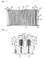
- FIGs. 1-3 are applicable to any embodiment of the present invention. Portions common to or similar throughout all embodiments of the present invention are denoted with the same reference numerals throughout all of the description and illustrations of the embodiments of the present invention.
- FIG 20 illustrates a comparison example which is not included within the scope of the present invention.
- a fuel cell 10 of a fuel cell stack of the present invention is of a low-temperature type, for example, a Polymer Electrolyte Fuel Cell (PEFC) type.
- the fuel cell 10 can be mounted to a vehicle, for example, but is not limited to use with a vehicle in any way.
- PEFC Polymer Electrolyte Fuel Cell
- the PEFC 10 includes a layer of a membrane-electrode assembly (MEA) and a separator 18.
- the MEA includes an electrolyte membrane 11 of an ion-exchange membrane, an electrode 14 (an anode, a fuel electrode) including a catalyst layer 12 disposed on one side of the membrane 11, and an electrode 17 (a cathode, an air electrode) including a catalyst layer 15 disposed on the other side of the membrane 11.
- Diffusion layers 13 and 16 may be disposed between the MEA and the separators on the anode side and the cathode side, respectively.
- a fuel gas passages 27 for supplying fuel gas (e.g., hydrogen) to the anode and an oxidant gas passage 28 for supplying oxidant gas (e.g., oxygen, usually, air) to the cathode are formed in the separators 18, and/or a coolant passage 26 for letting coolant (e.g., cooling water) flow is formed in the separators 18.
- At least one fuel cell 10 forms a fuel cell module 19.
- a plurality of fuel cell modules are piled in a fuel cell piling direction to form a pile of fuel cells and electrical terminals 20, electrical insulators 21, and end plates 22 are disposed at opposite ends of the pile of fuel cells.
- the end plates 22 are coupled to a fastening member (for example, a tension plate 24) extending in the fuel cell piling direction outside the pile of fuel cells by bolts 25 and/or nuts, thereby forming a fuel cell stack 23.
- the pile of fuel cells is tightened in the fuel cell piling direction.
- the fuel cell stack 23 may be directed in any direction, that is, it may be directed in a vertical direction or in a horizontal direction.
- the pile of fuel cells is restricted from side surfaces thereof by an outside restricting member 50 which is made from, for example, a sponge.
- each fuel cell 10 there occurs a reaction whereby hydrogen changes to hydrogen ions (i.e., protons) and electrons.
- the hydrogen ions move through the electrolyte membrane 11 to the cathode 17 where the hydrogen ions react with oxygen supplied and electrons (which are generated at an anode of an adjacent MEA and move to the cathode of the instant MEA through a separator 18) to form water as follows: At the anode: H 2 ⁇ 2H + + 2e - At the cathode: 2H + + 2e - + (1/2)O 2 ⁇ H 2 O
- the fuel cell stack 23 When the pile of fuel cells is tightened, the fuel cell stack 23 is given a fastening load to decrease an electrical contact resistance of the electrodes and to seal the reactant gas and coolant.
- the fastening load must be uniform over an entire range of a fuel cell plane and may not substantially change in magnitude even if the pile of fuel cells is shrunk or elongated in the fuel cell piling direction.
- a spring module 30 (which may be called as an elastically deformable module) is disposed in the fuel cell stack 23 including the pile of fuel cells so as to be in series with the pile of fuel cells in the fuel cell piling direction.
- the spring module 30 includes a first member 31 and a second member 32 which can be inclined relative to each other and may move in a direction toward and away from each other, and a plurality of springs 33 (resilient members) independent of each other which are arranged in parallel or in series with each other.
- the spring (resilient member) 33 may be a metal spring or a spring made from materials other than metal.
- the spring 33 may be a coil spring, a coned disk spring, or a member made from elastic material, for example, sponge, low-resilient sponge, rubber, elastic synthetic resin, etc.
- the plurality of springs 33 may comprise one type of springs or a plurality of types of springs.
- the plurality of springs 33 may have a common, single spring constant or a plurality of different spring constants.
- Each spring 33 can be a metal coil spring or a combination of a metal coil spring and a low-resilient sponge, for example, but the springs 33 are not limited to those examples in any way.
- the number of the springs 33 is preferably five or more, more preferably ten or more, and even more preferably about sixty per spring module.
- the spring module 30 can advantageously be made in the form of a unit (module) before the spring module 30 is mounted to the fuel cell stack 23. Therefore, the first member 31, the second member 32, and the springs 33 are handled and managed as a single unit (module) and are mounted to a predetermined position or predetermined positions of the fuel cell stack 23.
- the predetermined position or predetermined positions of the fuel cell stack 23 may be one end of the pile of fuel cells, opposite ends of the pile of fuel cells, or an intermediate position of the pile of fuel cell located between the opposite ends.
- the number of spring modules provided per fuel cell stack may be one, two, or more than two.
- walls perpendicular to the fuel cell piling direction, of the first member 31 and the second member 32 of the spring module 30 have a rigidity such that the walls are deformed so as to be convex and/or concave in the fuel cell piling direction and to be wavy when the walls receive loads from the plurality of springs 33 independent of each other.
- the walls perpendicular to the fuel cell piling direction, of the first member 31 and the second member 32 are not a rigid plate, but a deformable plate which can elastically be deformed to be convex and/or concave in the fuel cell piling direction and to be wavy.
- the spring module 30 is disposed between the end plate 22 located at one end of the fuel cell stack 23 and the pile of fuel cells. Between the spring module 30 and the end plate 22, a position adjust screw 34 is provided. Therefore, in a direction from the end plate 22 to the pile of fuel cells, the end plate 22, the adjust screw 34, a pressure plate 35, the spring module 30, the electrical insulator 21, the electrical terminal 20, and the pile of fuel cells are arranged in that order.
- the arrangement order of the spring module 30, the electrical insulator 21, the electrical terminal 20, and the pile of fuel cells may be instead ordered as the electrical insulator 21, the electrical terminal 20, the spring module 30, and the pile of fuel cells, or as the electrical insulator 21, the spring module 30, the electrical terminal 20, and the pile of fuel cells.
- the plurality of springs 33 can be deformed independently of each other and the first member 31 and the second member 32 of the spring module 30 are not a rigid plate, the plurality of springs 33 can follow not only an inclination of an end surface and a wavy deformation of the inclined end surface of the pile of fuel cells, but also a change of a length (a shrinkage or an expansion) of the pile of fuel cells in the fuel cell piling direction.
- the fastening load is made uniform over an entire range of the fuel cell plane. Further, alteration of the load in the fuel cell piling direction can be decreased.
- the structure including the end plate 22, the adjust screw 34, the spherical seat member 36, the load cell 37, the plurality of coned disk springs 38, and the pressure plate 35 follows an inclination of the end surface of the pile of fuel cells.
- the pressure plate 35 is a rigid plate, the pressure plate 35 cannot follow a wavy deformation of the end surface of the pile of fuel cells which is deformed to be convex and concave in the fuel cell piling direction, so that the pressure plate 35 cannot solve the problem of fluctuation of the load due to that wavy deformation.
- the fastening load is made uniform over an entire range of the fuel cell plane.
- the plurality of springs 33 are assembled in one unit (one module), it is easy to handle the spring module 30, to manage the load, and to mount the spring module 30 to the predetermined position of the fuel cell stack 23.
- the spherical seat member containing the load cell, and the adjust screw are disposed between the end plate and the pile of fuel cells
- the spherical seat member containing the load cell and the layered assembly of the plurality of coned disk springs can be removed.
- the spring module 30 since layering of the plurality of coned disk springs and managing of the load are conducted during assembly of the fuel cell stack, the work is difficult.
- the spring module 30 due to the spring module 30, it is possible to assemble the fuel cell stack and to manage the load before assembling the fuel cell stack, and the work is much easier than that of the comparison example.
- the fastening load can be more uniform over the entire range of the fuel cell plane. More particularly, when the number of the springs is about sixty, the fastening load becomes substantially uniform over the entire range of the fuel cell plane, and the bearing load of each spring 33 becomes small. As a result, a length of each spring 33 becomes short, and the spring module 30 becomes short in an axial direction and compact.
- the spring module 30 is disposed at the intermediate portion of the pile of fuel cells in a fuel cell piling direction, inclination and fluctuation of thickness of each fuel cell can be released at the intermediate portion of the pile of fuel cells before they are summed over the entire length of the pile of fuel cells.
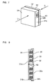
- the first member 31 is constructed from a first casing (since the first casing is the same member as the first member 31, a reference numeral of the first casing is selected to be 31), and the second member 32 is constructed from a second casing (since the second casing is the same member as the second member 32, a reference numeral of the second casing is selected to be 32).
- the spring module 30 is a casing assembly (configured in the form of a box) which houses the plurality of springs.
- the first casing 31 and the second casing 32 have bottom walls 31a and 32a parallel to the fuel cell plane and side walls 31b and 32b which extend toward the opposing casing 32 and 31 from outer peripheral portions of the bottom walls 31a and 32a.
- the springs 33 are disposed in a space enclosed by the first casing 31 and the second casing 32.
- Embodiment 1 is technically advantageous since the spring module 30 is formed in the form of a casing assembly, and the spring module 30 can thus be assembled in the fuel cell stack 23 by the form of a single assembly so that it is easy to mount the spring module 30 to the fuel cell stack 23. Further, since the load management is conducted at the spring module 30, the load management is easy compared with a case where each of the plurality of springs is managed.
- the walls perpendicular to the fuel cell piling direction (the bottom walls 31a and 32a) of the first casing 31 and the second casing 32 (especially, the bottom wall 31a of a casing 31 among the first and second casings 31 and 32 located closer to the pile of fuel cells) have such a rigidity that when the walls are pushed by the plurality of springs 33 independent of each other, the walls are deformed to be convex and/or concave in the fuel cell piling direction and are deformed in a form of a wave.
- the bottom walls are not a rigid plate but a plate elastically deformable in a wavy form by being deformed convex and/or concave in the fuel cell piling direction.
- Embodiment 2 is technically advantageous since when the flat plane perpendicular to the fuel cell piling direction, of the member contacting the spring module 30 is inclined from a plane perpendicular to the fuel cell piling direction, the first casing 31 and the second casing 32 are inclined relative to each other so that the spring module 30 can follow the inclination of the flat plane of the member contacting the spring module.
- the spring module 30 can follow the wavy deformation of the plane of the member contacting the spring module 30 by a wavy deformation of at least one of the bottom walls of the first and the second casings 31 and 32.
- the fastening load can be more uniform over the entire range of the fuel cell plane than in a case where a fastening load is loaded on the pile of fuel cells through a rigid plate.
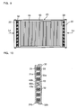
- the spring module 30 includes a plurality of spring seat members 39.
- the number of the spring seat members 39 is the same as that of the plurality of springs 33.
- Each of the plurality of spring seat members 39 has a first end portion (opposite a second end portion where the spring seat member 39 contacts the spring 33) which extends through an aperture 40 formed in the bottom wall 31a of the casing 31 among the first casing 31 and the second casing 32, located closer to the pile of fuel cells and contacts a member contacting the bottom wall 31a of the casing 31.
- Embodiment 3 is technically advantageous since the end portion of the spring seat member 39 extends through the aperture 40 formed in the bottom wall 31a of the casing 31, the spring 33 can thus follow the wavy, convex and concave deformation of the end surface of the member which plane-to-plane contacts the spring module 30 without being affected by the rigidity of the bottom wall 31a of the casing, so that the fastening load is made uniform over the entire range of the fuel cell plane.
- the spring module 30 includes a plurality of spring seat members 39.
- the number of the spring seat members 39 is the same as that of the plurality of springs 33.
- Each of the plurality of spring seat members 39 has a first end portion (opposite a second end portion where the spring seat member 39 contacts the spring 33) which extends through an aperture 40 formed in the bottom wall 31a of the casing 31 among the first casing 31 and the second casing 32, located closer to the pile of fuel cells and contacts a member contacting the bottom wall 31a of the casing 31.
- each spring seat member 39 has an end surface which is convexly curved.
- the spring seat member 39 is constructed from a ball so that the spring seat member 39 has a spherical end surface.
- Embodiment 4 is technically advantageous since the end portion of the spring seat member 39 extends through the aperture 40 formed in the bottom wall 31a of the casing 31, the spring 33 can thus follow the wavy, convex and concave deformation of the end surface of the member which plane-to-plane contacts the spring module 30 without being affected by the rigidity of the bottom wall 31a of the casing, so that the fastening load is made uniform over the entire range of the fuel cell plane.
- the end surface of the spring seat member 39 is convexly curved, for example, by constructing the spring seat member from a ball, even if a transverse load (a load directed in a direction perpendicular to the fuel cell piling direction) is loaded on the spring module from the member which contacts the spring module 30 plane-to-plane, the spring seat 39 can easily release the transverse load by its rotating. Furthermore, by constructing a protrusion protruding from the bottom wall of the casing by a ball, the spring seat member 39 can point-contact the member which contacts the spring module 30 plane-to-plane, so that an in-plane strain occurring in a plane-to-plane contact can be removed. As a result, the fastening load is made further uniform over the entire range of the fuel cell plane.
- the first casing 31 of the spring module 30 has a side wall 31b and the second casing 32 of the spring module 30 has a side wall 32b.
- a load expressing portion 41 is provided in the side walls 31b and 32b.
- the load expressing portion 41 is a mechanical load sensor.
- the mechanical load sensor includes a coil spring
- the load versus deformation characteristic is linear. Adjustment of load L is conducted beforehand.
- Embodiment 5 is technically advantageous since the load expressing portion 41 is provided in the side walls 31b and 32b of the casings 31 and 32, and it is thus unnecessary in the present invention to provide the load cell of the comparison example of FIG 20.
- the first member 31 for example, the first casing 31
- the second member 32 for example, the second casing 32
- an electrically conductive member 42 other than the plurality of springs 33.
- the spring module 30 may be disposed at an intermediate portion of the pile of fuel cells in a fuel cell piling direction in which the fuel cells are piled, or the spring module 30 may be disposed between the end surface of the pile of fuel cells and the electrical terminal 20.
- Embodiment 6 is technically advantageous since the first member 31 (for example, the first casing 31) and the second member 32 (for example, the second casing 32) are electrically connected to each other by the electrically conductive member 42 other than the plurality of springs 33, and the spring characteristic and the electrical conductivity are thus maintained respectively good. Due to this structure, even when the spring module 30 is disposed at an intermediate portion of the pile of fuel cells in a fuel cell piling direction in which the fuel cells are piled, or the spring module 30 is disposed between the end surface of the pile of fuel cells and the electrical terminal 20, no conductive problem occur.
- the spring module 30 is disposed at each of opposite ends of the fuel cell stack 23 in the fuel cell piling direction in which the fuel cells are piled (for example, inside the end plate 22 of the fuel cell stack).
- Embodiment 7 is technically advantageous since the spring module 30 is disposed at each of the opposite ends of the fuel cell stack 23 in the fuel cell piling direction, and thus when an impact load Ls temporarily acts on the fuel cell stack 23 and a first spring module 30 located at a first end of the fuel cell stack 23 is shrunk, a second spring module 30 located at a second, opposite end of the fuel cell stack 23 is temporarily expanded whereby the fastening load acting on the fuel cell stack 23 is prevented from being temporarily lost.
- the spring module 30 further includes a shock absorber 43 located between the first member 31 (the first casing 31) and the second member 32 (the second casing 32).
- the shock absorber 43 is located at a central portion of the first member 31 and the second member 32.
- the shock absorber 43 includes a cylinder 43a and a piston 43b where a small aperture 43c is formed.
- the cylinder 43a is filled with oil.
- Embodiment 8 is technically advantageous because when the piston 43b moves at a high speed, the resistance of the oil passing through the aperture 43c becomes large. As a result, when a shock load acts on the pile of fuel cells, the shock absorber 43 operates as if it were rigid and suppresses movement of the pile of fuel cells whereby the fastening load of the fuel cell stack is prevented from being temporarily lost. Contrarily, when the piston 43b moves at a low speed, the resistance of the oil passing through the aperture 43c becomes small. As a result, against a piston movement at a low speed such as a thermal expansion and shrinkage, the shock absorber 43 can be deformed without resistance, whereby the shock absorber 23 can follow the thermal expansion and shrinkage without loosening the fastening load of the fuel cell stack.
- the spring module 30 includes a plurality of shock absorbers 43, for example, the same number of shock absorbers 43 as the number of the springs 33. As illustrated in FIG. 11, each of the plurality of shock absorbers 43 and each of the plurality of springs 33 are coaxially arranged with each other.
- Embodiment 9 has the same technical advantages as those of embodiment 8.
- each shock absorber 43 can be disposed at the position of each spring 33, and a space required for disposing the springs 33 and the shock absorbers 43 therein can be minimized.
- the spring module 30 includes a plurality of types of resilient members 33a and 33b having moduli of elasticity different from each other.
- the number of resilient members of each type may be one, two or more.
- the plurality of types of resilient members 33a and 33b are disposed parallel to each other.
- one type of resilient members 33a among the plurality of types of resilient members 33a and 33b is a sponge of a low-resilience type
- the other type of resilient members 33b is a metal coil spring.
- the sponge 33a of a low-resilience type is called as a sponge of a slow recovery type.
- the sponge 33a of a low-resilience type has a spring constant changing in magnitude corresponding to speed of deformation where a spring constant corresponding to a high speed of deformation is greater than a spring constant corresponding to a slow speed of deformation.
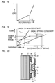
- FIG 13 illustrates a load versus deformation characteristic of the sponge 33a of a low-resilience type.
- the sponge 33a of a low-resilience type presents a characteristic of a high gradient where a load rises rapidly in a small deformation, for a deformation of a high speed which occurs at the time of a vehicle collision, to show a large and high spring constant.
- the sponge 33a of a low-resilience type presents a characteristic of a low gradient where a load rises slowly in a large deformation, to show a small and low spring constant.
- Embodiment 10 is technically advantageous since the spring module 30 includes a plurality of types of resilient members 33a and 33b having moduli of elasticity different from each other, so that even if the fastening load loaded on the pile of fuel cells by one type of resilient members 33a is lost, the fastening load loaded on the pile of fuel cells is maintained by the other type of resilient members 33b.
- the spring 33b is dominant.
- the sponge 33a bears the load, whereby the spring module can be prevented from being shrunk.
- the spring module is shrunk whereby the fastening load of the fuel cell stack will be lost or decreased temporarily.
- the spring module 30 houses the sponge 33a of a low-resilience type, the shrinkage of the spring module is prevented and the temporal loss of the fastening load is prevented.
- one type of resilient member 33a among the plurality of types of resilient members 33a and 33b holds the other type of resilient members 33b among the plurality of types of resilient members 33a and 33b.
- the one type of resilient member 33a is a sponge of a low-resilience type and the other type of resilient members 33b are a metal coil spring.
- the resilient member 33a of a low-resilience type is formed to be a single integral member, and in the single integral sponge 33a, the same number of holes 33c (each having a diameter equal to an outer diameter of the coil spring 33b) as the number of the coil springs 33b are formed. Each coil spring 33b is set in each hole 33.
- Embodiment 11 is technically advantageous since the one type of resilient member 33a holds the other type of resilient member 33b, and thus mounting the springs 33 to the casing of the spring module 30 and mounting the spring module 30 to the fuel cell stack 23 are easy tasks compared with a case where cut and bent portions are formed in a casing and springs are set to the cut and bent portions.
- the plurality of types of resilient members 33a and 33b are formed so as to be integral with each other.
- one type of resilient member 33a is a sponge of a low-resilience type and the other type of resilient members 33b are a metal coil spring.
- the coil springs 33b are embedded in the sponge 33a of a low-resilience type so as to be integral with the sponge 33a.
- Embodiment 12 is technically advantageous since the coil springs 33b are embedded in the sponge 33a of a low-resilience type so as to be integral with the sponge 33a, and thus mounting the integral assembly of the springs 33b and the sponge 33a to the casing of the spring module 30 and mounting the spring module 30 to the fuel cell stack 23 are easy tasks
- the sponge 33a can be inserted even into a space inside the spring 33b, the area where the sponge 33a is disposed can be increased. As a result, the effect due to the sponge 33a can be increased.
- the plurality of types of resilient members 33a and 33b are combined such that the spring module 30 presents a load versus deformation characteristic bending at an intermediate deformation point W 1 in a full deformation range W.
- one type of resilient member 33a and the other type of resilient member 33b are arranged in parallel with each other.
- a length H of the resilient member 33a in a free, not-compressed state is not equal to a space (H + H') between the first and second casings, and the length H is shorter than the space (H + H') by H'.
- the load is zero, there is a space of H' between the spring casing and the resilient member 33a.
- the resilient member 33a begins to receive a load.
- the load versus deformation characteristic is shown in FIG 18.
- the one type of resilient members 33a and the other type of resilient members 33b are combined such that up to a predetermined deformation of the spring module, the one type of resilient members 33b only are deformed, and above the predetermined deformation of the spring module, both types of resilient members 33a and 33b are deformed, whereby the load versus deformation characteristic of FIG. 18 is obtained.
- the spring module presents a low spring constant up to the predetermined deformation of the spring module, and presents a high spring constant above the predetermined deformation of the spring constant. According to a required characteristic, combination of the types of springs may be changed.
- a synthetic spring constant of the plurality of resilient members 33 of the spring module 30 is set to be low, and the spring module 30 is used in a precompressed state or at a large deformation range.
- the spring module is used at a use range B on line A of FIG 19.
- the spring module is used at a use range D on line C of FIG 19.
- Embodiment 14 is technically advantageous since, in the case where the spring module is precompressed, the temporal loss of the fastening load is prevented. Further, since the synthetic spring constant is set to be low, a large amount of dimensional fluctuations in the length of the pile of fuel cells can be absorbed in a predetermined load range.
- the resilient member 33 and the first and second members 31 and 32 are made from corrosion-resistant materials.
- the corrosion-resistant materials may include stainless steel and synthetic resin.
- Embodiment 15 is technically advantageous since the corrosion-resistance level is set high, so that a bad influence on the fuel cell by a rust such as iron oxide can be removed. Since the spring module 30 and the separator 18 spatially communicate with each other, iron oxide powder from the spring module may promote corrosion of the separator and metal ions may raise an electrical conductivity of the vicinity of the spring module. However, in the present invention, by suppressing generation of iron rust, the bad influence of the rust on the fuel cell can be removed.
- the fuel cell stack according to the present invention is useful as a fuel cell stack which can follow not only an inclination of the end surface of the pile of fuel cells, but also a change of the length of the pile of fuel cells in the fuel cell piling direction.
- the fuel cell stack according to the present invention is useful as a fuel cell stack which can make a fastening load uniform over an entire range of the fuel cell plane and can decrease alteration of the load in the fuel cell piling direction.
Landscapes
- Life Sciences & Earth Sciences (AREA)
- Engineering & Computer Science (AREA)
- Manufacturing & Machinery (AREA)
- Sustainable Development (AREA)
- Sustainable Energy (AREA)
- Chemical & Material Sciences (AREA)
- Chemical Kinetics & Catalysis (AREA)
- Electrochemistry (AREA)
- General Chemical & Material Sciences (AREA)
- Fuel Cell (AREA)
- Vibration Prevention Devices (AREA)
- Springs (AREA)
Abstract
Description
Claims (21)
- A fuel cell stack comprising:a pile of fuel cells; anda spring module disposed in series with said pile of fuel cells,said spring module including:a first member and a second member capable of inclining relative to each other and moving in a direction toward and away from each other; anda plurality of springs independent of each other and disposed in parallel with each other between said first member and said second member.
- A fuel cell stack according to claim 1, wherein said fuel cell stack includes an end plate and an adjust screw, said spring module being disposed between said end plate and said pile of fuel cells, and said adjust screw being disposed between said spring module and said end plate.
- A fuel cell stack according to claim 1, wherein said first member includes a first casing and said second member includes a second casing, said spring module including a casing assembly housing said plurality of springs.
- A fuel cell stack according to claim 3, wherein a casing among said first and second casings located closer to said pile of fuel cells includes a bottom wall having a rigidity such that when said wall is pushed by said plurality of springs independent of each other, said wall is deformed in a fuel cell piling direction in which said fuel cells are piled to be deformed in a form of a wave.
- A fuel cell stack according to claim 3, wherein said spring module includes a plurality of spring seat members, each of said plurality of spring seat members has an end portion which extends through an aperture formed in said wall of said casing located closer to said pile of fuel cells and contacts a member contacting said wall of said casing.
- A fuel cell stack according to claim 5, wherein said end portion of each of said plurality of spring seat members has an end surface which is convexly curved.
- A fuel cell stack according to claim 3, wherein said first and second casings of said spring module have a side wall where a load expressing portion is provided.
- A fuel cell stack according to any one of claims 1 and 3, wherein said spring module is disposed at an intermediate portion of said pile of fuel cells in a fuel cell piling direction in which said fuel cells are piled.
- A fuel cell stack according to claim 8, wherein said first member and said second member are electrically connected to each other by an electrically conductive member other than said plurality of springs.
- A fuel cell stack according to any one of claims 1 and 3, wherein said spring module is disposed at each of opposite ends of said fuel cell stack in a fuel cell piling direction in which said fuel cells are piled.
- A fuel cell stack according to any one of claims 1 and 3, wherein said spring module further includes a shock absorber located between said first member and said second member.
- A fuel cell stack according to any one of claims 1 and 3, wherein said spring module further includes a plurality of shock absorbers, each of said plurality of shock absorbers and each of said plurality of springs being coaxially arranged with each other.
- A fuel cell stack according to claim 1, wherein said spring module includes a plurality of types of resilient members having moduli of elasticity different from each other.
- A fuel cell stack according to claim 13, wherein said plurality of types of resilient members are disposed parallel to each other.
- A fuel cell stack according to claim 13, wherein one type of resilient members among said plurality of types of resilient members holds another type of resilient members among said plurality of types of resilient members.
- A fuel cell stack according to any one of claims 13 and 14, wherein said plurality of types of resilient members are formed so as to be integral with each other.
- A fuel cell stack according to claim 13, wherein one type of resilient members among said plurality of types of resilient members has a spring constant changing in magnitude corresponding to a speed of deformation where a spring constant corresponding to a high speed of deformation is greater than a spring constant corresponding to a slow speed of deformation.
- A fuel cell stack according to claim 13, wherein said plurality of types of resilient members include a spring and a sponge of a low-resilience type.
- A fuel cell stack according to claim 13, wherein said plurality of types of resilient members are combined such that said spring module presents a load versus deformation characteristic bending at an intermediate deformation point in a full deformation range.
- A fuel cell stack according to claim 13, wherein said spring module has a low spring constant, and said spring module is precompressed or is used at a large deformation range.
- A fuel cell stack according to claim 1, wherein said resilient member and said first and second members are made from corrosion-resistant materials.
Priority Applications (1)
| Application Number | Priority Date | Filing Date | Title |
|---|---|---|---|
| EP08166685A EP2169754A1 (en) | 2003-03-06 | 2003-12-15 | Fuel cell stack |
Applications Claiming Priority (5)
| Application Number | Priority Date | Filing Date | Title |
|---|---|---|---|
| JP2003059618 | 2003-03-06 | ||
| JP2003059618 | 2003-03-06 | ||
| JP2003390629A JP4639583B2 (en) | 2003-03-06 | 2003-11-20 | Fuel cell |
| JP2003390629 | 2003-11-20 | ||
| PCT/JP2003/016020 WO2004079850A1 (en) | 2003-03-06 | 2003-12-15 | Fuel cell |
Related Child Applications (1)
| Application Number | Title | Priority Date | Filing Date |
|---|---|---|---|
| EP08166685.1 Division-Into | 2008-10-15 |
Publications (3)
| Publication Number | Publication Date |
|---|---|
| EP1601041A1 true EP1601041A1 (en) | 2005-11-30 |
| EP1601041A4 EP1601041A4 (en) | 2008-05-28 |
| EP1601041B1 EP1601041B1 (en) | 2011-03-30 |
Family
ID=32964901
Family Applications (2)
| Application Number | Title | Priority Date | Filing Date |
|---|---|---|---|
| EP03780756A Expired - Lifetime EP1601041B1 (en) | 2003-03-06 | 2003-12-15 | Fuel cell |
| EP08166685A Withdrawn EP2169754A1 (en) | 2003-03-06 | 2003-12-15 | Fuel cell stack |
Family Applications After (1)
| Application Number | Title | Priority Date | Filing Date |
|---|---|---|---|
| EP08166685A Withdrawn EP2169754A1 (en) | 2003-03-06 | 2003-12-15 | Fuel cell stack |
Country Status (8)
| Country | Link |
|---|---|
| US (1) | US7833678B2 (en) |
| EP (2) | EP1601041B1 (en) |
| JP (1) | JP4639583B2 (en) |
| KR (2) | KR100745844B1 (en) |
| CN (2) | CN100385725C (en) |
| CA (1) | CA2516935C (en) |
| DE (1) | DE60336590D1 (en) |
| WO (1) | WO2004079850A1 (en) |
Cited By (9)
| Publication number | Priority date | Publication date | Assignee | Title |
|---|---|---|---|---|
| WO2007080472A3 (en) * | 2006-01-10 | 2007-12-13 | Toyota Motor Co Ltd | Fuel cell |
| EP2169754A1 (en) | 2003-03-06 | 2010-03-31 | Toyota Jidosha Kabushiki Kaisha | Fuel cell stack |
| WO2011098278A1 (en) * | 2010-02-15 | 2011-08-18 | Daimler Ag | Device for compressing a fuel cell arrangement by means of variable spring elements |
| US8541054B2 (en) | 2003-09-08 | 2013-09-24 | Honda Motor Co., Ltd | Methods for preparation of one-dimensional carbon nanostructures |
| WO2014072119A1 (en) * | 2012-11-08 | 2014-05-15 | Robert Bosch Gmbh | Battery module with two traction plates and two clamping plates |
| CN108615839A (en) * | 2018-05-04 | 2018-10-02 | 芜湖盛科环保技术有限公司 | A new energy vehicle battery module shock absorbing structure |
| CN109037517A (en) * | 2018-06-21 | 2018-12-18 | 杭州青杉奇勋科技有限公司 | A kind of battery fixing structure of the VR aircraft of antidetonation |
| US11342605B2 (en) | 2018-01-17 | 2022-05-24 | Toyota Jidosha Kabushiki Kaisha | Power storage device |
| EP3921887B1 (en) | 2019-02-07 | 2023-11-22 | EH Group Engineering AG | Fuel cell stack with compression means |
Families Citing this family (71)
| Publication number | Priority date | Publication date | Assignee | Title |
|---|---|---|---|---|
| JP4956890B2 (en) * | 2003-11-25 | 2012-06-20 | トヨタ自動車株式会社 | Fuel cell |
| CN100388548C (en) * | 2004-10-11 | 2008-05-14 | 上海神力科技有限公司 | An improved fuel cell stack pressing device |
| JP4696523B2 (en) * | 2004-10-15 | 2011-06-08 | トヨタ自動車株式会社 | Fuel cell |
| KR100709223B1 (en) * | 2005-11-09 | 2007-04-18 | 삼성에스디아이 주식회사 | Direct oxidation fuel cell |
| DE102005014077B4 (en) * | 2005-03-23 | 2012-05-24 | Forschungszentrum Jülich GmbH | Interconnector for high-temperature fuel cells and method for its production and method for operating a fuel cell |
| JP5109268B2 (en) * | 2006-03-06 | 2012-12-26 | トヨタ自動車株式会社 | Fuel cell and its elastic module |
| JP2008004307A (en) * | 2006-06-20 | 2008-01-10 | Toyota Motor Corp | Fuel cell |
| JP5045880B2 (en) | 2006-06-20 | 2012-10-10 | トヨタ自動車株式会社 | Fuel cell |
| JP5040043B2 (en) * | 2006-06-20 | 2012-10-03 | トヨタ自動車株式会社 | Fuel cell |
| JP5098493B2 (en) * | 2006-08-28 | 2012-12-12 | トヨタ自動車株式会社 | Assembly inspection system for fuel cells |
| JP5002219B2 (en) * | 2006-09-01 | 2012-08-15 | 中央発條株式会社 | Cell pressure assembly for fuel cell |
| DE102006060810B4 (en) * | 2006-12-21 | 2015-01-15 | Staxera Gmbh | Housing for receiving and clamping at least one fuel cell stack and fuel cell system |
| JP5181473B2 (en) * | 2006-12-27 | 2013-04-10 | トヨタ自動車株式会社 | Fuel cell |
| KR100784444B1 (en) * | 2006-12-29 | 2007-12-11 | 두산중공업 주식회사 | Stack pressure device |
| JP2008181812A (en) | 2007-01-25 | 2008-08-07 | Toyota Motor Corp | Fuel cell manufacturing apparatus and fuel cell |
| US7858259B2 (en) * | 2007-01-26 | 2010-12-28 | Topsoe Fuel Cell A/S | Fuel cell stack clamping structure and solid oxide fuel cell stack |
| JP5338065B2 (en) * | 2007-02-16 | 2013-11-13 | 日産自動車株式会社 | FUEL CELL, FUEL CELL ASSEMBLY METHOD AND ASSEMBLY DEVICE |
| DE102007012763B4 (en) * | 2007-03-16 | 2014-04-10 | Staxera Gmbh | Housing for receiving at least one fuel cell stack and fuel cell system with such a housing |
| US20110094892A1 (en) * | 2007-05-10 | 2011-04-28 | Zdenek Cerny | Electrolyser |
| CN101542815B (en) * | 2007-06-06 | 2011-11-16 | 松下电器产业株式会社 | Polymer electrolyte fuel cell |
| US7851102B2 (en) * | 2007-06-14 | 2010-12-14 | Gm Global Technology Operations, Inc. | Fuel cell stack compression retention system using overlapping sheets |
| US20090162726A1 (en) * | 2007-12-20 | 2009-06-25 | Kemal Ozgur | Compression apparatus for fuel cell stack |
| JP5200533B2 (en) * | 2007-12-28 | 2013-06-05 | トヨタ自動車株式会社 | Fuel cell unit and fuel cell |
| CA2659525A1 (en) * | 2008-03-25 | 2009-09-25 | Bdf Ip Holdings Ltd. | Fuel cell system with fuel cell stack receptacle |
| CN101577336B (en) * | 2008-05-07 | 2012-09-19 | 财团法人工业技术研究院 | End plate for battery system and battery system using the end plate |
| WO2010066464A1 (en) * | 2008-12-12 | 2010-06-17 | Ezelleron Gmbh | Fuel cell system with reoxidation barrier |
| JP4621815B2 (en) | 2009-03-17 | 2011-01-26 | パナソニック株式会社 | Fuel cell stack |
| DE102010006705B3 (en) * | 2010-02-02 | 2011-04-14 | Mtu Onsite Energy Gmbh | A fuel cell assembly |
| JP2011253730A (en) * | 2010-06-02 | 2011-12-15 | Toyota Motor Corp | Fuel cell stack |
| KR101106237B1 (en) * | 2010-07-30 | 2012-01-20 | 한국에너지기술연구원 | Fastening device of fuel cell stack |
| DE102010038681A1 (en) * | 2010-07-30 | 2012-02-02 | Bayerische Motoren Werke Aktiengesellschaft | Device for power supply with a cooling arrangement |
| KR101173870B1 (en) | 2010-08-18 | 2012-08-14 | 에스비리모티브 주식회사 | Battery module |
| JP5607561B2 (en) * | 2011-03-11 | 2014-10-15 | 日本特殊陶業株式会社 | Solid oxide fuel cell |
| US9029040B2 (en) * | 2012-04-17 | 2015-05-12 | Intelligent Energy Limited | Fuel cell stack and compression system therefor |
| KR101887704B1 (en) * | 2012-12-14 | 2018-08-10 | 현대자동차주식회사 | Fastning apparatus for fuel cell stack |
| US20150068416A1 (en) * | 2013-09-11 | 2015-03-12 | Hamilton Sundstrand Space Systems International, Inc. | Low profile laminate assemblies |
| JP5834059B2 (en) * | 2013-10-22 | 2015-12-16 | トヨタ自動車株式会社 | Fuel cell |
| JP5903564B2 (en) | 2013-12-13 | 2016-04-13 | パナソニックIpマネジメント株式会社 | Assembled battery |
| KR101579124B1 (en) * | 2013-12-30 | 2015-12-21 | 두산중공업 주식회사 | End plate for fuel cell stack |
| DE102014217425A1 (en) * | 2014-09-01 | 2016-03-03 | Robert Bosch Gmbh | Clamping device for battery cells and battery module, battery, battery system, vehicle and method for producing a battery module |
| JP6210049B2 (en) * | 2014-11-04 | 2017-10-11 | トヨタ自動車株式会社 | vehicle |
| DE112015005088B4 (en) | 2014-11-10 | 2023-09-21 | Kabushiki Kaisha Toyota Jidoshokki | BATTERY MODULE |
| KR101734622B1 (en) * | 2014-11-21 | 2017-05-11 | 현대자동차주식회사 | Combination structure of fuel cell stack |
| KR101806606B1 (en) | 2015-04-17 | 2017-12-07 | 현대자동차주식회사 | Structure for mounting fuel cell stack |
| JP6388004B2 (en) * | 2016-06-21 | 2018-09-12 | トヨタ自動車株式会社 | Fuel cell and fuel cell manufacturing method |
| CN105870487B (en) * | 2016-06-24 | 2019-01-01 | 苏州弗尔赛能源科技股份有限公司 | A kind of pem fuel cell stack steel band clamp device |
| KR102371046B1 (en) * | 2016-07-15 | 2022-03-07 | 현대자동차주식회사 | End cell heater for fuel cell |
| DE102016122442B4 (en) * | 2016-11-22 | 2025-12-24 | Audi Ag | Pressing device for pressing a fuel cell stack and fuel cell device with pressing device |
| JP6844400B2 (en) * | 2017-04-21 | 2021-03-17 | トヨタ自動車株式会社 | Fuel cell vehicle |
| CN110959203B (en) * | 2017-08-10 | 2022-09-13 | 松下知识产权经营株式会社 | Battery pack and method for manufacturing same |
| WO2019058902A1 (en) * | 2017-09-22 | 2019-03-28 | 日産自動車株式会社 | Spring member, fuel cell unit, fuel cell stack, and method for manufacturing fuel cell stack |
| JP2019128979A (en) * | 2018-01-19 | 2019-08-01 | トヨタ自動車株式会社 | Battery module |
| KR102506446B1 (en) | 2018-03-07 | 2023-03-06 | 삼성전자주식회사 | Battery housing structure and battery apparatus adopting the same |
| DE102018204363A1 (en) * | 2018-03-22 | 2019-09-26 | Audi Ag | Clamping system for fuel cell stack and fuel cell system with such |
| JP6637096B2 (en) * | 2018-03-27 | 2020-01-29 | 株式会社Subaru | Automotive battery |
| CA3107252A1 (en) * | 2018-03-30 | 2019-10-03 | Osaka Gas Co., Ltd. | Electrochemical module, method for assembling electrochemical module, electrochemical device, and energy system |
| CN108511648A (en) * | 2018-04-18 | 2018-09-07 | 中国石油大学(华东) | A kind of novel impact resistant power battery module |
| JP7224224B2 (en) * | 2019-03-29 | 2023-02-17 | 大阪瓦斯株式会社 | Electrochemical modules, electrochemical devices and energy systems |
| JP7169523B2 (en) * | 2019-04-02 | 2022-11-11 | トヨタ自動車株式会社 | assembled battery |
| DE102019219782A1 (en) | 2019-12-17 | 2021-06-17 | Robert Bosch Gmbh | Cell stack with at least one clamping device |
| CN113437427A (en) * | 2020-03-05 | 2021-09-24 | 奥迪股份公司 | Battery system and vehicle |
| JP7388708B2 (en) * | 2020-03-19 | 2023-11-29 | 株式会社アストム | Filter press type dialysis device and spring jig |
| EP3944385B1 (en) | 2020-07-23 | 2023-04-19 | AVL List GmbH | Removable load cell design for fuel cell stack |
| JP7272376B2 (en) | 2021-01-27 | 2023-05-12 | トヨタ自動車株式会社 | Load applying device and power storage device |
| CN115149062B (en) * | 2021-03-31 | 2025-06-03 | 未势能源科技有限公司 | Buffer and fuel cell stack |
| AT524562B1 (en) | 2021-08-13 | 2022-07-15 | H2i GreenHydrogen GmbH | Sealing device as a cell periphery for an electrolytic cell stack |
| US12315977B2 (en) * | 2021-11-01 | 2025-05-27 | GM Global Technology Operations LLC | Shock-force mitigation systems and methods for electrochemical fuel cell stacks |
| WO2024015392A1 (en) * | 2022-07-12 | 2024-01-18 | Paccar Inc | Battery pack enclosures for modular and scalable battery packs |
| CN115347223B (en) * | 2022-08-19 | 2025-01-21 | 东方电气(成都)氢燃料电池科技有限公司 | Compensation mechanism, stacked battery packaging structure and full-operating packaging force control method |
| KR102620799B1 (en) * | 2023-02-17 | 2024-01-05 | (주)넥슨스타 | Power vertically oriented water electrolysis stack |
| KR20250082850A (en) * | 2023-11-30 | 2025-06-09 | 삼성에스디아이 주식회사 | All-solid rechargeable battery |
Family Cites Families (33)
| Publication number | Priority date | Publication date | Assignee | Title |
|---|---|---|---|---|
| JPS58115772A (en) | 1981-12-26 | 1983-07-09 | Toshiba Corp | Fuel cell equipment |
| US4431714A (en) | 1982-07-01 | 1984-02-14 | The United States Of America As Represented By The United States Department Of Energy | Fuel cell design and assembly |
| JPS6139373A (en) | 1984-07-28 | 1986-02-25 | Fuji Electric Corp Res & Dev Ltd | Structure of cell stack assembly for fuel cell |
| JPS61248368A (en) * | 1985-04-25 | 1986-11-05 | Mitsubishi Electric Corp | Clamping device of layer-built type fuel cell |
| JPS6231942A (en) | 1985-08-02 | 1987-02-10 | Furukawa Electric Co Ltd:The | Stacked battery |
| JPH0624137B2 (en) | 1986-01-17 | 1994-03-30 | 株式会社日立製作所 | Fuel cell stack |
| US4689280A (en) | 1986-02-20 | 1987-08-25 | Energy Research Corporation | Fuel cell stack end plate structure |
| JP2566757B2 (en) * | 1986-05-19 | 1996-12-25 | ヤマハ発動機株式会社 | Fuel cell |
| JP2554126B2 (en) | 1988-04-15 | 1996-11-13 | 株式会社日立製作所 | Fuel cell stack |
| JP2943149B2 (en) | 1989-02-22 | 1999-08-30 | 三菱電機株式会社 | Molten carbonate fuel cell stack |
| US5686200A (en) | 1993-12-22 | 1997-11-11 | Ballard Power Systems Inc. | Electrochemical fuel cell assembly with compliant compression mechanism |
| US5547777A (en) | 1994-02-23 | 1996-08-20 | Richards Engineering | Fuel cell having uniform compressive stress distribution over active area |
| JPH0845535A (en) * | 1994-08-01 | 1996-02-16 | Ishikawajima Harima Heavy Ind Co Ltd | Fuel cell tightening device |
| JPH0888018A (en) | 1994-09-16 | 1996-04-02 | Toshiba Corp | Polymer electrolyte fuel cell |
| JPH08115737A (en) | 1994-10-17 | 1996-05-07 | Tanaka Kikinzoku Kogyo Kk | Cell stack fastening method for polymer electrolyte fuel cell |
| JP2860278B2 (en) * | 1995-10-16 | 1999-02-24 | 株式会社東芝 | Fuel cell |
| JPH09289027A (en) | 1996-04-24 | 1997-11-04 | Tanaka Kikinzoku Kogyo Kk | Carbon nonwoven fabric and stack structure for fuel cells |
| JPH1032015A (en) | 1996-07-17 | 1998-02-03 | Ishikawajima Harima Heavy Ind Co Ltd | Fuel cell tightening method |
| JP3815518B2 (en) | 1997-02-13 | 2006-08-30 | 石川島播磨重工業株式会社 | Molten carbonate fuel cell |
| JPH117975A (en) * | 1997-06-19 | 1999-01-12 | Yoyu Tansanengata Nenryo Denchi Hatsuden Syst Gijutsu Kenkyu Kumiai | Fastening control device for fuel cell |
| JPH1197054A (en) | 1997-09-22 | 1999-04-09 | Sanyo Electric Co Ltd | Fastening structure and method of layered body |
| US6884535B2 (en) | 1998-06-05 | 2005-04-26 | Nisshinbo Industries, Inc. | Fuel cell separator |
| US6210823B1 (en) * | 1998-08-19 | 2001-04-03 | Matsushita Electric Industrial Co. Ltd. | Polymer electrolyte fuel cell |
| JP3440843B2 (en) | 1998-10-02 | 2003-08-25 | 三菱電機株式会社 | Polymer electrolyte fuel cell and its system |
| JP3388710B2 (en) * | 1999-03-16 | 2003-03-24 | 三菱電機株式会社 | Fuel cell |
| US6613470B1 (en) | 1999-09-01 | 2003-09-02 | Honda Giken Kogyo Kabushiki Kaisha | Solid polymer electrolyte fuel cell stack |
| JP3956651B2 (en) * | 2000-08-07 | 2007-08-08 | トヨタ自動車株式会社 | Fuel cell |
| CA2353210C (en) * | 2000-07-19 | 2006-07-11 | Toyota Jidosha Kabushiki Kaisha | Fuel cell apparatus |
| JP4621370B2 (en) | 2001-02-28 | 2011-01-26 | 株式会社東芝 | Fuel cell stack structure |
| JP4672892B2 (en) | 2001-03-30 | 2011-04-20 | 本田技研工業株式会社 | Fuel cell stack |
| JP4227736B2 (en) * | 2001-04-04 | 2009-02-18 | 三菱重工業株式会社 | Solid polymer water electrolysis cell structure |
| JP3957294B2 (en) | 2003-02-04 | 2007-08-15 | 本田技研工業株式会社 | Fuel cell |
| JP4639583B2 (en) | 2003-03-06 | 2011-02-23 | トヨタ自動車株式会社 | Fuel cell |
-
2003
- 2003-11-20 JP JP2003390629A patent/JP4639583B2/en not_active Expired - Fee Related
- 2003-12-15 CA CA002516935A patent/CA2516935C/en not_active Expired - Lifetime
- 2003-12-15 EP EP03780756A patent/EP1601041B1/en not_active Expired - Lifetime
- 2003-12-15 CN CNB2003801100793A patent/CN100385725C/en not_active Expired - Fee Related
- 2003-12-15 EP EP08166685A patent/EP2169754A1/en not_active Withdrawn
- 2003-12-15 DE DE60336590T patent/DE60336590D1/en not_active Expired - Lifetime
- 2003-12-15 WO PCT/JP2003/016020 patent/WO2004079850A1/en not_active Ceased
- 2003-12-15 KR KR1020057016647A patent/KR100745844B1/en not_active Expired - Fee Related
- 2003-12-15 CN CNA2007101887845A patent/CN101174704A/en active Pending
- 2003-12-15 KR KR1020077010828A patent/KR100808622B1/en not_active Expired - Fee Related
-
2005
- 2005-08-19 US US11/206,839 patent/US7833678B2/en active Active
Cited By (11)
| Publication number | Priority date | Publication date | Assignee | Title |
|---|---|---|---|---|
| EP2169754A1 (en) | 2003-03-06 | 2010-03-31 | Toyota Jidosha Kabushiki Kaisha | Fuel cell stack |
| US7833678B2 (en) | 2003-03-06 | 2010-11-16 | Toyota Jidosha Kabushiki Kaisha | Fuel cell stack |
| US8541054B2 (en) | 2003-09-08 | 2013-09-24 | Honda Motor Co., Ltd | Methods for preparation of one-dimensional carbon nanostructures |
| WO2007080472A3 (en) * | 2006-01-10 | 2007-12-13 | Toyota Motor Co Ltd | Fuel cell |
| WO2011098278A1 (en) * | 2010-02-15 | 2011-08-18 | Daimler Ag | Device for compressing a fuel cell arrangement by means of variable spring elements |
| WO2014072119A1 (en) * | 2012-11-08 | 2014-05-15 | Robert Bosch Gmbh | Battery module with two traction plates and two clamping plates |
| US11342605B2 (en) | 2018-01-17 | 2022-05-24 | Toyota Jidosha Kabushiki Kaisha | Power storage device |
| CN108615839A (en) * | 2018-05-04 | 2018-10-02 | 芜湖盛科环保技术有限公司 | A new energy vehicle battery module shock absorbing structure |
| CN109037517A (en) * | 2018-06-21 | 2018-12-18 | 杭州青杉奇勋科技有限公司 | A kind of battery fixing structure of the VR aircraft of antidetonation |
| EP3921887B1 (en) | 2019-02-07 | 2023-11-22 | EH Group Engineering AG | Fuel cell stack with compression means |
| US12261340B2 (en) | 2019-02-07 | 2025-03-25 | Eh Group Engineering Ag | Fuel cell stack with compression means |
Also Published As
| Publication number | Publication date |
|---|---|
| EP2169754A1 (en) | 2010-03-31 |
| CN100385725C (en) | 2008-04-30 |
| KR20070052798A (en) | 2007-05-22 |
| KR100745844B1 (en) | 2007-08-02 |
| DE60336590D1 (en) | 2011-05-12 |
| KR100808622B1 (en) | 2008-02-29 |
| KR20050106092A (en) | 2005-11-08 |
| CA2516935C (en) | 2009-05-26 |
| EP1601041A4 (en) | 2008-05-28 |
| CA2516935A1 (en) | 2004-09-16 |
| US7833678B2 (en) | 2010-11-16 |
| CN1757132A (en) | 2006-04-05 |
| EP1601041B1 (en) | 2011-03-30 |
| WO2004079850A1 (en) | 2004-09-16 |
| JP4639583B2 (en) | 2011-02-23 |
| CN101174704A (en) | 2008-05-07 |
| US20050277012A1 (en) | 2005-12-15 |
| JP2004288618A (en) | 2004-10-14 |
Similar Documents
| Publication | Publication Date | Title |
|---|---|---|
| CA2516935C (en) | Fuel cell stack | |
| US8197984B2 (en) | Fuel cell stack | |
| CA2545132C (en) | Fuel cell stack | |
| US7070872B2 (en) | Fuel cell stack | |
| US7829241B2 (en) | Flexible bipolar plate | |
| JP4645092B2 (en) | Fuel cell device | |
| US20050158604A1 (en) | Fuel cell stack | |
| KR20050048275A (en) | A fuel cell module for electric vehicles | |
| KR100514375B1 (en) | A device for tightening stacks of fuel cell in electric vehicles | |
| US6991871B2 (en) | Fuel cell | |
| US7261964B2 (en) | Fuel cell stack housing | |
| WO2007080472A2 (en) | Fuel cell | |
| EP1965455B1 (en) | Sealing structure for fuel cell | |
| CN114079074B (en) | Fuel cell | |
| CN220692080U (en) | Insulating carrier | |
| JP2008053111A (en) | Fuel cell and vehicle equipped with the same | |
| WO2025204406A1 (en) | Fuel cell stack | |
| JP2003077501A (en) | Fuel cell holding device |
Legal Events
| Date | Code | Title | Description |
|---|---|---|---|
| PUAI | Public reference made under article 153(3) epc to a published international application that has entered the european phase |
Free format text: ORIGINAL CODE: 0009012 |
|
| 17P | Request for examination filed |
Effective date: 20050811 |
|
| AK | Designated contracting states |
Kind code of ref document: A1 Designated state(s): AT BE BG CH CY CZ DE DK EE ES FI FR GB GR HU IE IT LI LU MC NL PT RO SE SI SK TR |
|
| AX | Request for extension of the european patent |
Extension state: AL LT LV MK |
|
| DAX | Request for extension of the european patent (deleted) | ||
| RBV | Designated contracting states (corrected) |
Designated state(s): DE FR GB |
|
| A4 | Supplementary search report drawn up and despatched |
Effective date: 20080425 |
|
| 17Q | First examination report despatched |
Effective date: 20081009 |
|
| GRAP | Despatch of communication of intention to grant a patent |
Free format text: ORIGINAL CODE: EPIDOSNIGR1 |
|
| RIN1 | Information on inventor provided before grant (corrected) |
Inventor name: INAGAKI, TOSHIYUKI,C/O TOYOTA JIDOSHA KABUSHIKI KA |
|
| GRAS | Grant fee paid |
Free format text: ORIGINAL CODE: EPIDOSNIGR3 |
|
| GRAA | (expected) grant |
Free format text: ORIGINAL CODE: 0009210 |
|
| AK | Designated contracting states |
Kind code of ref document: B1 Designated state(s): DE FR GB |
|
| REG | Reference to a national code |
Ref country code: GB Ref legal event code: FG4D |
|
| REF | Corresponds to: |
Ref document number: 60336590 Country of ref document: DE Date of ref document: 20110512 Kind code of ref document: P |
|
| REG | Reference to a national code |
Ref country code: DE Ref legal event code: R096 Ref document number: 60336590 Country of ref document: DE Effective date: 20110512 |
|
| PLBE | No opposition filed within time limit |
Free format text: ORIGINAL CODE: 0009261 |
|
| STAA | Information on the status of an ep patent application or granted ep patent |
Free format text: STATUS: NO OPPOSITION FILED WITHIN TIME LIMIT |
|
| 26N | No opposition filed |
Effective date: 20120102 |
|
| REG | Reference to a national code |
Ref country code: DE Ref legal event code: R097 Ref document number: 60336590 Country of ref document: DE Effective date: 20120102 |
|
| REG | Reference to a national code |
Ref country code: GB Ref legal event code: 746 Effective date: 20120917 |
|
| REG | Reference to a national code |
Ref country code: DE Ref legal event code: R084 Ref document number: 60336590 Country of ref document: DE Effective date: 20120924 |
|
| REG | Reference to a national code |
Ref country code: FR Ref legal event code: PLFP Year of fee payment: 13 |
|
| REG | Reference to a national code |
Ref country code: FR Ref legal event code: PLFP Year of fee payment: 14 |
|
| REG | Reference to a national code |
Ref country code: FR Ref legal event code: PLFP Year of fee payment: 15 |
|
| PGFP | Annual fee paid to national office [announced via postgrant information from national office to epo] |
Ref country code: GB Payment date: 20211028 Year of fee payment: 19 Ref country code: FR Payment date: 20211109 Year of fee payment: 19 Ref country code: DE Payment date: 20211102 Year of fee payment: 19 |
|
| REG | Reference to a national code |
Ref country code: DE Ref legal event code: R119 Ref document number: 60336590 Country of ref document: DE |
|
| GBPC | Gb: european patent ceased through non-payment of renewal fee |
Effective date: 20221215 |
|
| PG25 | Lapsed in a contracting state [announced via postgrant information from national office to epo] |
Ref country code: GB Free format text: LAPSE BECAUSE OF NON-PAYMENT OF DUE FEES Effective date: 20221215 Ref country code: DE Free format text: LAPSE BECAUSE OF NON-PAYMENT OF DUE FEES Effective date: 20230701 |
|
| PG25 | Lapsed in a contracting state [announced via postgrant information from national office to epo] |
Ref country code: FR Free format text: LAPSE BECAUSE OF NON-PAYMENT OF DUE FEES Effective date: 20221231 |