JP4672892B2 - Fuel cell stack - Google Patents
Fuel cell stack Download PDFInfo
- Publication number
- JP4672892B2 JP4672892B2 JP2001099545A JP2001099545A JP4672892B2 JP 4672892 B2 JP4672892 B2 JP 4672892B2 JP 2001099545 A JP2001099545 A JP 2001099545A JP 2001099545 A JP2001099545 A JP 2001099545A JP 4672892 B2 JP4672892 B2 JP 4672892B2
- Authority
- JP
- Japan
- Prior art keywords
- cell stack
- fuel cell
- case
- plate
- gas
- Prior art date
- Legal status (The legal status is an assumption and is not a legal conclusion. Google has not performed a legal analysis and makes no representation as to the accuracy of the status listed.)
- Expired - Fee Related
Links
Images


Classifications
-
- H—ELECTRICITY
- H01—ELECTRIC ELEMENTS
- H01M—PROCESSES OR MEANS, e.g. BATTERIES, FOR THE DIRECT CONVERSION OF CHEMICAL ENERGY INTO ELECTRICAL ENERGY
- H01M8/00—Fuel cells; Manufacture thereof
- H01M8/24—Grouping of fuel cells, e.g. stacking of fuel cells
- H01M8/2465—Details of groupings of fuel cells
- H01M8/247—Arrangements for tightening a stack, for accommodation of a stack in a tank or for assembling different tanks
-
- H—ELECTRICITY
- H01—ELECTRIC ELEMENTS
- H01M—PROCESSES OR MEANS, e.g. BATTERIES, FOR THE DIRECT CONVERSION OF CHEMICAL ENERGY INTO ELECTRICAL ENERGY
- H01M2250/00—Fuel cells for particular applications; Specific features of fuel cell system
- H01M2250/20—Fuel cells in motive systems, e.g. vehicle, ship, plane
-
- Y—GENERAL TAGGING OF NEW TECHNOLOGICAL DEVELOPMENTS; GENERAL TAGGING OF CROSS-SECTIONAL TECHNOLOGIES SPANNING OVER SEVERAL SECTIONS OF THE IPC; TECHNICAL SUBJECTS COVERED BY FORMER USPC CROSS-REFERENCE ART COLLECTIONS [XRACs] AND DIGESTS
- Y02—TECHNOLOGIES OR APPLICATIONS FOR MITIGATION OR ADAPTATION AGAINST CLIMATE CHANGE
- Y02E—REDUCTION OF GREENHOUSE GAS [GHG] EMISSIONS, RELATED TO ENERGY GENERATION, TRANSMISSION OR DISTRIBUTION
- Y02E60/00—Enabling technologies; Technologies with a potential or indirect contribution to GHG emissions mitigation
- Y02E60/30—Hydrogen technology
- Y02E60/50—Fuel cells
-
- Y—GENERAL TAGGING OF NEW TECHNOLOGICAL DEVELOPMENTS; GENERAL TAGGING OF CROSS-SECTIONAL TECHNOLOGIES SPANNING OVER SEVERAL SECTIONS OF THE IPC; TECHNICAL SUBJECTS COVERED BY FORMER USPC CROSS-REFERENCE ART COLLECTIONS [XRACs] AND DIGESTS
- Y02—TECHNOLOGIES OR APPLICATIONS FOR MITIGATION OR ADAPTATION AGAINST CLIMATE CHANGE
- Y02T—CLIMATE CHANGE MITIGATION TECHNOLOGIES RELATED TO TRANSPORTATION
- Y02T90/00—Enabling technologies or technologies with a potential or indirect contribution to GHG emissions mitigation
- Y02T90/40—Application of hydrogen technology to transportation, e.g. using fuel cells
Landscapes
- Life Sciences & Earth Sciences (AREA)
- Engineering & Computer Science (AREA)
- Manufacturing & Machinery (AREA)
- Sustainable Development (AREA)
- Sustainable Energy (AREA)
- Chemical & Material Sciences (AREA)
- Chemical Kinetics & Catalysis (AREA)
- Electrochemistry (AREA)
- General Chemical & Material Sciences (AREA)
- Fuel Cell (AREA)
Description
【0001】
【発明の属する技術分野】
本発明は、燃料電池スタックに関し、一層詳細には、小型かつ軽量な燃料電池スタックに関する。
【0002】
【従来の技術】
一般的な燃料電池スタックの要部拡大断面図を図5に示す。この燃料電池スタック10は、複数個の単セル12が互いに電気的に直列接続されるとともに図5における左右方向に積層されてなるセルスタック13を備える。
【0003】
単セル12は、アノード側電極14とカソード側電極16との間に電解質層18が介装されることにより構成された接合体20と、該接合体20を挟持する1対のセパレータ22a、22bとを備える。両セパレータ22a、22bには、アノード側電極14に対向する面に該アノード側電極14に燃料ガス(例えば、水素を主成分とする水素含有ガス)を供給・排出するための第1ガス流路24が設けられる一方、カソード側電極16に対向する面に該カソード側電極16に酸化剤ガス(例えば、酸素を含有する酸素含有ガス)を供給・排出するための第2ガス流路26が設けられる。なお、接合体20は、額縁状シール部材30の開口部に収容保持されている。
【0004】
セルスタック13における両端に位置する単セル12、12には、集電用電極34a、34bがそれぞれ電気的に接続される。さらに、該集電用電極34a、34bの外側に漏電防止用の絶縁プレート36a、36bを介してエンドプレート38a、38bがそれぞれ配置され、各エンドプレート38a、38bの外側にバックアッププレート40a、40bがそれぞれ配置されることにより、燃料電池スタック10が構成される。なお、エンドプレート38aとバックアッププレート40aとの間には、複数個の皿ばね42が介装されている。
【0005】
以上の構成において、燃料電池スタック10の周縁部には、一方のバックアッププレート40aから他方のバックアッププレート40bに至るまで延在する複数個の貫通孔44が形成されている。図5および図6に示されるように、これら貫通孔44には各々タイロッド46が通されており、該タイロッド46にナット48(図5参照)が螺合されることにより両バックアッププレート40a、40bが締め付けられることに伴って、セルスタック13、集電用電極34a、34b、エンドプレート38a、38bが締め付け保持される。この際、皿ばね42が圧縮される。
【0006】
さらに、燃料電池スタック10の第1ガス入口通路62(図6参照)および第1ガス出口通路64には燃料ガス供給・排出機構が連結され、その一方で、第2ガス入口通路66および第2ガス出口通路68に酸化剤ガス供給・排出機構が連結される。また、冷却水入口通路70、冷却水出口通路71には、冷却水供給・排出機構がそれぞれ連結される。なお、図6中、参照符号74は、燃料電池スタック10を自動車車体に連結するボルト(連結部材)を通すべく図示しない貫通孔が設けられたマウント用ボス部を示す。
【0007】
このような燃料電池スタック10を運転するに際しては、該燃料電池スタック10に冷却水を流通させた状態でアノード側電極14に水素含有ガスが供給され、かつカソード側電極16に空気等の酸素含有ガスが供給される。水素含有ガス中の水素は、アノード側電極14において、以下の反応式(A)に示されるように電離し、その結果、水素イオンおよび電子が生成する。
【0008】
2H2→4H++4e …(A)
このうち、水素イオンは、電解質層18を介してカソード側電極16へ移動する。一方、電子は、アノード側電極14およびカソード側電極16に電気的に接続された外部回路に取り出され、該外部回路を付勢するための直流の電気エネルギとして利用される。
【0009】
その後、電子はカソード側電極16へと至り、該カソード側電極16に移動した水素イオンおよび該カソード側電極16に供給された酸素含有ガス中の酸素とともに以下の反応式(B)に示される反応を起こし、水を生成する。
【0010】
O2+4H++4e→2H2O …(B)
運転の最中、燃料電池スタック10が熱膨張を起こすと、その熱膨張量に応じて皿ばね42が圧縮または伸張する。このため、熱膨張後の燃料電池スタック10においても、セルスタック13に対する締め付け力が略均等な状態に維持される。
【0011】
【発明が解決しようとする課題】
ところで、上記のようにタイロッド46にてバックアッププレート40a、40b同士を締め付ける場合、燃料電池スタック10の外寸が大きくなってしまうという不具合がある。この理由は、燃料電池スタック10の周縁部にタイロッド46を通す貫通孔44を設けるための孔部形成代Sが必要となるからである(図6参照)。
【0012】
また、各タイロッド46の締め付け力は均等でなければならない。他の箇所に比して緩やかに締め付けられた箇所は、運転に際して燃料電池スタック10が熱膨張を起こしたときに締め付け力が低下することがあり、その結果、セルスタック13に接触不良が発生することに伴って内部抵抗が増加することによって燃料電池スタック10の発電特性が低下してしまうことがあるからである。このような事態を回避するために、バックアッププレート40a、40bとしては、タイロッド46による締め付け力が大きな場合においても撓みが生じないように厚肉なものが使用される。しかしながら、このこともまた燃料電池スタック10の外寸を大きくする一因となっている。バックアッププレート40a、40bが厚肉であるので、燃料電池スタック10における積層方向の寸法が大きくなるからである。この結果、必然的に燃料電池スタック10の重量も大きくなり、したがって、該燃料電池スタック10を搭載する自動車車体を走行させる際に大きな駆動力が必要になる。
【0013】
タイロッド以外で燃料電池スタックを保持する構造としては、特開平7−249426号公報、特開平7−335243号公報および特開平9−92324号公報に記載されているように、収容ケースもしくはスタック容器等に燃料電池スタックを収容することが知られている。また、特開2000−48850号公報には、2枚のプレッシャプレートの4方の隅角部同士を断面略L字型の保持部材によって連結することが提案されている。
【0014】
しかしながら、上記したいずれの場合においても、燃料電池スタックの小型化は図れるものの、単セルを均等な締め付け力で加圧することが困難であり、運転時に燃料電池スタックが熱膨張を起こした際に当該各燃料電池スタックの内部抵抗が増加する懸念があることが指摘されている。
【0015】
また、例えば、高剛性な収容ケースやスタック容器、あるいは保持部材に比してセルスタックの熱膨張量が大きい場合には、セルスタックの熱膨張が抑制されてしまうので該セルスタックに著しく大きな熱応力が作用することになる。このような状況下では、最終的に燃料電池スタックを構成する部材が変形してしまうことがあり、結局、セルスタックの接触不良、ひいては当該燃料電池スタックの内部抵抗の増加を招く懸念がある。
【0016】
本発明は上記した問題を解決するためになされたもので、小型かつ軽量で、かつ単セルの積層体を均等な締め付け力で加圧することが容易であり、しかも、構成部材同士の電気的な接触を良好に維持することが可能な燃料電池スタックを提供することを目的とする。
【0017】
【課題を解決するための手段】
前記の目的を達成するために、本発明は、燃料ガスが供給されるアノード側電極、酸化剤ガスが供給されるカソード側電極、および前記アノード側電極と前記カソード側電極との間に介装された電解質を有する接合体と、前記燃料ガスを供給するための燃料ガス供給路または前記酸化剤ガスを供給するための酸化剤ガス供給路が設けられて前記接合体を挟持する1対のセパレータとを備える単セルが所定数で互いに電気的に直列接続された積層体を具備するとともに、前記積層体の外側に集電用電極を介してエンドプレートがそれぞれ配設された燃料電池スタックであって、
前記積層体および前記集電用電極は、長手方向両端部が開口した開口端部であるケースに収容されており、
かつ前記ケースの一方および他方の前記開口端部に、前記エンドプレートを該ケースに連結する1組のヒンジ機構が設けられ、
前記1組のヒンジ機構は、前記積層体を均等な締め付け力で加圧するように対向して設けたタブ部を備えることを特徴とする。
【0018】
このような構成の燃料電池スタックにおいては、前記ケースおよび前記エンドプレートからの締め付けによって積層体が保持される。すなわち、タイロッドが不要となるので、タイロッドを通す貫通孔を設けるための孔部形成代も不要となる。しかも、この場合、バックアッププレートを使用する必要がなくなる上、エンドプレートとして薄肉のものを使用しても積層体を略均等な締め付け力で保持することができる。換言すれば、本発明においては、小型かつ薄肉のエンドプレートを用いるとともに、バックアッププレートを可及的に使用せずに燃料電池スタックを構成するようにしている。このため、燃料電池スタックを小型化かつ軽量化することができる。
【0019】
また、積層体がケースに収容されるので、組立作業者や他の物体が集電体またはセパレータ等に接触してしまうことがない。このため、組立作業者が感電することを回避することができる。
【0020】
さらに、燃料電池スタックの運転に際して当該燃料電池スタックが熱膨張を起こした場合においても、積層体に対する略均等な締め付け力を維持することができる。このため、例えば、セパレータと接合体等、燃料電池スタックを構成する部材同士の電気的な接触が良好に維持されるので、当該燃料電池スタックの内部抵抗が上昇して発電特性が低下することを回避することができる。
【0021】
さらにまた、前記ケースの少なくとも一端面が脱着可能であるので、該ケースに単セルを容易に収容することができる。
【0022】
その上、エンドプレートとケースとをヒンジ機構によって連結するようにしているので、燃料電池スタックが熱膨張を起こした際、エンドプレートはヒンジ機構を支点として中央部から容易に撓むことができる。すなわち、燃料電池スタックの熱膨張が妨げられることがない。したがって、燃料電池スタックに熱応力が作用することを抑制することができる。
【0023】
なお、前記ケースが金属材料からなる場合には、該ケースが前記集電用電極から離間するようにケースの寸法を設定すればよい。これにより、集電用電極からケースへと電流が流れること、すなわち、漏電を回避することができる。
【0024】
漏電を回避するためには、金属材料からなるケースの内表面に絶縁材料を被覆するようにしてもよい。
【0025】
上記したような燃料電池スタックは、例えば、自動車車体に搭載することができる。この場合、燃料電池スタックと自動車車体とを連結する連結部材を通すためのマウント用ボス部を前記エンドプレートに設けるようにすればよい。
【0026】
【発明の実施の形態】
以下、本発明に係る燃料電池スタックにつき好適な実施の形態を挙げ、添付の図面を参照して詳細に説明する。なお、図5および図6に示される構成要素と同一の構成要素には同一の参照符号を付し、場合によってはその詳細な説明を省略する。
【0027】
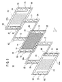
本実施の形態に係る燃料電池スタックの概略全体斜視図を図1に示す。この燃料電池スタック50は、複数個の単セル12が矢印A方向に積層されかつ互いに電気的に直列接続されてなるセルスタック13と、該セルスタック13における両端部に位置する単セル12、12の外側に集電用電極34a、34bを介してそれぞれ配設されたエンドプレート52a、52bと、セルスタック13を収容するためのケース54を備える。
【0028】
燃料電池スタック50の要部拡大断面図である図2に示されるように、単セル12は、アノード側電極14とカソード側電極16との間に電解質層18が介装されることにより構成された接合体20を備える。電解質層18としては、ポリテトラフルオロエチレンスルホン酸の薄膜に水を含浸させたもの等のような水素イオン導電体が選定される。
【0029】
アノード側電極14およびカソード側電極16は、カーボンクロス等からなるガス拡散層(図示せず)と、白金合金が表面に担持された多孔質カーボン粒子が前記ガス拡散層の表面に一様に塗布されてなる電極触媒層(図示せず)とをそれぞれ有し、電極触媒層同士が電解質層18を介して対向するように該電解質層18に接合されている。このうち、電解質層18は額縁状シール部材56の開口部に収容保持されており、一方、カソード側電極16またはアノード側電極14はガスケット58a、58bの開口部に収容保持されている。単セル12は、これらガスケット58a、58bと接合体20を保持する額縁状シール部材56とが1対のセパレータ60a、60bで挟持されることによって構成される。
【0030】
勿論、図3に示すように、これらセパレータ60a、60bにも第1ガス流路24および第2ガス流路26がそれぞれ設けられている。
【0031】
ここで、エンドプレート52a、セパレータ60a、60b、ガスケット58a、58bおよび額縁状シール部材56の各左上端部には水素含有ガスを通過させるための第1ガス入口通路62が設けられており、かつその対角位置には、未反応の水素含有ガスを通過させるための第1ガス出口通路64が設けられている(図1参照)。同様に、各右上端部には酸素含有ガスを通過させるための第2ガス入口通路66が設けられており、その対角位置には、未反応の酸素含有ガスを通過させるための第2ガス出口通路68が設けられている。勿論、第1ガス入口通路62および第1ガス出口通路64はいずれも第1ガス流路24に連通しており、一方、第2ガス入口通路66および第2ガス出口通路68はいずれも第2ガス流路26に連通している。
【0032】
エンドプレート52a、セパレータ60a、60b、ガスケット58a、58bおよび額縁状シール部材56には、さらに、第1ガス入口通路62と第2ガス出口通路68との間、および、第2ガス入口通路66と第1ガス出口通路64との間に、冷却水入口通路70、冷却水出口通路71がそれぞれ設けられている。
【0033】
セルスタック13の両端に位置する単セル12、12の外側に漏電防止用の絶縁プレート36a、36bを介して配置されるエンドプレート52a、52bの周縁部には、図1および図4に示すように、タブ部72a、72bが上下側面または左右側面にそれぞれ複数個突出形成されている。また、図1および図4における左右側面の下方には、マウント用ボス部74、74も突出形成されている。そして、これらタブ部72a、72bおよびマウント用ボス部74、74には、貫通孔75、76がそれぞれ形成されている(図1参照)。
【0034】
ここで、絶縁プレート36bとエンドプレート52bとの間には支持板77が介装されている。この支持板77における単セル12側の端面には、冷却水入口通路70、冷却水出口通路71に連通する冷却水ターン通路78が形成されており、また、エンドプレート52b側の端面には、図示しない複数本の支軸が固定されている。さらに、各々の支軸には皿ばね42が支持されている。
【0035】
ケース54は、底板80、第1側板82a、第2側板82bおよび天井板84からなり、これらはボルト86によって互いに締結される。すなわち、底板80の両側面の一部が鉛直上方に屈曲されることによって設けられた立ち上がり部88、88と、天井板84の両側面の一部が鉛直下方に屈曲されることによって設けられた垂下部90、90には、複数個のボルト穴92、92がそれぞれ設けられている。一方、第1側板82aおよび第2側板82bの両側面には段状縁部94、94が設けられており、各々の該段状縁部94、94には、立ち上がり部88、88および垂下部90、90の各ボルト穴92、92に対応する位置にボルト孔96、96がそれぞれ設けられている。各ボルト86はボルト孔96を通ってボルト穴92に螺合され、これによりケース54が構成される。すなわち、このケース54は互いに脱着可能な4枚の板80、82a、82bおよび84からなり、該ケース54の両端部は開口端である。
【0036】
なお、天井板84には、集電用電極34a、34bの端子部97、97を突出させるための切欠溝98、98が2箇所に設けられている。
【0037】
そして、底板80、第1側板82a、第2側板82bおよび天井板84の各両端部には、それぞれ、複数個のタブ部100a〜100cが突出形成されている。このうち、底板80または天井板84のタブ部100a、100cは、エンドプレート52a、52bの上下側面のタブ部72aに噛合する位置にそれぞれ形成されている(図4参照)。また、第1側板82aまたは第2側板82bのタブ部100bは、エンドプレート52a、52bの右左側面のタブ部72bおよびマウント用ボス部74に噛合する位置にそれぞれ形成されている。
【0038】
勿論、底板80、第1側板82a、第2側板82bおよび天井板84のタブ部100a〜100cにも貫通孔102が設けられており、したがって、図4に示す状態においては、タブ部72a、72bの貫通孔75とタブ部100a〜100cの貫通孔102とが互いに重ね合わせられる。
【0039】
互いに重ね合わされた貫通孔75、102には、ピン104(図1参照)がそれぞれ係合され、これによりヒンジ機構106が構成される。すなわち、エンドプレート52a、52bは、ヒンジ機構106によってケース54の両開口端部に連結される。この際、支持板77とエンドプレート52bとの間に介装された皿ばね42が圧縮され、したがって、エンドプレート52bは、皿ばね42によって単セル12の積層方向(矢印A方向)外方に指向して常時弾発付勢される。
【0040】
なお、皿ばね42および該皿ばね42を支持する前記支軸は、エンドプレート52bの一端面に設けられた凹部108に挿入される。
【0041】
このように、本実施の形態に係る燃料電池スタック50では、エンドプレート52a、52bおよびケース54にタブ部72a、72b、100a〜100cをそれぞれ設け、該タブ部72a、72b、100a〜100cの貫通孔75、102にピン104を通してヒンジ機構106を構成することによりエンドプレート52a、52bとケース54とを連結するようにしている。タブ部72a、72b、100a〜100cはエンドプレート52a、52bおよびケース54から僅かに突出させることにより設ければよく、したがって、エンドプレート52a、52bの外寸を、タイロッド46(図5参照)を通す貫通孔44を設けるための孔部形成代S(図6参照)を必要とするバックアッププレート40a、40bに比して著しく小さくすることができる。換言すれば、燃料電池スタック50を小型化することができるので、この燃料電池スタック50を自動車車体に搭載する際のスペースも狭小化することができる。
【0042】
しかも、エンドプレート52a、52bとケース54とがピン104で連結されるので、薄肉のエンドプレート52a、52bを使用する場合であっても、単セル12に対する締め付け力が略均等となる。また、エンドプレート52a、52bとして軽量なものを使用することができ、かつ従来技術に係る燃料電池スタック10のようにバックアッププレート40a、40bを使用する必要がない。
すなわち、燃料電池スタック50を軽量に構成することもできる。
【0043】
さらに、ケース54を互いに脱着可能な4枚の板80、82a、82bおよび84から構成するようにしたので、単セル12を該ケース54に容易に収容することができる。
【0044】
この場合、ケース54は金属材料から構成されているので、漏電を防止するために集電用電極34a、34bから所定間隔で離間して配置される。なお、エンドプレート52a、52bは絶縁プレート36a、36bによって集電用電極34a、34bと電気的に絶縁されているので、該エンドプレート52a、52bからケース54へと電流が流れることはない。
【0045】
上記のようにして構成された燃料電池スタック50は、図示しない自動車車体の所定の箇所に配置された後、エンドプレート52a、52bの各マウント用ボス部74、74の貫通孔76、76に通された図示しないボルトが前記自動車車体に設けられたボルト穴に螺合されることにより該自動車車体に位置決め固定される。
【0046】
この状態で、エンドプレート52aの第1および第2ガス入口通路62、66に水素含有ガス供給源、酸素含有ガス供給源(ともに図示せず)がそれぞれ連結され、かつ第1および第2ガス出口通路64、68にガス回収機構(図示せず)がそれぞれ連結される。さらに、エンドプレート52aの冷却水入口通路70に図示しない冷却水供給源が連結される一方で、冷却水出口通路71に図示しない冷却水回収機構が連結される。
【0047】
この燃料電池スタック50は、以下のように動作する。
【0048】
まず、該燃料電池スタック50の近傍に配置された図示しないヒータを付勢する。これにより燃料電池スタック50が加熱され、所定の運転温度まで昇温される。
【0049】
燃料電池スタック50が昇温した後、水素含有ガス供給源および酸素含有ガス供給源から水素含有ガス、酸素含有ガスをそれぞれ供給する。このうち、水素含有ガスは、第1ガス入口通路62および第1ガス流路24を介してアノード側電極14の電極触媒層に到達する。そして、該電極触媒層上で、水素含有ガス中の水素が上記反応式(A)に従って電離する。また、水素含有ガス中の水素以外の成分および未反応の水素は、第1ガス流路24および第1ガス出口通路64を介して前記ガス回収機構へと送気される。
【0050】
電離によって生成した水素イオンは、電解質層18を透過してカソード側電極16の電極触媒層に到達する。また、電子は、集電用電極34aを介して燃料電池スタック50の外部へと取り出され、図示しないモータ等の負荷を付勢する電気エネルギとして使用された後、集電用電極34bを介してカソード側電極16の電極触媒層に到達する。
【0051】
一方、酸素含有ガスは、第2ガス入口通路66および第2ガス流路26を介してカソード側電極16の電極触媒層に到達する。そして、酸素含有ガス中の酸素は、該電極触媒層に到達した水素イオンおよび電子と、上記反応式(B)に従って互いに結合する。なお、酸素含有ガス中の酸素以外の成分、未反応の酸素および生成した水蒸気は、第2ガス流路26および第2ガス出口通路68を介して前記ガス回収機構へと送気される。
【0052】
このように運転されている間に燃料電池スタック50の作動温度が上昇するので、冷却水供給源から冷却水を供給して燃料電池スタック50を冷却する。この冷却水は、燃料電池スタック50の冷却水入口通路70を介して矢印A方向(図1参照)に沿って流通された後、支持板77に設けられた冷却水ターン通路78を介して冷却水出口通路71に導入され、最終的に冷却水回収機構によって回収される。
【0053】
また、運転の最中には、燃料電池スタック50が熱膨張を起こすが、この熱膨張量に応じて皿ばね42が圧縮または伸張する。したがって、熱膨張後の燃料電池スタック50においてもセルスタック13に対する締め付け力が略均等な状態に維持されるので、セパレータ60a、60bと接合体20との電気的な接触が良好に維持される。このため、燃料電池スタック10の発電特性が低下することを回避することができる。
【0054】
しかも、この場合、エンドプレート52a、52bとケース54とがヒンジ機構106で連結されているので、例えば、燃料電池スタック50の熱膨張量がケース54に比して大きい場合、エンドプレート52a、52bは、燃料電池スタック50の積層方向(矢印A方向)外方に指向して膨出するように中央部から容易に撓む。このため、単セル12をケース54に収容したことに伴って燃料電池スタック50の熱膨張が妨げられるようになることはない。したがって、燃料電池スタック50に熱応力が作用することを抑制することができる。結局、燃料電池スタック50が熱応力によって変形することを回避することができるので、該燃料電池スタック50を構成する部材同士の電気的な接触を良好に維持することができる。
【0055】
なお、ケース54と集電用電極34a、34bとは、両者が熱膨張した際においても互いに接触しない距離で離間されていることはいうまでもない。
【0056】
このように、本実施の形態では、セルスタック13をケース54に収容し、かつ該ケース54の開口端部にヒンジ機構106によってエンドプレート52a、52bを連結するようにしているので、燃料電池スタック50の小型化および軽量化を図ることができるとともに、セルスタック13に対する締め付け力を略均等にすることができる。これにより、燃料電池スタック50を構成する部材同士を確実に電気的に接触させることができる。
【0057】
なお、上記した実施の形態においては、ケース54と集電用電極34a、34bとを互いに所定間隔で離間させることによって両者を電気的に絶縁するようにしているが、ケース54の内表面に絶縁ゴムやポリテトラフルオロエチレン等の絶縁材料を被覆して両者を絶縁するようにしてもよい。
【0058】
【発明の効果】
以上説明したように、本発明に係る燃料電池スタックによれば、該燃料電池スタックを構成する単セルの積層体をケースに収容し、かつ該ケースの開口端部にヒンジ機構によって薄肉のエンドプレートを連結するようにしている。このため、バックアッププレートが不要となり、しかも、バックアッププレート同士がタイロッド等で連結された燃料電池スタックに比して外寸が著しく小さくなる。すなわち、燃料電池スタックを小型化かつ軽量化することができるという効果が達成される。
【0059】
また、このような構成とすることにより、燃料電池スタックの運転時に該燃料電池スタックが熱膨張を起こしても単セルの積層体に対する締め付け力を略均等に維持することもできる。すなわち、この燃料電池スタックを構成する各部材同士を確実に電気的に接触させることができるので、該燃料電池スタックの発電特性が低下することを回避することもできる。
【0060】
さらに、前記ケースの少なくとも一端面を脱着可能としたので、該ケースに単セルを収容することが著しく容易となる。
【0061】
さらにまた、エンドプレートとケースとをヒンジ機構で連結するようにしているので、エンドプレートは容易に撓むことができる。このため、燃料電池スタックの熱膨張が妨げられることはない。したがって、燃料電池スタックに熱応力が作用することを抑制することができる。
【図面の簡単な説明】
【図1】本実施の形態に係る燃料電池スタックの概略全体斜視図である。
【図2】図1の燃料電池スタックの要部拡大断面図である。
【図3】図1の燃料電池スタックを構成する単セルの概略全体斜視図である。
【図4】図1の燃料電池スタックの概略正面図である。
【図5】従来技術に係る燃料電池スタックの要部拡大断面図である。
【図6】図5の燃料電池スタックの概略正面図である。
【符号の説明】
10、50…燃料電池スタック 12…単セル
13…セルスタック(積層体) 14…アノード側電極
16…カソード側電極 18…電解質層
20…接合体
22a、22b、60a、60b…セパレータ
34a、34b…集電用電極 36a、36b…絶縁プレート
38a、38b、52a、52b…エンドプレート
40a、40b…バックアッププレート
42…皿ばね 46…タイロッド
54…ケース
72a、72b、100a〜100c…タブ部
74…マウント用ボス部 80…底板
82a、82b…側板 84…天井板
104…ピン 106…ヒンジ機構[0001]
BACKGROUND OF THE INVENTION
The present invention relates to a fuel cell stack, and more particularly to a small and lightweight fuel cell stack.
[0002]
[Prior art]
FIG. 5 shows an enlarged cross-sectional view of a main part of a general fuel cell stack. The
[0003]
The
[0004]
Current collecting
[0005]
In the above configuration, a plurality of through
[0006]
Further, a fuel gas supply / discharge mechanism is connected to the first gas inlet passage 62 (see FIG. 6) and the first
[0007]
When operating such a
[0008]
2H2→ 4H++ 4e (A)
Among these, hydrogen ions move to the
[0009]
Thereafter, the electrons reach the
[0010]
O2+ 4H++ 4e → 2H2O ... (B)
During operation, when the
[0011]
[Problems to be solved by the invention]
By the way, when the
[0012]
Further, the tightening force of each
[0013]
As a structure for holding the fuel cell stack other than the tie rod, as described in JP-A-7-249426, JP-A-7-335243, and JP-A-9-92324, a storage case or a stack container is used. It is known to house a fuel cell stack. Japanese Patent Laid-Open No. 2000-48850 proposes that the four corners of two pressure plates are connected by a holding member having a substantially L-shaped cross section.
[0014]
However, in any of the above cases, although the fuel cell stack can be reduced in size, it is difficult to pressurize the single cell with an equal clamping force, and when the fuel cell stack undergoes thermal expansion during operation, It has been pointed out that there is a concern that the internal resistance of each fuel cell stack will increase.
[0015]
In addition, for example, when the thermal expansion amount of the cell stack is larger than that of a high-rigidity storage case, stack container, or holding member, the thermal expansion of the cell stack is suppressed. Stress will act. Under such circumstances, the members constituting the fuel cell stack may eventually be deformed, and there is a concern that the contact failure of the cell stack and eventually the internal resistance of the fuel cell stack increase.
[0016]
The present invention has been made to solve the above-described problems, and is small and lightweight, and can easily pressurize a single cell laminate with an equal tightening force. It is an object of the present invention to provide a fuel cell stack capable of maintaining good contact.
[0017]
[Means for Solving the Problems]
In order to achieve the above object, the present invention provides an anode side electrode to which a fuel gas is supplied, a cathode side electrode to which an oxidant gas is supplied, and an interposition between the anode side electrode and the cathode side electrode. And a pair of separators provided with a fuel gas supply path for supplying the fuel gas or an oxidant gas supply path for supplying the oxidant gas and sandwiching the zygote A fuel cell stack in which a predetermined number of unit cells are electrically connected in series with each other, and end plates are respectively disposed on the outside of the laminate via current collecting electrodes. And
The stacked body and the current collecting electrode are accommodated in a case that is an open end portion in which both longitudinal end portions are open,
And the caseOne and the otherOpen endIn addition,End plateTheConnected to the caseA set of hinge mechanisms is provided,
The one set of hinge mechanisms includes tab portions provided to face each other so as to pressurize the laminated body with an equal tightening force.It is characterized by that.
[0018]
In the fuel cell stack having such a configuration, the stacked body is held by tightening from the case and the end plate. That is, since a tie rod is not necessary, a hole forming cost for providing a through hole through which the tie rod passes is also unnecessary. In addition, in this case, it is not necessary to use a backup plate, and the laminate can be held with a substantially uniform tightening force even if a thin plate is used as the end plate. In other words, in the present invention, a small and thin end plate is used, and a fuel cell stack is configured without using a backup plate as much as possible. For this reason, a fuel cell stack can be reduced in size and weight.
[0019]
Further, since the laminated body is accommodated in the case, an assembly worker and other objects do not come into contact with the current collector or the separator. For this reason, it is possible to avoid the electric shock of the assembly operator.
[0020]
Further, even when the fuel cell stack undergoes thermal expansion during the operation of the fuel cell stack, it is possible to maintain a substantially uniform tightening force on the stacked body. For this reason, for example, since the electrical contact between the members constituting the fuel cell stack, such as the separator and the joined body, is maintained satisfactorily, the internal resistance of the fuel cell stack is increased and the power generation characteristics are reduced. It can be avoided.
[0021]
Furthermore, since at least one end surface of the case is detachable, the single cell can be easily accommodated in the case.
[0022]
In addition, since the end plate and the case are connected by a hinge mechanism, when the fuel cell stack undergoes thermal expansion, the end plate can be easily bent from the central portion with the hinge mechanism as a fulcrum. That is, the thermal expansion of the fuel cell stack is not hindered. Therefore, it is possible to suppress thermal stress from acting on the fuel cell stack.
[0023]
When the case is made of a metal material, the size of the case may be set so that the case is separated from the current collecting electrode. Thereby, a current flows from the current collecting electrode to the case, that is, a leakage can be avoided.
[0024]
In order to avoid electric leakage, an insulating material may be coated on the inner surface of the case made of a metal material.
[0025]
The fuel cell stack as described above can be mounted on, for example, an automobile body. In this case, the end plate may be provided with a mounting boss for passing a connecting member for connecting the fuel cell stack and the automobile body.
[0026]
DETAILED DESCRIPTION OF THE INVENTION
Preferred embodiments of the fuel cell stack according to the present invention will be described below in detail with reference to the accompanying drawings. The same components as those shown in FIGS. 5 and 6 are denoted by the same reference numerals, and detailed description thereof will be omitted in some cases.
[0027]
A schematic overall perspective view of the fuel cell stack according to the present embodiment is shown in FIG. The
[0028]
As shown in FIG. 2, which is an enlarged cross-sectional view of the main part of the
[0029]
The
[0030]
Of course, as shown in FIG. 3, the
[0031]
Here, a first
[0032]
The
[0033]
As shown in FIGS. 1 and 4, the peripheral portions of the
[0034]
Here, a support plate 77 is interposed between the insulating
[0035]
The
[0036]
The
[0037]
A plurality of
[0038]
Of course, the
[0039]
Pins 104 (see FIG. 1) are engaged with the through-
[0040]
The
[0041]
As described above, in the
[0042]
In addition, since the
That is, the
[0043]
Furthermore, since the
[0044]
In this case, since the
[0045]
The
[0046]
In this state, a hydrogen-containing gas supply source and an oxygen-containing gas supply source (both not shown) are connected to the first and second
[0047]
The
[0048]
First, a heater (not shown) disposed in the vicinity of the
[0049]
After the temperature of the
[0050]
Hydrogen ions generated by ionization pass through the
[0051]
On the other hand, the oxygen-containing gas reaches the electrode catalyst layer of the cathode-
[0052]
Since the operating temperature of the
[0053]
During the operation, the
[0054]
In addition, in this case, since the
[0055]
Needless to say, the
[0056]
As described above, in this embodiment, the
[0057]
In the above-described embodiment, the
[0058]
【The invention's effect】
As described above, according to the fuel cell stack according to the present invention, the stack of single cells constituting the fuel cell stack is accommodated in the case, and the end plate having a thin wall is formed by the hinge mechanism at the opening end of the case. Are connected. For this reason, a backup plate is not required, and the outer dimension is significantly smaller than that of a fuel cell stack in which the backup plates are connected by a tie rod or the like. That is, the effect that the fuel cell stack can be reduced in size and weight is achieved.
[0059]
Further, by adopting such a configuration, even when the fuel cell stack undergoes thermal expansion during operation of the fuel cell stack, the clamping force with respect to the single cell stack can be maintained substantially evenly. That is, since the members constituting the fuel cell stack can be reliably brought into electrical contact with each other, it is possible to avoid a decrease in power generation characteristics of the fuel cell stack.
[0060]
Furthermore, since at least one end surface of the case can be detached, it becomes extremely easy to accommodate a single cell in the case.
[0061]
Furthermore, since the end plate and the case are connected by a hinge mechanism, the end plate can be easily bent. For this reason, the thermal expansion of the fuel cell stack is not hindered. Therefore, it is possible to suppress thermal stress from acting on the fuel cell stack.
[Brief description of the drawings]
FIG. 1 is a schematic overall perspective view of a fuel cell stack according to an embodiment.
2 is an enlarged cross-sectional view of a main part of the fuel cell stack of FIG. 1. FIG.
3 is a schematic overall perspective view of a single cell constituting the fuel cell stack of FIG. 1. FIG.
4 is a schematic front view of the fuel cell stack of FIG. 1. FIG.
FIG. 5 is an enlarged cross-sectional view of a main part of a fuel cell stack according to the prior art.
6 is a schematic front view of the fuel cell stack of FIG. 5. FIG.
[Explanation of symbols]
10, 50 ...
13 ... Cell stack (laminated body) 14 ... Anode side electrode
16 ... Cathode side electrode 18 ... Electrolyte layer
20 ... Joint body
22a, 22b, 60a, 60b ... separator
34a, 34b ... collecting
38a, 38b, 52a, 52b ... end plate
40a, 40b ... backup plate
42 ...
54 ... Case
72a, 72b, 100a to 100c ... tab portion
74 ... Boss for mounting 80 ... Bottom plate
82a, 82b ...
104 ... pin 106 ... hinge mechanism
Claims (7)
前記積層体および前記集電用電極は、長手方向両端部が開口した開口端部であるケースに収容されており、
かつ前記ケースの一方および他方の前記開口端部に、前記エンドプレートを該ケースに連結する1組のヒンジ機構が設けられ、
前記1組のヒンジ機構は、前記積層体を均等な締め付け力で加圧するように対向して設けたタブ部を備えることを特徴とする燃料電池スタック。An anode-side electrode to which fuel gas is supplied; a cathode-side electrode to which oxidant gas is supplied; and a joined body having an electrolyte interposed between the anode-side electrode and the cathode-side electrode; and the fuel gas A predetermined number of unit cells are electrically connected to each other with a fuel gas supply path for supplying or an oxidant gas supply path for supplying the oxidant gas, and a pair of separators sandwiching the assembly. A fuel cell stack comprising stacks connected in series and having an end plate disposed on the outside of the stack via a current collecting electrode,
The laminated body and the current collecting electrode are accommodated in a case which is an open end where both ends in the longitudinal direction are open,
And the one and the other of said open end of said casing, a pair of hinge mechanisms for connecting the end plate to the casing is provided,
It said set of hinge mechanisms, a fuel cell stack, characterized in Rukoto includes a tab portion disposed opposite to pressurize the laminate at a uniform clamping force.
Priority Applications (4)
| Application Number | Priority Date | Filing Date | Title |
|---|---|---|---|
| JP2001099545A JP4672892B2 (en) | 2001-03-30 | 2001-03-30 | Fuel cell stack |
| DE10213558A DE10213558B4 (en) | 2001-03-30 | 2002-03-26 | fuel cell stack |
| CA002379284A CA2379284C (en) | 2001-03-30 | 2002-03-26 | Fuel cell stack |
| US10/112,818 US6855448B2 (en) | 2001-03-30 | 2002-03-29 | Fuel cell stack |
Applications Claiming Priority (1)
| Application Number | Priority Date | Filing Date | Title |
|---|---|---|---|
| JP2001099545A JP4672892B2 (en) | 2001-03-30 | 2001-03-30 | Fuel cell stack |
Publications (3)
| Publication Number | Publication Date |
|---|---|
| JP2002298901A JP2002298901A (en) | 2002-10-11 |
| JP2002298901A5 JP2002298901A5 (en) | 2007-11-22 |
| JP4672892B2 true JP4672892B2 (en) | 2011-04-20 |
Family
ID=18953073
Family Applications (1)
| Application Number | Title | Priority Date | Filing Date |
|---|---|---|---|
| JP2001099545A Expired - Fee Related JP4672892B2 (en) | 2001-03-30 | 2001-03-30 | Fuel cell stack |
Country Status (4)
| Country | Link |
|---|---|
| US (1) | US6855448B2 (en) |
| JP (1) | JP4672892B2 (en) |
| CA (1) | CA2379284C (en) |
| DE (1) | DE10213558B4 (en) |
Families Citing this family (54)
| Publication number | Priority date | Publication date | Assignee | Title |
|---|---|---|---|---|
| DE50207327D1 (en) * | 2002-12-11 | 2006-08-03 | Sfc Smart Fuel Cell Ag | Frame elements for monopolar fuel cell stacks |
| JP4639583B2 (en) | 2003-03-06 | 2011-02-23 | トヨタ自動車株式会社 | Fuel cell |
| DE10343766A1 (en) * | 2003-09-16 | 2005-06-02 | Stefan Dr. Nettesheim | Electrochemical cells preferably fuel cell, stack clamping device has struts through pressure plates forming force transfer connection elements with clamp elements, pressure plate stiffening bearers |
| JP4956882B2 (en) * | 2003-07-22 | 2012-06-20 | トヨタ自動車株式会社 | Fuel cell |
| JP2005044688A (en) * | 2003-07-24 | 2005-02-17 | Honda Motor Co Ltd | Fuel cell stack |
| DE10334130B4 (en) * | 2003-07-25 | 2009-10-08 | Staxera Gmbh | Fuel cell assembly and apparatus for mounting a fuel cell assembly to a housing |
| US7906241B2 (en) * | 2003-10-03 | 2011-03-15 | Honda Motor Co., Ltd. | Fuel cell system and fuel cell automobile vehicle |
| JP4174022B2 (en) | 2003-10-20 | 2008-10-29 | 本田技研工業株式会社 | Fuel cell stack |
| US7842425B2 (en) * | 2003-10-21 | 2010-11-30 | Estco Battery Management Inc. | Electrical interconnect for a fuel cell stack |
| JP4956890B2 (en) | 2003-11-25 | 2012-06-20 | トヨタ自動車株式会社 | Fuel cell |
| JP2007512679A (en) * | 2003-12-01 | 2007-05-17 | ハイドロジェニクス コーポレイション | Fuel cell system and bracket therefor |
| JP4494830B2 (en) * | 2004-03-05 | 2010-06-30 | 本田技研工業株式会社 | Fuel cell stack |
| JP4564273B2 (en) * | 2004-03-29 | 2010-10-20 | 本田技研工業株式会社 | Fuel cell stack |
| US7261964B2 (en) | 2004-07-29 | 2007-08-28 | General Motors Corporation | Fuel cell stack housing |
| JP4820068B2 (en) * | 2004-08-02 | 2011-11-24 | 本田技研工業株式会社 | Fuel cell stack |
| JP4664020B2 (en) * | 2004-08-10 | 2011-04-06 | 本田技研工業株式会社 | Manufacturing method of fuel cell stack |
| US7641999B2 (en) | 2004-08-27 | 2010-01-05 | Honda Motor Co., Ltd. | Fuel cell stack |
| JP4664030B2 (en) * | 2004-09-29 | 2011-04-06 | 本田技研工業株式会社 | Fuel cell stack |
| JP4789448B2 (en) * | 2004-10-08 | 2011-10-12 | 本田技研工業株式会社 | Fuel cell stack |
| JP4865234B2 (en) * | 2005-02-01 | 2012-02-01 | 本田技研工業株式会社 | Fuel cell stack |
| CN101111965B (en) * | 2005-02-02 | 2010-04-07 | 丰田自动车株式会社 | Fuel cell stack, installation structure of fuel cell stack, method of transporting fuel cell stack, and method of mounting fuel cell stack on vehicle |
| JP4621513B2 (en) * | 2005-02-22 | 2011-01-26 | 本田技研工業株式会社 | Fuel cell stack |
| JP4821162B2 (en) * | 2005-04-13 | 2011-11-24 | トヨタ自動車株式会社 | Manufacturing method of fuel cell stack |
| KR20070073340A (en) * | 2006-01-04 | 2007-07-10 | 삼성에스디아이 주식회사 | Flat type fuel cell assembly having housing |
| JP2007184200A (en) * | 2006-01-10 | 2007-07-19 | Toyota Motor Corp | Fuel cell stack |
| JP5109268B2 (en) * | 2006-03-06 | 2012-12-26 | トヨタ自動車株式会社 | Fuel cell and its elastic module |
| DE102006015247A1 (en) * | 2006-04-01 | 2007-10-04 | Sartorius Ag | Fuel cell, has two end plates, which hold fuel cell stack in sandwich-like manner, and isolating unit arranged on side of end plates facing fuel cell stack, where isolating unit is thermal or electrical isolating units |
| KR100873238B1 (en) * | 2006-10-27 | 2008-12-10 | 현대자동차주식회사 | Mounting device of fuel cell stack |
| TWI326134B (en) * | 2006-12-21 | 2010-06-11 | Ind Tech Res Inst | Fuel cell module |
| JP5275564B2 (en) * | 2006-12-22 | 2013-08-28 | 本田技研工業株式会社 | Fuel cell stack |
| JP5082454B2 (en) | 2007-01-16 | 2012-11-28 | トヨタ自動車株式会社 | Fuel cell module for vehicles |
| JP5114973B2 (en) * | 2007-03-02 | 2013-01-09 | トヨタ自動車株式会社 | Fuel cell and fastening device for fuel cell |
| DE102007012763B4 (en) * | 2007-03-16 | 2014-04-10 | Staxera Gmbh | Housing for receiving at least one fuel cell stack and fuel cell system with such a housing |
| JP5134272B2 (en) | 2007-03-23 | 2013-01-30 | 本田技研工業株式会社 | Fuel cell stack |
| JP5030673B2 (en) | 2007-06-07 | 2012-09-19 | 本田技研工業株式会社 | Multilayer hinge for unit box of fuel cell |
| CN201047519Y (en) * | 2007-06-18 | 2008-04-16 | 东莞勤上光电股份有限公司 | String lights group |
| JP5178061B2 (en) * | 2007-06-25 | 2013-04-10 | 株式会社日立製作所 | Fuel cell |
| JP5040566B2 (en) * | 2007-09-28 | 2012-10-03 | 三菱自動車工業株式会社 | Electric vehicle battery fixing structure |
| JP5214260B2 (en) * | 2008-01-22 | 2013-06-19 | 本田技研工業株式会社 | Fuel cell stack |
| TWI382584B (en) * | 2008-02-19 | 2013-01-11 | Asia Pacific Fuel Cell Tech | The structure of the fuel cell module |
| US9476447B2 (en) * | 2008-05-21 | 2016-10-25 | Federal-Mogul Powertrain, Inc. | Ball joint assembly and method of making |
| JP5144385B2 (en) * | 2008-06-19 | 2013-02-13 | 本田技研工業株式会社 | Fuel cell stack |
| DE102008029183B4 (en) | 2008-06-19 | 2023-07-06 | Cellcentric Gmbh & Co. Kg | Device for generating electrical energy |
| US8697312B2 (en) * | 2008-12-16 | 2014-04-15 | Panasonic Corporation | Cell stack of fuel cell and method of fastening cell stack of fuel cell |
| CN102171881B (en) * | 2008-12-16 | 2014-06-18 | 松下电器产业株式会社 | Cell stack of fuel cells and method for fastening cell stack of fuel cells |
| JP5442268B2 (en) * | 2009-01-28 | 2014-03-12 | 三洋電機株式会社 | Battery system |
| JP5293813B2 (en) | 2010-11-30 | 2013-09-18 | トヨタ自動車株式会社 | FUEL CELL MANUFACTURING METHOD, FUEL CELL MANUFACTURING DEVICE, AND FUEL CELL |
| US9413028B2 (en) * | 2010-12-21 | 2016-08-09 | Nissan Motor Co., Ltd. | Fuel cell stack |
| US9300001B2 (en) * | 2013-04-26 | 2016-03-29 | Honda Motor Co., Ltd. | Fuel cell stack |
| JP6105417B2 (en) * | 2013-07-17 | 2017-03-29 | 本田技研工業株式会社 | Fuel cell |
| JP6317222B2 (en) | 2014-09-22 | 2018-04-25 | 日本特殊陶業株式会社 | Solid oxide fuel cell stack |
| JP6210049B2 (en) * | 2014-11-04 | 2017-10-11 | トヨタ自動車株式会社 | vehicle |
| DE102018204363A1 (en) | 2018-03-22 | 2019-09-26 | Audi Ag | Clamping system for fuel cell stack and fuel cell system with such |
| DE102022127479A1 (en) * | 2022-10-19 | 2024-04-25 | Bayerische Motoren Werke Aktiengesellschaft | Means of transport, fuel cell system and method for manufacturing a fuel cell system |
Citations (6)
| Publication number | Priority date | Publication date | Assignee | Title |
|---|---|---|---|---|
| JPH0249360A (en) * | 1988-08-10 | 1990-02-19 | Sanyo Electric Co Ltd | Stacked fuel cell |
| JPH0582153A (en) * | 1991-09-20 | 1993-04-02 | Fuji Electric Co Ltd | Support structure for vehicle-mount type fuel cell |
| JPH0992324A (en) * | 1995-07-20 | 1997-04-04 | Toyota Motor Corp | Cell module and fuel cell |
| JP2000048850A (en) * | 1998-07-31 | 2000-02-18 | Aisin Seiki Co Ltd | Fuel cell |
| JP2001126749A (en) * | 1999-10-27 | 2001-05-11 | Matsushita Electric Ind Co Ltd | Fuel cell |
| JP2001135344A (en) * | 1999-11-09 | 2001-05-18 | Matsushita Electric Ind Co Ltd | High molecular electrolyte fuel cell stack |
Family Cites Families (4)
| Publication number | Priority date | Publication date | Assignee | Title |
|---|---|---|---|---|
| JPH07249426A (en) * | 1994-03-11 | 1995-09-26 | Toyota Motor Corp | Fuel cell and manufacture thereof, and housing case for fuel cell |
| JPH07335243A (en) * | 1994-06-06 | 1995-12-22 | Toyota Motor Corp | Fuel cell |
| JP4220615B2 (en) | 1999-04-16 | 2009-02-04 | 三菱重工業株式会社 | Fuel cell stack |
| US6562506B1 (en) * | 2000-10-31 | 2003-05-13 | Plug Power, Llc | Fuel-cell system with a pivotable stack installation assembly |
-
2001
- 2001-03-30 JP JP2001099545A patent/JP4672892B2/en not_active Expired - Fee Related
-
2002
- 2002-03-26 DE DE10213558A patent/DE10213558B4/en not_active Expired - Fee Related
- 2002-03-26 CA CA002379284A patent/CA2379284C/en not_active Expired - Fee Related
- 2002-03-29 US US10/112,818 patent/US6855448B2/en not_active Expired - Lifetime
Patent Citations (6)
| Publication number | Priority date | Publication date | Assignee | Title |
|---|---|---|---|---|
| JPH0249360A (en) * | 1988-08-10 | 1990-02-19 | Sanyo Electric Co Ltd | Stacked fuel cell |
| JPH0582153A (en) * | 1991-09-20 | 1993-04-02 | Fuji Electric Co Ltd | Support structure for vehicle-mount type fuel cell |
| JPH0992324A (en) * | 1995-07-20 | 1997-04-04 | Toyota Motor Corp | Cell module and fuel cell |
| JP2000048850A (en) * | 1998-07-31 | 2000-02-18 | Aisin Seiki Co Ltd | Fuel cell |
| JP2001126749A (en) * | 1999-10-27 | 2001-05-11 | Matsushita Electric Ind Co Ltd | Fuel cell |
| JP2001135344A (en) * | 1999-11-09 | 2001-05-18 | Matsushita Electric Ind Co Ltd | High molecular electrolyte fuel cell stack |
Also Published As
| Publication number | Publication date |
|---|---|
| US20020142209A1 (en) | 2002-10-03 |
| US6855448B2 (en) | 2005-02-15 |
| DE10213558B4 (en) | 2006-11-23 |
| DE10213558A1 (en) | 2002-11-21 |
| CA2379284A1 (en) | 2002-09-30 |
| JP2002298901A (en) | 2002-10-11 |
| CA2379284C (en) | 2006-10-17 |
Similar Documents
| Publication | Publication Date | Title |
|---|---|---|
| JP4672892B2 (en) | Fuel cell stack | |
| US7799480B2 (en) | Fuel cell stack with dummy cell | |
| CA2475396C (en) | Fuel cell stack | |
| JP4572062B2 (en) | Fuel cell stack | |
| JP4813707B2 (en) | Fuel cell stack | |
| JP3920018B2 (en) | Fuel cell stack | |
| JP4828841B2 (en) | Fuel cell | |
| JP2002367665A (en) | Fuel cell stack and its pressurized support method | |
| JP4592940B2 (en) | Polymer electrolyte fuel cell stack | |
| US7709132B2 (en) | Fuel cell stack | |
| US20030162078A1 (en) | Fuel cell | |
| JP3981623B2 (en) | Fuel cell stack | |
| JP4118123B2 (en) | Fuel cell stack | |
| JP4174022B2 (en) | Fuel cell stack | |
| US20050214619A1 (en) | Fuel cell stack | |
| US7638219B2 (en) | Fuel cell without Z-like connection plates and the method producing the same | |
| JP2005285402A (en) | Fuel cell stack | |
| JP2003086229A (en) | Stack structure of fuel cell | |
| JP2002170590A (en) | Fuel battery | |
| JP4809548B2 (en) | Fuel cell stack | |
| JP4134615B2 (en) | Fuel cell | |
| JP4430311B2 (en) | Fuel cell stack | |
| JPH08138699A (en) | Solid polyelectrolyte fuel cell | |
| JP2005251635A (en) | Fuel cell stack | |
| JP4127034B2 (en) | Fuel cell |
Legal Events
| Date | Code | Title | Description |
|---|---|---|---|
| A521 | Written amendment |
Free format text: JAPANESE INTERMEDIATE CODE: A523 Effective date: 20071003 |
|
| A621 | Written request for application examination |
Free format text: JAPANESE INTERMEDIATE CODE: A621 Effective date: 20071003 |
|
| A977 | Report on retrieval |
Free format text: JAPANESE INTERMEDIATE CODE: A971007 Effective date: 20100809 |
|
| A131 | Notification of reasons for refusal |
Free format text: JAPANESE INTERMEDIATE CODE: A131 Effective date: 20100817 |
|
| A521 | Written amendment |
Free format text: JAPANESE INTERMEDIATE CODE: A523 Effective date: 20101014 |
|
| A131 | Notification of reasons for refusal |
Free format text: JAPANESE INTERMEDIATE CODE: A131 Effective date: 20101102 |
|
| A521 | Written amendment |
Free format text: JAPANESE INTERMEDIATE CODE: A523 Effective date: 20101215 |
|
| TRDD | Decision of grant or rejection written | ||
| A01 | Written decision to grant a patent or to grant a registration (utility model) |
Free format text: JAPANESE INTERMEDIATE CODE: A01 Effective date: 20110118 |
|
| A01 | Written decision to grant a patent or to grant a registration (utility model) |
Free format text: JAPANESE INTERMEDIATE CODE: A01 |
|
| A61 | First payment of annual fees (during grant procedure) |
Free format text: JAPANESE INTERMEDIATE CODE: A61 Effective date: 20110120 |
|
| R150 | Certificate of patent or registration of utility model |
Ref document number: 4672892 Country of ref document: JP Free format text: JAPANESE INTERMEDIATE CODE: R150 Free format text: JAPANESE INTERMEDIATE CODE: R150 |
|
| FPAY | Renewal fee payment (event date is renewal date of database) |
Free format text: PAYMENT UNTIL: 20140128 Year of fee payment: 3 |
|
| LAPS | Cancellation because of no payment of annual fees |