DE102005014077B4 - Interconnector for high-temperature fuel cells and method for its production and method for operating a fuel cell - Google Patents
Interconnector for high-temperature fuel cells and method for its production and method for operating a fuel cell Download PDFInfo
- Publication number
- DE102005014077B4 DE102005014077B4 DE102005014077A DE102005014077A DE102005014077B4 DE 102005014077 B4 DE102005014077 B4 DE 102005014077B4 DE 102005014077 A DE102005014077 A DE 102005014077A DE 102005014077 A DE102005014077 A DE 102005014077A DE 102005014077 B4 DE102005014077 B4 DE 102005014077B4
- Authority
- DE
- Germany
- Prior art keywords
- interconnector
- electrically conductive
- anode
- fuel cell
- conductive agent
- Prior art date
- Legal status (The legal status is an assumption and is not a legal conclusion. Google has not performed a legal analysis and makes no representation as to the accuracy of the status listed.)
- Expired - Fee Related
Links
Images

Classifications
-
- H—ELECTRICITY
- H01—ELECTRIC ELEMENTS
- H01M—PROCESSES OR MEANS, e.g. BATTERIES, FOR THE DIRECT CONVERSION OF CHEMICAL ENERGY INTO ELECTRICAL ENERGY
- H01M8/00—Fuel cells; Manufacture thereof
- H01M8/02—Details
- H01M8/0202—Collectors; Separators, e.g. bipolar separators; Interconnectors
- H01M8/023—Porous and characterised by the material
- H01M8/0241—Composites
- H01M8/0245—Composites in the form of layered or coated products
-
- H—ELECTRICITY
- H01—ELECTRIC ELEMENTS
- H01M—PROCESSES OR MEANS, e.g. BATTERIES, FOR THE DIRECT CONVERSION OF CHEMICAL ENERGY INTO ELECTRICAL ENERGY
- H01M8/00—Fuel cells; Manufacture thereof
- H01M8/02—Details
- H01M8/0202—Collectors; Separators, e.g. bipolar separators; Interconnectors
-
- H—ELECTRICITY
- H01—ELECTRIC ELEMENTS
- H01M—PROCESSES OR MEANS, e.g. BATTERIES, FOR THE DIRECT CONVERSION OF CHEMICAL ENERGY INTO ELECTRICAL ENERGY
- H01M8/00—Fuel cells; Manufacture thereof
- H01M8/02—Details
- H01M8/0202—Collectors; Separators, e.g. bipolar separators; Interconnectors
- H01M8/0247—Collectors; Separators, e.g. bipolar separators; Interconnectors characterised by the form
-
- H—ELECTRICITY
- H01—ELECTRIC ELEMENTS
- H01M—PROCESSES OR MEANS, e.g. BATTERIES, FOR THE DIRECT CONVERSION OF CHEMICAL ENERGY INTO ELECTRICAL ENERGY
- H01M8/00—Fuel cells; Manufacture thereof
- H01M8/02—Details
- H01M8/0271—Sealing or supporting means around electrodes, matrices or membranes
-
- H—ELECTRICITY
- H01—ELECTRIC ELEMENTS
- H01M—PROCESSES OR MEANS, e.g. BATTERIES, FOR THE DIRECT CONVERSION OF CHEMICAL ENERGY INTO ELECTRICAL ENERGY
- H01M8/00—Fuel cells; Manufacture thereof
- H01M8/10—Fuel cells with solid electrolytes
- H01M8/12—Fuel cells with solid electrolytes operating at high temperature, e.g. with stabilised ZrO2 electrolyte
-
- Y—GENERAL TAGGING OF NEW TECHNOLOGICAL DEVELOPMENTS; GENERAL TAGGING OF CROSS-SECTIONAL TECHNOLOGIES SPANNING OVER SEVERAL SECTIONS OF THE IPC; TECHNICAL SUBJECTS COVERED BY FORMER USPC CROSS-REFERENCE ART COLLECTIONS [XRACs] AND DIGESTS
- Y02—TECHNOLOGIES OR APPLICATIONS FOR MITIGATION OR ADAPTATION AGAINST CLIMATE CHANGE
- Y02E—REDUCTION OF GREENHOUSE GAS [GHG] EMISSIONS, RELATED TO ENERGY GENERATION, TRANSMISSION OR DISTRIBUTION
- Y02E60/00—Enabling technologies; Technologies with a potential or indirect contribution to GHG emissions mitigation
- Y02E60/30—Hydrogen technology
- Y02E60/50—Fuel cells
Abstract
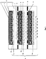
Interkonnektor (1) für eine Hochtemperatur-Brennstoffzelle, dadurch gekennzeichnet, – dass Seitenränder (9) des Interkonnektors (1) mittels eines elektrisch leitenden Mittels (8) mit einer Anode (2) elektrisch leitend verbunden sind, und – dass die Anode (2) und das elektrisch leitende Mittel (8) über wenigstens ein federndes Element (11) im Interkonnektor (1) gelagert sind.Interconnector (1) for a high-temperature fuel cell, characterized in - that the side edges (9) of the interconnector (1) are electrically conductively connected to an anode (2) by means of an electrically conductive means (8), and - that the anode (2 ) and the electrically conductive means (8) are mounted in the interconnector (1) via at least one resilient element (11).
Description
Die Erfindung bezieht sich auf einen Interkonnektor für Hochtemperaturbrennstoffzellen.The invention relates to an interconnector for high-temperature fuel cells.
Eine Brennstoffzelle weist eine Kathode, einen Elektrolyten sowie eine Anode auf. Der Kathode wird ein Oxidationsmittel, z. B. Luft und der Anode wird ein Brennstoff, z. B. Wasserstoff zugeführt.A fuel cell has a cathode, an electrolyte and an anode. The cathode becomes an oxidizing agent, e.g. B. air and the anode is a fuel, for. B. hydrogen supplied.
Verschiedene Brennstoffzellentypen sind bekannt, beispielsweise die SOFC-Brennstoffzelle aus der Druckschrift
Die SOFC-Brennstoffzelle wird auch Hochtemperaturbrennstoffzelle genannt, da ihre Betriebstemperatur bis zu 1000°C betragen kann. An der Kathode einer Hochtemperaturbrennstoffzelle bilden sich in Anwesenheit des Oxidationsmittels Sauerstoffionen. Die Sauerstoffionen diffundieren durch den Elektrolyten und rekombinieren auf der Anodenseite mit dem vom Brennstoff stammenden Wasserstoff zu Wasser. Mit der Rekombination werden Elektronen freigesetzt und so elektrische Energie erzeugt.The SOFC fuel cell is also called a high-temperature fuel cell because its operating temperature can be up to 1000 ° C. At the cathode of a high temperature fuel cell oxygen ions are formed in the presence of the oxidant. The oxygen ions diffuse through the electrolyte and recombine on the anode side with the fuel-derived hydrogen to water. Recombination releases electrons, generating electrical energy.
Mehrere Brennstoffzellen werden in der Regel zur Erzielung großer elektrischer Leistungen durch verbindende Elemente, auch Interkonnektoren genannt, elektrisch und mechanisch miteinander verbunden. Mittels Interkonnektoren entstehen übereinander gestapelte, elektrisch in Serie geschaltete Brennstoffzellen. Diese Anordnung wird Brennstoffzellenstapel genannt. Die Brennstoffzellenstapel bestehen aus den Interkonnektoren und den Elektroden-Elektrolyt-Einheiten.As a rule, a plurality of fuel cells are connected to one another electrically and mechanically by interconnecting elements, also called interconnectors. By means of interconnectors arise stacked, electrically connected in series fuel cells. This arrangement is called a fuel cell stack. The fuel cell stacks consist of the interconnectors and the electrode-electrolyte units.
Interkonnektoren besitzen neben den elektrischen und mechanischen Eigenschaften regelmäßig auch Gasverteilerstrukturen. Dies wird durch Stege und Nuten realisiert (
Nachteilig können bei Brennstoffzellen und Brennstoffzellenstapeln folgende Probleme auftreten:
- – Metallische Interkonnektoren mit hohem Aluminiumgehalt bilden Al2O3-Deckschichten aus, die nachteilig wie ein elektrischer Isolator wirken.
- – Bei zyklischer Temperaturbelastung treten allgemein Wärmespannungen, verbunden mit Relativbewegungen der Einzelkomponenten zueinander, auf; diese resultieren aus dem unterschiedlichen Ausdehnungsverhalten bzw. den unterschiedlichen Ausdehnungskoeffizienten der verwendeten Materialien im Betrieb.
- Metallic interconnectors with a high aluminum content form Al 2 O 3 cover layers which disadvantageously act like an electrical insulator.
- - At cyclic temperature stress generally thermal stresses associated with relative movements of the individual components to each other, on; These result from the different expansion behavior or the different coefficients of expansion of the materials used in operation.
Diesbezüglich besteht im Stand der Technik noch keine ausreichende Kompatibilität zwischen den vergleichsweise hohen Ausdehnungskoeffizienten z. B. des metallischen Interkonnektors und den derzeit bekannten Elektrodenmaterialien, deren Ausdehnungskoeffizienten vergleichsweise gering sind. Wärmespannungen können einerseits zwischen Elektroden und Interkonnektoren auftreten. Diese können Zerstörungen innerhalb der Brennstoffzelle zur Folge haben. Dies betrifft andererseits aber auch die in Brennstoffzellen häufig eingesetzten Glaslote, die die Dichtigkeit der Brennstoffzellen gewährleisten sollen. Beim Fügeprozess wird der Brennstoffzellenstapel auf etwa 700 bis 900°C erwärmt und mit 1 bis 5 kN zusammengepresst. Dabei wird das Glaslot weich, so dass unter dem Fügedruck zum einen die verschiedenen Fugen zwischen Zellen, Interkonnektoren und Gehäuse abgedichtet werden und zum anderen wird gleichzeitig ein Anpressdruck zur elektrischen Kontaktierung von Zellen und Interkonnektoren erreicht. Nachteilig bei dieser Anordnung ist es, dass das Glaslot bereits nach einigen Stunden Betriebszeit kristallisiert und dadurch spröde und hart wird. Das elastische Verhalten geht verloren. Dies hat zur Folge, dass sich die von außen auf den Stapel aufgeprägte Anpresskraft unregelmäßig und unkontrolliert auf die äußere Dichtungskraft und die innere Kontaktierungskraft aufteilt. Beim längeren Betrieb des Brennstoffzellenstapels bei 700 bis 900°C treten drüber hinaus Kriechvorgänge in den einzelnen Werkstoffschichten des Stapels und vor allem Schrumpfungen in der zunächst ungesinterten Kathodenkontaktschicht auf. Somit kann eine zuverlässige Kontaktkraft zwischen Zellen und Interkonnektoren nicht mehr aufrecht gehalten werden und die elektrische Kontaktierung geht verloren. Die Brennstoffzelle ist nicht mehr funktionstüchtig.In this regard, in the prior art is still no sufficient compatibility between the relatively high expansion coefficients z. As the metallic interconnector and the currently known electrode materials whose expansion coefficients are relatively low. Thermal stresses can occur on the one hand between electrodes and interconnectors. These can result in destruction within the fuel cell. On the other hand, this also applies to the glass solders frequently used in fuel cells, which are intended to ensure the tightness of the fuel cells. During the joining process, the fuel cell stack is heated to about 700 to 900 ° C and compressed with 1 to 5 kN. In this case, the glass solder is soft, so that under the joining pressure on the one hand, the various joints between cells, interconnectors and housing are sealed and on the other hand, a contact pressure for electrical contacting of cells and interconnectors is achieved. The disadvantage of this arrangement is that the glass solder crystallizes after a few hours of operation and thus becomes brittle and hard. The elastic behavior is lost. This has the consequence that the impressed from outside on the stack contact pressure irregular and uncontrolled on the outer sealing force and the internal contacting force. During prolonged operation of the fuel cell stack at 700 to 900 ° C, moreover, creep processes occur in the individual material layers of the stack and, above all, shrinkage in the initially unsintered cathode contact layer. Thus, a reliable contact force between cells and interconnectors can no longer be maintained and the electrical contact is lost. The fuel cell is no longer functional.
Aufgabe der Erfindung ist es daher, einen Interkonnektor für eine Hochtemperaturbrennstoffzelle bereit zu stellen, der eine langzeitstabile mechanischelektrische Kontaktierung zwischen Anode und Interkonnektor gewährleistet.The object of the invention is therefore to provide an interconnector for a high-temperature fuel cell, which ensures a long-term stable mechanical electrical contact between the anode and interconnector.
Diese Aufgabe wird durch einen Interkonnektor für eine Hochtemperaturbrennstoffzelle nach Anspruch 1 gelöst. Sie ist gekennzeichnet durch einen Interkonnektor, dessen Seitenränder mittels eines elektrisch leitenden Mittels elektrisch leitend mit der Anode kontaktiert sind sowie dessen Anode über federnde Elemente im Interkonnektor gelagert ist. Durch diese Ausgestaltung des Interkonnektors ist es möglich, eine Entkopplung von Dichtungs- und Kontaktierungskraft zu erreichen. Während nach dem bisher bekannten Stand der Technik z. B. ein elektrisch leitendes Mittel sowohl für die stabile elektrische Kontaktierung als auch für eine stabile mechanische Kontaktierung und Abdichtung verantwortlich war, wird diese Aufgabe durch die vorliegende Erfindung auf zwei Vorrichtungselemente aufgeteilt: federnde Elemente, welche für eine stabile mechanische Kontaktierung und Abdichtung der Brennstoffzelle sorgen und ein elektrisch leitendes Mittel, welches über die Seitenränder des Interkonnektors mit der Anode kontaktiert ist und damit für die stabile elektrische Kontaktierung sorgt. Die federnden Elemente müssen keinen Strom mehr übertragen. Im Unterschied zum Stand der Technik fließt der Strom nicht mehr direkt vertikal zwischen Anode und Interkonnektor. Statt dessen wird der Strom über die Seitenränder des Interkonnektors umgeleitet.This object is achieved by an interconnector for a high-temperature fuel cell according to
In einer vorteilhaften Ausgestaltung der Vorrichtung bestehen die federnden Elemente beispielsweise aus Einzelelementen, mit einem kreisförmigen, C-förmigen oder S-förmigen Querschnitt oder aus einer federnden Schicht oder federnden Streifen. Diese federnde Schicht oder die Streifen können beispielsweise aus Glimmer bestehen. Glimmer bezeichnet eine Gruppe im monoklinen Kristallsystem kristallisierender Silikat -Minerale mit der komplexen chemischen Zusammensetzung (K, Na, Ca) (Al, Mg, Fe, Li) 2-3 (OH) 2 (Si, Al) 4-5010. Die in Klammern stehenden Atome können sich in beliebiger Mischung vertreten, stehen aber immer im selben Verhältnis zu den anderen Atomgruppen (freie Enzyklopädie Wikipedia). Die kreisförmigen, C-förmig, oder S-förmig ausgestalteten Einzelelemente können beispielsweise aus hochtemperaturfesten Stahlröhren, Profilstäben oder Stahlblechen bestehen. Die federnden Einzelelemente können eine Höhe von 1–2 mm aufweisen, um eine ausreichende Federung zu gewährleisten und Relativbewegungen auszugleichen. über die frei wählbare Steifigkeit der federnden Einzelelemente kann die Kontaktierungskraft gezielt eingestellt werden. Glimmer ist gegenüber den kreisförmigen, C-förmigen oder S-förmigen Elementen weniger federnd, weist aber eine höhere Temperaturstabilität auf und ist kostengünstiger. Innerhalb der Gruppe der kreisförmig, C-förmig oder S-förmig ausgestalteten Einzelelemente, weisen die kreisförmigen Elemente eine stärkere Steifigkeit gegenüber den C- oder S-förmig ausgestalteten Elementen auf.In an advantageous embodiment of the device, the resilient elements consist for example of individual elements, with a circular, C-shaped or S-shaped cross-section or of a resilient layer or resilient strips. This resilient layer or the strips may for example consist of mica. Mica denotes a group in the monoclinic crystal system of crystallizing silicate minerals with the complex chemical composition (K, Na, Ca) (Al, Mg, Fe, Li) 2-3 (OH) 2 (Si, Al) 4-5010. The bracketed atoms can be represented in any mixture, but are always in the same ratio to the other atomic groups (Wikipedia). The circular, C-shaped, or S-shaped individual elements may for example consist of high temperature resistant steel tubes, profiled bars or steel sheets. The resilient individual elements may have a height of 1-2 mm, to ensure sufficient suspension and compensate for relative movements. On the freely selectable stiffness of the resilient individual elements, the contacting force can be adjusted specifically. Mica is less resilient than the circular, C-shaped or S-shaped elements, but has a higher temperature stability and is less expensive. Within the group of circular, C-shaped or S-shaped individual elements, the circular elements have a greater rigidity compared to the C- or S-shaped configured elements.
Die Vorrichtung weist in vorteilhafter Weise ein elektrisch leitendes Mittel auf, welches aus Nickel, Gold, Platin oder Silber besteht. So kann beispielsweise ein Nickelnetz eingesetzt werden, welches einen Drahtdurchmesser von 0,6 mm und einen Drahtabstand von 2,6 mm hat. Es ist jedoch auch möglich, ein dünnes Blech oder eine Folie aus dem geeigneten Material einzusetzen. Die elektrisch leitenden Mittel können an den Seitenrändern des Interkonnektors elektrisch leitend mit diesem z. B. durch Hochtemperaturlöten/-schweißen verbunden werden oder sie können in vorgefertigte Rillen des Interkonnektorrands eingestemmt oder dort verlötet werden.The device advantageously comprises an electrically conductive agent consisting of nickel, gold, platinum or silver. For example, a nickel mesh can be used which has a wire diameter of 0.6 mm and a wire spacing of 2.6 mm. However, it is also possible to use a thin sheet or a foil of the appropriate material. The electrically conductive means may be electrically conductive at the side edges of the interconnector with this z. B. by high temperature soldering / welding or they can be caulked in prefabricated grooves of the interconnector edge or soldered there.
In einer weiteren vorteilhaften Ausführung der Vorrichtung ist die innere Glaslotdichtung über ein federndes Element mit dem angrenzenden Interkonnektor verbunden. Biegespannungen, die im Randbereich der Brennstoffzelle auftreten, können hierdurch verringert werden und so eine Bruchgefahr der Brennstoffzelle verhindern. Dieses federnde Element kann beispielsweise ein Aluchromstreifen sein, der kreisförmig, C-förmig oder S-förmig ausgestaltet ist.In a further advantageous embodiment of the device, the inner glass solder seal is connected via a resilient element with the adjacent interconnector. Bending stresses that occur in the edge region of the fuel cell can thereby be reduced and thus prevent a risk of breakage of the fuel cell. This resilient element may for example be an Aluchromstreifen, which is configured circular, C-shaped or S-shaped.
Alternativ zu den bisher verwendeten Glaslotdichtungen für die Interkonnektoren untereinander, können auch metallische Dichtungen eingesetzt werden, die nicht elektrisch isoliert sind und Relativbewegungen an den Rändern der Interkonnektoren, die miteinander verbunden sind, ausgleichen können. Dies ist nun möglich, da die hohen Kräfte für die metallische Dichtung durch die entsprechende Dimensionierung der federnden Elemente nicht mehr unkontrolliert auf die Brennstoffzelle geleitet werden, sondern die Kontaktierungskraft entsprechend der frei wählbaren Steifigkeit der federnden Elemente bestimmbar ist. Die elektrische Isolierung der metallischen Dichtung kann durch eine Keramikschicht auf dem Interkonnektorrand oder eine Beschichtung der metallischen Dichtung mit einer Keramikschicht (z. B. Zirkonoxidschicht) erfolgen.As an alternative to the previously used glass solder seals for the interconnectors with each other, and metallic seals can be used, which are not electrically insulated and can compensate for relative movements at the edges of the interconnectors, which are interconnected. This is now possible because the high forces for the metallic seal are no longer passed uncontrollably through the appropriate dimensioning of the resilient elements on the fuel cell, but the contacting force is determined according to the arbitrary stiffness of the resilient elements. The electrical insulation of the metallic seal can be effected by a ceramic layer on the interconnector edge or a coating of the metallic seal with a ceramic layer (eg zirconium oxide layer).
Die Aufgabe wird weiterhin gelöst durch ein Verfahren zur Herstellung des erfindungsgemäßen Interkonnektors.The object is further achieved by a method for producing the interconnector according to the invention.
Im Folgenden wird die Erfindung unter anderem auch anhand der Beschreibung eines Ausführungsbeispiels und unter Bezugnahme auf die beigefügte Figur erläutert.In the following, the invention will be explained inter alia on the basis of the description of an embodiment and with reference to the accompanying figure.
Es zeigt:It shows:
Auf die innere Glaslotdichtung
Zur Abdichtung der Interkonnektoren (
Claims (11)
Priority Applications (5)
| Application Number | Priority Date | Filing Date | Title |
|---|---|---|---|
| DE102005014077A DE102005014077B4 (en) | 2005-03-23 | 2005-03-23 | Interconnector for high-temperature fuel cells and method for its production and method for operating a fuel cell |
| US11/887,154 US8153327B2 (en) | 2005-03-23 | 2006-02-16 | Interconnector for high temperature fuel cells |
| EP06722490A EP1866989A1 (en) | 2005-03-23 | 2006-02-16 | Interconnector for high temperature fuel cells |
| PCT/DE2006/000277 WO2006099830A1 (en) | 2005-03-23 | 2006-02-16 | Interconnector for high temperature fuel cells |
| JP2008502233A JP2008535149A (en) | 2005-03-23 | 2006-02-16 | Interconnects for high temperature fuel cells |
Applications Claiming Priority (1)
| Application Number | Priority Date | Filing Date | Title |
|---|---|---|---|
| DE102005014077A DE102005014077B4 (en) | 2005-03-23 | 2005-03-23 | Interconnector for high-temperature fuel cells and method for its production and method for operating a fuel cell |
Publications (2)
| Publication Number | Publication Date |
|---|---|
| DE102005014077A1 DE102005014077A1 (en) | 2006-10-05 |
| DE102005014077B4 true DE102005014077B4 (en) | 2012-05-24 |
Family
ID=36201526
Family Applications (1)
| Application Number | Title | Priority Date | Filing Date |
|---|---|---|---|
| DE102005014077A Expired - Fee Related DE102005014077B4 (en) | 2005-03-23 | 2005-03-23 | Interconnector for high-temperature fuel cells and method for its production and method for operating a fuel cell |
Country Status (5)
| Country | Link |
|---|---|
| US (1) | US8153327B2 (en) |
| EP (1) | EP1866989A1 (en) |
| JP (1) | JP2008535149A (en) |
| DE (1) | DE102005014077B4 (en) |
| WO (1) | WO2006099830A1 (en) |
Families Citing this family (5)
| Publication number | Priority date | Publication date | Assignee | Title |
|---|---|---|---|---|
| DE102006056251B4 (en) * | 2006-11-27 | 2009-04-09 | Bayerische Motoren Werke Aktiengesellschaft | High temperature fuel cell with ferritic component and method of operating the same |
| JP5591743B2 (en) * | 2011-03-11 | 2014-09-17 | 日本特殊陶業株式会社 | Solid oxide fuel cell |
| JP5607561B2 (en) * | 2011-03-11 | 2014-10-15 | 日本特殊陶業株式会社 | Solid oxide fuel cell |
| DE102015205944B4 (en) * | 2015-03-30 | 2021-02-18 | Fraunhofer-Gesellschaft zur Förderung der angewandten Forschung e.V. | Arrangement of electrochemical cells with sealing layers and their use |
| JP7236675B2 (en) * | 2018-08-01 | 2023-03-10 | パナソニックIpマネジメント株式会社 | Solid oxide fuel cell and electrochemical cell |
Citations (3)
| Publication number | Priority date | Publication date | Assignee | Title |
|---|---|---|---|---|
| DE4016157A1 (en) * | 1989-06-08 | 1990-12-13 | Asea Brown Boveri | High temp. fuel cell stack - with cells series-connected by separator plates and elastic current collectors |
| WO2001004981A1 (en) * | 1999-07-09 | 2001-01-18 | Siemens Aktiengesellschaft | Electrical bonding protected against oxidation on the gas combustion side of a high temperature fuel cell |
| DE10033898A1 (en) * | 2000-07-12 | 2002-01-31 | Forschungszentrum Juelich Gmbh | High-temperature fuel cell |
Family Cites Families (14)
| Publication number | Priority date | Publication date | Assignee | Title |
|---|---|---|---|---|
| US121334A (en) * | 1871-11-28 | Improvement in upright pianos | ||
| DE1033898B (en) | 1952-03-20 | 1958-07-10 | Atlas Powder Co | Process for the production of thermoplastic, powdery, hardenable polyester resins |
| EP0446680A1 (en) | 1990-03-15 | 1991-09-18 | Asea Brown Boveri Ag | Current collector for conducting current between neighbouring piled high temperature fuel cells |
| DE4410711C1 (en) * | 1994-03-28 | 1995-09-07 | Forschungszentrum Juelich Gmbh | Metallic bipolar plate for HT fuel cells and method of manufacturing the same |
| DE4430958C1 (en) | 1994-08-31 | 1995-10-19 | Forschungszentrum Juelich Gmbh | Solid electrolyte high temperature fuel cell and fuel cell assembly |
| DE19531852C1 (en) | 1995-08-30 | 1996-12-19 | Forschungszentrum Juelich Gmbh | Fuel cell with drainage system for water or steam |
| WO2001001981A1 (en) | 1999-07-01 | 2001-01-11 | Taisho Pharmaceutical Co., Ltd. | Vegf receptor antagonists |
| DE10033897A1 (en) * | 2000-07-12 | 2002-01-31 | Forschungszentrum Juelich Gmbh | Aluminum-containing interconnector for fuel cells |
| US7222406B2 (en) * | 2002-04-26 | 2007-05-29 | Battelle Memorial Institute | Methods for making a multi-layer seal for electrochemical devices |
| US8048587B2 (en) * | 2002-11-27 | 2011-11-01 | Delphi Technologies, Inc. | Compliant current collector for fuel cell anode and cathode |
| JP4639583B2 (en) * | 2003-03-06 | 2011-02-23 | トヨタ自動車株式会社 | Fuel cell |
| DE10317388B4 (en) | 2003-04-15 | 2009-06-10 | Bayerische Motoren Werke Aktiengesellschaft | Fuel cell and / or electrolyzer and process for their preparation |
| DE10317361A1 (en) * | 2003-04-15 | 2004-11-04 | Bayerische Motoren Werke Ag | Fuel cell and / or electrolyser and process for their production |
| US20050136312A1 (en) * | 2003-12-22 | 2005-06-23 | General Electric Company | Compliant fuel cell system |
-
2005
- 2005-03-23 DE DE102005014077A patent/DE102005014077B4/en not_active Expired - Fee Related
-
2006
- 2006-02-16 EP EP06722490A patent/EP1866989A1/en not_active Withdrawn
- 2006-02-16 WO PCT/DE2006/000277 patent/WO2006099830A1/en not_active Application Discontinuation
- 2006-02-16 JP JP2008502233A patent/JP2008535149A/en not_active Withdrawn
- 2006-02-16 US US11/887,154 patent/US8153327B2/en not_active Expired - Fee Related
Patent Citations (3)
| Publication number | Priority date | Publication date | Assignee | Title |
|---|---|---|---|---|
| DE4016157A1 (en) * | 1989-06-08 | 1990-12-13 | Asea Brown Boveri | High temp. fuel cell stack - with cells series-connected by separator plates and elastic current collectors |
| WO2001004981A1 (en) * | 1999-07-09 | 2001-01-18 | Siemens Aktiengesellschaft | Electrical bonding protected against oxidation on the gas combustion side of a high temperature fuel cell |
| DE10033898A1 (en) * | 2000-07-12 | 2002-01-31 | Forschungszentrum Juelich Gmbh | High-temperature fuel cell |
Also Published As
| Publication number | Publication date |
|---|---|
| DE102005014077A1 (en) | 2006-10-05 |
| US8153327B2 (en) | 2012-04-10 |
| EP1866989A1 (en) | 2007-12-19 |
| WO2006099830A1 (en) | 2006-09-28 |
| US20090061300A1 (en) | 2009-03-05 |
| JP2008535149A (en) | 2008-08-28 |
Similar Documents
| Publication | Publication Date | Title |
|---|---|---|
| WO2003032420A2 (en) | High-temperature resistant seal | |
| DE4237602A1 (en) | High temperature fuel cell stack and process for its manufacture | |
| EP1844513B1 (en) | Interconnector for high-temperature fuel cells | |
| EP1314217B1 (en) | High temperature fuel cell | |
| DE102005014077B4 (en) | Interconnector for high-temperature fuel cells and method for its production and method for operating a fuel cell | |
| DE19805142A1 (en) | Long life high temperature fuel cell with mechanically and chemically stable joint | |
| DE102009003074A1 (en) | Electrochemical cell for obtaining electrical energy | |
| DE102005005117B4 (en) | High-temperature fuel cell, fuel cell stack, method for producing an interconnector | |
| DE102011000180A1 (en) | Anode-supported flat tube SOFC and its manufacturing process | |
| EP0795204B1 (en) | Fuel cell with bipolar flanges coated with ceramic material and its production | |
| DE202013012667U1 (en) | Cell, cell stacking unit, electrochemical module and electrochemical device | |
| EP1981108B1 (en) | Interconnector assembly and method for manufacturing a connector assembly for a fuel cell stack | |
| DE102022121234A1 (en) | Electrochemical reaction cell stack | |
| EP1358692A1 (en) | Fuel cells | |
| WO2005027247A1 (en) | Interconnector for high-temperature fuel cell unit | |
| DE10350478B4 (en) | fuel cell unit | |
| DE10301404B4 (en) | Fuel cell, fuel cell stack and its production process | |
| DE112010002963B4 (en) | Process for the preparation of an electrochemical energy converter and the electrochemical energy converter | |
| DE10342493B4 (en) | Fuel cell module and fuel cell battery | |
| EP2850687B1 (en) | Electrical energy store | |
| DE102011051440A1 (en) | Inter-connector manufacturing method for high temperature fuel cell, involves attaching pin-shaped contact member on inter-connector base element directly or indirectly by welding process, where contact member is connected with spring | |
| DE19808859C2 (en) | Fuel cell stack with conductor | |
| DE102021131474A1 (en) | Electrochemical reaction single cell and electrochemical reaction cell stack | |
| DE112019007178T5 (en) | Electrochemical reaction cell stack | |
| EP1301957B1 (en) | Aluminous interconnector for fuel cells |
Legal Events
| Date | Code | Title | Description |
|---|---|---|---|
| OP8 | Request for examination as to paragraph 44 patent law | ||
| R018 | Grant decision by examination section/examining division | ||
| R020 | Patent grant now final |
Effective date: 20120825 |
|
| R119 | Application deemed withdrawn, or ip right lapsed, due to non-payment of renewal fee |
Effective date: 20131001 |