EP1600989B1 - Kontaktsystem - Google Patents
Kontaktsystem Download PDFInfo
- Publication number
- EP1600989B1 EP1600989B1 EP04012444A EP04012444A EP1600989B1 EP 1600989 B1 EP1600989 B1 EP 1600989B1 EP 04012444 A EP04012444 A EP 04012444A EP 04012444 A EP04012444 A EP 04012444A EP 1600989 B1 EP1600989 B1 EP 1600989B1
- Authority
- EP
- European Patent Office
- Prior art keywords
- contact
- spring element
- spring
- holder
- movable
- Prior art date
- Legal status (The legal status is an assumption and is not a legal conclusion. Google has not performed a legal analysis and makes no representation as to the accuracy of the status listed.)
- Expired - Lifetime
Links
- 239000012811 non-conductive material Substances 0.000 claims abstract description 5
- 229920001971 elastomer Polymers 0.000 claims abstract description 4
- 239000000806 elastomer Substances 0.000 claims abstract description 4
- 229920001169 thermoplastic Polymers 0.000 claims abstract description 4
- 239000004416 thermosoftening plastic Substances 0.000 claims abstract description 4
- 239000000463 material Substances 0.000 claims description 8
- 238000007142 ring opening reaction Methods 0.000 claims description 2
- 239000002184 metal Substances 0.000 description 5
- 239000004033 plastic Substances 0.000 description 4
- 229920003023 plastic Polymers 0.000 description 4
- 238000009434 installation Methods 0.000 description 2
- 229920006393 polyether sulfone Polymers 0.000 description 2
- 229920002873 Polyethylenimine Polymers 0.000 description 1
- 238000001816 cooling Methods 0.000 description 1
- 238000013016 damping Methods 0.000 description 1
- 238000010438 heat treatment Methods 0.000 description 1
- 230000010354 integration Effects 0.000 description 1
- 238000004519 manufacturing process Methods 0.000 description 1
- 229920003208 poly(ethylene sulfide) Polymers 0.000 description 1
- 229920001601 polyetherimide Polymers 0.000 description 1
- 229920006324 polyoxymethylene Polymers 0.000 description 1
- 229920000069 polyphenylene sulfide Polymers 0.000 description 1
- 239000011435 rock Substances 0.000 description 1
- 230000011664 signaling Effects 0.000 description 1
- 239000007787 solid Substances 0.000 description 1
Images


Classifications
-
- H—ELECTRICITY
- H01—ELECTRIC ELEMENTS
- H01H—ELECTRIC SWITCHES; RELAYS; SELECTORS; EMERGENCY PROTECTIVE DEVICES
- H01H1/00—Contacts
- H01H1/12—Contacts characterised by the manner in which co-operating contacts engage
- H01H1/14—Contacts characterised by the manner in which co-operating contacts engage by abutting
- H01H1/24—Contacts characterised by the manner in which co-operating contacts engage by abutting with resilient mounting
- H01H1/26—Contacts characterised by the manner in which co-operating contacts engage by abutting with resilient mounting with spring blade support
-
- H—ELECTRICITY
- H01—ELECTRIC ELEMENTS
- H01H—ELECTRIC SWITCHES; RELAYS; SELECTORS; EMERGENCY PROTECTIVE DEVICES
- H01H1/00—Contacts
- H01H1/12—Contacts characterised by the manner in which co-operating contacts engage
- H01H1/14—Contacts characterised by the manner in which co-operating contacts engage by abutting
- H01H1/20—Bridging contacts
Definitions
- the invention relates to a contact system, in particular for an electromechanical switching device, such as contactor, position switch, command and signaling device or contactor safety combination.
- Such a contact system has both a fixed contact and a movable contact.
- the fixed contact serves for contacting a connecting cable or the like.
- the movable contact is used to open and close the contact system.
- the movable contact must be mounted so that the contact pieces of the movable and the fixed contact meet in a defined manner.
- the application of a defined contacting force is required.
- the movable contact should be largely decoupled from its drive or actuating element, for example a magnetic drive, slide, contact piece carrier, jump system or the like, to avoid negative kinetic influences.
- the object of the invention is to provide a contact system that requires a comparatively small space.
- the contact system has a fixed contact, in particular for contacting a connecting line, as well as an actuatable by a drive or actuator movable contact for opening and closing the electrical connection with the fixed contact.
- a contact holder for receiving the movable contact is provided.
- Connected to the contact holder is a spring element made of an electrically non-conductive material. This spring element serves to support the movable contact.
- the spring element is designed as a bridge spring, which connects the contact holder with a further contact holder, which also receives a movable contact for establishing an electrical connection to another fixed contact.
- a core idea of the invention is to substitute the spring material previously used for the spring element. Instead of a metallic spring now an electrically non-conductive spring elements is used. Clearances and creepage distances are not shortened, whereby a significant reduction in the required installation space is possible.
- a mounting element is provided which allows automated handling of the spring element. It is a mounting hole, which may have an inner contour.
- the contact holder also consists of an electrically non-conductive material, negative influences on the bearing of the spring element and contact holder or the position of the movable contact in heating or cooling can be further reduced in this case due largely the same temperature expansion coefficient.
- the material for the spring element according to a further advantageous embodiment of the invention is a thermoplastic (such as PES, PESU, PEI, PPS, POM, PA) or an elastomer.
- a thermoplastic such as PES, PESU, PEI, PPS, POM, PA
- elastomer such as PES, PESU, PEI, PPS, POM, PA
- plastics such as thermoplastics or elastomers also allows integration of functional surfaces on the contact holder.
- the assembly can be designed optimized assembly, for example, have guide and bearing surfaces. This reduces development, material and assembly costs.
- the functional surfaces are preferably designed for producing a snap, latching or press connection.
- the spring element in a further embodiment of the invention has a good tangible, for example, angular profile.
- a known contact system 1 shows FIG. 1 ,
- the movable contact 2 with its two end-mounted switching pieces 3 is attached to a contact holder 4.
- This contact holder has a receiving area 5 for the movable contact 2.
- the contact holder 4 is supported by a metal spring 6, which at the same time establishes the connection to the opposite, similarly constructed contact system 2 as a bridge spring.
- a drive or actuating element not shown
- the movable contact 2 is moved towards a fixed contact 7 in the contacting direction 8, wherein the switching pieces 3 of the movable contact 3 and the fixed contact 7 in a defined manner to each other to meet.
- FIGS. 2 to 6 show contact holder 10 with spring elements 11 of electrically non-conductive material.
- spring elements 11 of electrically non-conductive material.
- the two in FIG. 2 illustrated contact holder 10 for movable contacts are connected to each other via an electrically non-conductive spring element 11 in the manner of a coil spring.
- the spring element 11 can also have other shapes, as illustrated in the following figures.
- the spring action is predetermined primarily by the contour design of the spring element 11 and beyond by the appropriate selection of an elastic or elastoplastic material for the spring element 11th
- spring element 11 has at its contact ends 12 flat end surfaces 13.
- the spring element 11 is inserted with its end faces 13 in this provided receiving openings 14 on the contact holders 10 and pushed onto corresponding contact projections.
- Each contact holder 10 has a receiving area 15 for receiving a movable contact (not shown).
- Each receiving area 15 comprises two receiving element pairs.
- Each receiving element pair has two spaced apart and extending in the connecting direction 16 receiving elements 17.
- a snap-fit or latching hook 18 is provided on each receiving element 17.
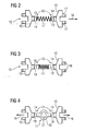
- FIG. 3 shows a further embodiment of a spring element 11 according to the helical spring type.
- This spring element 11 has end functional surfaces 19. These functional surfaces 19 are used to store or fix the spring element 11 to the contact holders 10. They are preferably designed to form a snap or latching connection between spring element 11 and contact holder 10. In a production of the spring element 11 made of a plastic material, the functional surfaces 19 may advantageously be integrated or molded.
- the illustrated embodiment has a spring element 11 in the manner of an annular disc with a compressed oval cross-section, wherein the functional surfaces 19 are integrally formed on both sides of the spring ring 20.
- the ring opening 21 also serves as a mounting hole for the assembly of the spring element 11.
- FIGS. 5 and 6 show a further embodiment of a contact holder 10, wherein the spring element 11 is designed as a hollow ball. Illustrated FIG. 5 a view with partially cut spring element 11, while FIG. 6 depicts a top view. Instead of a hollow ball and a solid ball can be used. In FIG. 7 a contact holder 10 is shown with a meandering spring element 11.
- the present invention can be used for any type of contact system, in particular for contact systems with a bridge spring or the like for defined application of a contact force. This applies to both contact systems with jump or creep system, in particular position switches, as well as solenoid-operated contact systems, in particular contactors.
Landscapes
- Push-Button Switches (AREA)
- Coupling Device And Connection With Printed Circuit (AREA)
- Manufacturing Of Electrical Connectors (AREA)
- Thermally Actuated Switches (AREA)
- Contacts (AREA)
Description
- Die Erfindung betrifft ein Kontaktsystem, insbesondere für ein elektromechanisches Schaltgerät, beispielsweise Schütz, Positionsschalter, Befehls- und Meldegerät oder Schützsicherheitskombination.
- Ein derartiges Kontaktsystem weist sowohl einen festen Kontakt als auch einen beweglichen Kontakt auf. Der feste Kontakt dient dabei zur Kontaktierung einer Anschlussleitung oder dergleichen. Der bewegliche Kontakt dient zum Öffnen und Schließen des Kontaktsystems. Hierfür muss der bewegliche Kontakt derart gelagert sein, dass die Schaltstücke des beweglichen und des festen Kontaktes in definierter Art und Weise aufeinandertreffen. Für eine sichere Kontaktierung ist zudem das Aufbringen einer definierten Kontaktierungskraft erforderlich. Außerdem soll der bewegliche Kontakt von seinem Antriebs- oder Betätigungselement, beispielsweise einem Magnetantrieb, Schieber, Schaltstückträger, Sprungsystem oder ähnlichem, zur Vermeidung negativer kinetischer Einflüsse weitgehend entkoppelt sein.
- Hierzu ist es aus dem Stand der Technik bekannt, den beweglichen Kontakt mittels einer Metallfeder zu lagern, welche direkt oder indirekt, beispielsweise über einen beweglichen Kontakthalter oder ein Sprungsystem, den beweglichen Kontakt beaufschlagt. Diese Metallfeder führt nicht nur zu einer Verkürzung der Luft- und Kriechstrecken, sondern verursacht auch als zusätzliches Bauteil höhere Material- und Montagekosten und erhöht das Fehlerrisiko der gesamten Baugruppe.
- Aus
US 4,405,848 ist eine elektrische Kontaktanordnung gemäß Oberbegriff des Anspruchs 1 bekannt, bei der Kunststoff-Federelement als Brückenfeder eingesetzt wird, um eine elektrische Verbindung zwischen beweglichen und festen Kontakten herzustellen.DE 1 276 163 beschreibt einen Wipp- oder Kipphebel-Schalter mit einem Druckorgan aus Kunststoff, welches eine schwenkbar gelagerte Kontaktwippe derart beaufschlagt, daß ein an der Kontaktwippe angebrachter Kontakt einen Festkontakt kontaktiert. InUS 3,229,062 ist ein elektrischer Schalter mit einem elastischen Element beschrieben, welches zunächst durch ein Betätigungsglied komprimiert wird und bei einer weiteren Betätigung des Betätigungsgliedes das Schließen eines elektrischen Kontaktes hervorruft. - Aufgabe der Erfindung ist es, ein Kontaktsystem bereitzustellen, das einen vergleichsweise geringen Bauraum benötigt.
- Diese Aufgabe wird durch ein Kontaktsystem nach Anspruch 1 gelöst. Danach weist das Kontaktsystem einen festen Kontakt, insbesondere zur Kontaktierung einer Anschlussleitung, sowie einen von einem Antriebs- oder Betätigungselement betätigbaren bewegliche Kontakt zum Öffnen und Schließen der elektrischen Verbindung mit dem festen Kontakt auf. Darüber hinaus ist ein Kontakthalter zur Aufnahme des beweglichen Kontaktes vorgesehen. Mit dem Kontakthalter verbunden ist ein Federelement aus einem elektrisch nicht leitenden Werkstoff. Dieses Federelement dient der Federung des beweglichen Kontaktes. Das Federelement ist als Brückenfeder ausgebildet, die den Kontakthalter mit einem weiteren Kontakthalter verbindet, der ebenfalls einen beweglichen Kontakt aufnimmt zur Herstellung einer elektrischen Verbindung zu einem weiteren festen Kontakt.
- Ein Kerngedanke der Erfindung ist es, den bisher für das Federelement verwendeten Federwerkstoff zu substituieren. Anstelle einer metallischen Feder wird nun ein elektrisch nicht leitendes Federelementeingesetzt. Luft- und Kriechstrecken werden nicht verkürzt, wodurch eine deutliche Reduzierung des erforderlichen Bauraumes möglich ist. Zweckmäßigerweise ist ein Montageelement vorgesehen, welches eine automatisierte Handhabung des Federelementes ermöglicht. Dabei handelt es sich um eine Montagebohrung, die eine Innenkontur aufweisen kann.
- Vorteilhafte Ausführungsformen der Erfindung sind in den Unteransprüchen angegeben.
- Besteht der Kontakthalter ebenfalls aus einem elektrisch nicht leitenden Material, können negative Einflüsse auf die Lagerstelle von Federelement und Kontakthalter oder die Position des beweglichen Kontaktes bei Erwärmung oder Kühlung können in diesem Fall aufgrund weitestgehend gleicher Temperaturausdehnungskoeffizienten weiter verringert werden.
- Bei dem Material für das Federelement handelt es sich gemäß einer weiteren vorteilhaften Ausführungsform der Erfindung um ein Thermoplast (wie beispielsweise PES, PESU, PEI, PPS, POM, PA) oder ein Elastomer. Das ungünstige Nachschwingen des beweglichen Kontaktes wird im Vergleich zur Verwendung einer Metallfeder reduziert, da derartige Werkstoffe eine größere Dämpfungskonstante als Metall aufweisen.
- Die Verwendung von Kunststoffen wie Thermoplasten oder Elastomeren erlaubt zugleich eine Integration von Funktionsflächen am Kontakthalter. Hierdurch kann die Baugruppe montageoptimiert gestaltet sein, beispielsweise Führungs- und Lagerflächen aufweisen. Dies reduziert Entwicklungs-, Material-und Montagekosten. Die Funktionsflächen sind dabei vorzugsweise zur Herstellung einer Schnapp-, Rast- oder Pressverbindung ausgebildet.
- Zur besseren Handhabung durch einen Greifer weist das Federelement in einer weiteren Ausführungsform der Erfindung ein gut greifbares, beispielsweise eckiges Profil auf.
- Die vorliegende Erfindung wird nachfolgend anhand von Ausführungsbeispielen näher beschrieben, die mit Hilfe der Zeichnungen erläutert werden. Hierbei zeigen:
- FIG 1
- eine schematische Darstellung eines Kontaktsystems nach dem Stand der Technik,
- FIG 2
- eine nicht erfindungsgemäße Ausführungsform eines Kontakthalters mit einem Federelement nach Art einer Schraubenfeder,
- FIG 3
- eine nicht erfindungsgemäße Ausführungsform eines Kontakthalters mit einem Federelement nach Art einer Schraubenfeder mit integrierten Funktionsflächen,
- FIF 4
- eine erfindungsgemäße Ausführungsform eines Kontakthalters mit einem Federelement nach Art eines federnden Ringes mit einer Montagebohrung,
- FIG 5 bis 6
- eine nicht erfindungsgemäße Ausführungsform eines Kontakthalters mit einem Federelement nach Art einer Kugel,
- FIG 7
- eine nicht erfindungsgemäße Ausführungsform eines Kontakthalters mit einem mäanderförmigen Federelement.
- Ein bekanntes Kontaktsystem 1 nach dem Stand der Technik zeigt
FIG 1 . Der bewegliche Kontakt 2 mit seinen beiden endseitig angebrachten Schaltstücken 3 ist dabei an einem Kontakthalter 4 angebracht. Dieser Kontakthalter weist einen Aufnahmebereich 5 für den beweglichen Kontakt 2 auf. Der Kontakthalter 4 wird durch eine Metallfeder 6 gelagert, welche als Brückenfeder zugleich die Verbindung zu dem gegenüberliegenden, gleichartig aufgebauten Kontaktsystem 2 herstellt. Bei einer Betätigung des Kontakts durch ein Antriebs- oder Betätigungselement (nicht abgebildet) wird der bewegliche Kontakt 2 auf einen festen Kontakt 7 in Kontaktierungsrichtung 8 zu bewegt, wobei die Schaltstücke 3 des beweglichen Kontaktes 3 und des festen Kontaktes 7 in definierter Art und Weise aufeinander treffen. - In den
FIG 2 bis 6 zeigen Kontakthalter 10 mit Federelementen 11 aus elektrisch nicht leitendem Material. Zur besseren Darstellung der Kontaktenden 12 der Federelemente 11 zeigen dieFIG 2 bis 6 Explosionsdarstellungen. - Die beiden in
FIG 2 abgebildeten Kontakthalter 10 für bewegliche Kontakte sind über ein elektrisch nicht leitendes Federelement 11 nach Art einer Schraubenfeder miteinander verbunden. Das Federelement 11 kann aber auch andere Formen aufweisen, wie in den nachfolgenden Figuren illustriert. Die Federwirkung wird dabei in erster Linie durch die Konturgestaltung des Federelementes 11 vorgegeben sowie darüber hinaus durch die geeignete Auswahl eines elastischen oder elastoplastischen Werkstoffes für das Federelement 11. - Das in
FIG 2 abgebildete Federelement 11 weist an seinen Kontaktenden 12 flache Endflächen 13 auf. Zur Montage wird das Federelement 11 mit seinen Endflächen 13 in hierfür vorgesehene Aufnahmeöffnungen 14 an den Kontakthaltern 10 eingeführt bzw. auf entsprechende Kontaktvorsprünge aufgeschoben. - Jeder Kontakthalter 10 weist einen Aufnahmebereich 15 zur Aufnahme eines beweglichen Kontaktes (nicht abgebildet) auf. Jeder Aufnahmebereich 15 umfasst dabei zwei Aufnahmeelemente-Paare. Jedes Aufnahmeelemente-Paar weist zwei voneinander beabstandete und sich in Verbindungsrichtung 16 erstreckende Aufnahmeelemente 17 auf. Zur Herstellung einer mechanischen Verbindung zwischen beweglichem Kontakt und Kontakthalter 10 ist an jedem Aufnahmeelement 17 ein Schnapp- oder Rasthaken 18 vorgesehen. Bei der Montage des beweglichen Kontaktes am Kontakthalter 10 wird der bewegliche Kontakt mit seinen entsprechend vorgesehenen Schnappausnehmungen auf die beiden Schnapphaken 18 des jeweiligen Aufnahmeelemente-Paares aufgeschoben.
-
FIG 3 zeigt eine weitere Ausführungsform eines Federelementes 11 nach Schraubenfederart. Dieses Federelement 11 weist endseitig Funktionsflächen 19 auf. Diese Funktionsflächen 19 dienen der Lagerung oder Fixierung des Federelements 11 an den Kontakthaltern 10. Sie sind vorzugsweise zur Ausbildung einer Schnapp- oder Rastverbindung zwischen Federelement 11 und Kontakthalter 10 ausgebildet. Bei einer Herstellung des Federelements 11 aus einem Kunststoffmaterial können die Funktionsflächen 19 zweckmäßigerweise integriert oder angespritzt werden. - Die in
FIG 4 abgebildete Ausführungsform weist ein Federelement 11 nach Art einer ringförmigen Scheibe mit einem gestauchten ovalen Querschnitt auf, wobei die Funktionsflächen 19 beidseitig am Federring 20 angeformt sind. Die Ringöffnung 21 dient zugleich als Montagebohrung für die Montage des Federelementes 11. So kann beispielsweise ein definiertes automatisches Aufnehmen und Handhaben des Federelementes 11 erfolgen, indem ein Montagestift in die Montagebohrung des Federelements 11 eingeführt und das Federelement 11 aufgenommen und bewegt wird. Eine manuelle Montage oder eine aufwändige Handhabung über Pressluft ist nicht mehr erforderlich. - Die
FIG 5 und 6 zeigen eine weitere Ausführungsform eines Kontakthalters 10, bei der das Federelement 11 als Hohlkugel ausgeführt ist. Dabei illustriertFIG 5 eine Ansicht mit teilweise aufgeschnittenem Federelement 11, währendFIG 6 eine Draufsicht abbildet. Anstelle einer Hohlkugel kann auch eine Vollkugel verwendet werden. InFIG 7 ist ein Kontakthalter 10 mit einem mäanderförmigen Federelement 11 abgebildet. - Die vorliegende Erfindung kann für beliebige Arten von Kontaktsystemen verwendet werden, insbesondere für Kontaktsysteme mit einer Brückenfeder oder dergleichen zum definierten Aufbringen einer Kontaktkraft. Dies betrifft sowohl Kontaktsysteme mit Sprung- oder Schleichsystem, insbesondere Positionsschalter, als auch magnetbetätigte Kontaktsysteme, insbesondere Schütze.
Claims (4)
- Kontaktsystem- mit einem ersten festen Kontakt,- mit einem ersten beweglichen Kontakt zur Herstellung einer elektrischen Verbindung mit dem ersten festen Kontakt,- mit einem ersten Kontakthalter (10) zur Aufnahme des ersten beweglichen Kontaktes,- mit einem zweiten festen Kontakt,- mit einem zweiten beweglichen Kontakt zur Herstellung einer elektrischen Verbindung mit dem zweiten festen Kontakt, dadurch gekennzeichnet, dass das Kontaktsystem- einen zweiten Kontakthalter (10) zur Aufnahme des zweiten beweglichen Kontaktes, und- ein Federelement (11) aus einem elektrisch nicht leitenden Werkstoff, welches als Brückenfeder eine Verbindung zwischen dem ersten Kontakthalter (10) und dem zweiten Kontakthalter herstellt und hierfür mit dem ersten Kontakthalter und mit dem zweiten Kontakthalter verbunden ist, aufweist, wobei das Federelement Montagebohrung (21) zur Aufnahme eines Montagestiftes oder dergleichen aufweist.
- Kontaktsystem nach Anspruch 1, gekennzeichnet durch ein Thermoplast oder ein Elastomer als Werkstoff für das Federelement (11).
- Kontaktsystem nach Anspruch 1 oder 2, dadurch gekennzeichnet, dass das Federelement ein Federring (20) ist und die Ringöffnung (21) als Montagebohrung dient.
- Kontaktsystem nach Anspruch 3, dadurch gekennzeichnet, dass der Federring (20) beidseitig zwei angeformte Funktionsflächen (19) aufweist zur Lagerung oder Fixierung an den Kontakthaltern (10).
Priority Applications (4)
| Application Number | Priority Date | Filing Date | Title |
|---|---|---|---|
| EP04012444A EP1600989B1 (de) | 2004-05-26 | 2004-05-26 | Kontaktsystem |
| DE502004006773T DE502004006773D1 (de) | 2004-05-26 | 2004-05-26 | Kontaktsystem |
| AT04012444T ATE392000T1 (de) | 2004-05-26 | 2004-05-26 | Kontaktsystem |
| US11/136,459 US7151233B2 (en) | 2004-05-26 | 2005-05-25 | Contact system |
Applications Claiming Priority (1)
| Application Number | Priority Date | Filing Date | Title |
|---|---|---|---|
| EP04012444A EP1600989B1 (de) | 2004-05-26 | 2004-05-26 | Kontaktsystem |
Publications (2)
| Publication Number | Publication Date |
|---|---|
| EP1600989A1 EP1600989A1 (de) | 2005-11-30 |
| EP1600989B1 true EP1600989B1 (de) | 2008-04-09 |
Family
ID=34925130
Family Applications (1)
| Application Number | Title | Priority Date | Filing Date |
|---|---|---|---|
| EP04012444A Expired - Lifetime EP1600989B1 (de) | 2004-05-26 | 2004-05-26 | Kontaktsystem |
Country Status (4)
| Country | Link |
|---|---|
| US (1) | US7151233B2 (de) |
| EP (1) | EP1600989B1 (de) |
| AT (1) | ATE392000T1 (de) |
| DE (1) | DE502004006773D1 (de) |
Families Citing this family (1)
| Publication number | Priority date | Publication date | Assignee | Title |
|---|---|---|---|---|
| US7994253B2 (en) * | 2008-04-15 | 2011-08-09 | Exxonmobil Chemical Patents Inc. | Translucent propylene-based elastomeric compositions |
Family Cites Families (15)
| Publication number | Priority date | Publication date | Assignee | Title |
|---|---|---|---|---|
| GB1012706A (en) * | 1963-04-02 | 1965-12-08 | Lucas Industries Ltd | Snap action electric switches |
| DE1276163B (de) * | 1967-04-29 | 1968-08-29 | Busch Jaeger Duerener Metall | Wipp- oder Kipphebelschalter |
| US3762684A (en) * | 1971-04-26 | 1973-10-02 | Anonda Plastics Inc | Rotatable pipe coupling |
| CA1156695A (en) * | 1979-10-10 | 1983-11-08 | Macmillan Bloedel Limited | Self protecting spray nozzle |
| DE3031725A1 (de) * | 1980-08-22 | 1982-04-01 | Siemens AG, 1000 Berlin und 8000 München | Kontaktanordnung |
| WO1996027727A1 (en) * | 1995-03-06 | 1996-09-12 | Norbert Marocco | Combined tilt and raise control for window coverings |
| DE19619249A1 (de) * | 1996-05-13 | 1997-11-20 | Voith Sulzer Papiermasch Gmbh | Auftragwerk zum direkten oder indirekten Auftragen eines flüssigen oder pastösen Mediums auf eine laufende Materialbahn |
| US6354715B1 (en) * | 1998-01-26 | 2002-03-12 | Bison Sportslights, Inc. | Flashlight |
| US6615006B2 (en) * | 1998-06-30 | 2003-09-02 | Steven Bruce Michlin | Electrical contact device for a developer roller |
| US6628237B1 (en) * | 2000-03-25 | 2003-09-30 | Marconi Communications Inc. | Remote communication using slot antenna |
| WO2002035618A1 (en) * | 2000-10-20 | 2002-05-02 | Rayovac Corporation | Method and apparatus for regulating charging of electrochemical cells |
| US6792871B2 (en) * | 2002-11-07 | 2004-09-21 | Miner Enterprises, Inc. | Railroad car energy absorption apparatus |
| US6861605B2 (en) * | 2002-12-04 | 2005-03-01 | Defond Manufacturing Limited | Electrical slide switch |
| US6957611B2 (en) * | 2004-02-24 | 2005-10-25 | Miner Enterprises, Inc. | Constant contact side bearing assembly for a railcar |
| KR100626593B1 (ko) * | 2004-09-10 | 2006-09-25 | 삼성전자주식회사 | 휴대용 무선단말기의 안테나 겸용 스타일러스 펜 |
-
2004
- 2004-05-26 DE DE502004006773T patent/DE502004006773D1/de not_active Expired - Fee Related
- 2004-05-26 EP EP04012444A patent/EP1600989B1/de not_active Expired - Lifetime
- 2004-05-26 AT AT04012444T patent/ATE392000T1/de not_active IP Right Cessation
-
2005
- 2005-05-25 US US11/136,459 patent/US7151233B2/en not_active Expired - Fee Related
Also Published As
| Publication number | Publication date |
|---|---|
| US20060131142A1 (en) | 2006-06-22 |
| EP1600989A1 (de) | 2005-11-30 |
| ATE392000T1 (de) | 2008-04-15 |
| DE502004006773D1 (de) | 2008-05-21 |
| US7151233B2 (en) | 2006-12-19 |
Similar Documents
| Publication | Publication Date | Title |
|---|---|---|
| EP1197402A2 (de) | Fahrzeuglenkrad | |
| DE102008057555A1 (de) | Relais mit Flip-Flop-Feder | |
| DE19936484C1 (de) | Schalter | |
| EP3335232B1 (de) | Schaltsystem | |
| EP1600989B1 (de) | Kontaktsystem | |
| DE3930754C1 (en) | Electrical four-way switch - has joystick moving block operating leaf springs of snap-action switches | |
| EP1978536B1 (de) | Elektromechanisches Schaltgerät | |
| EP3408855A1 (de) | Elektromagnetische stellvorrichtung und verwendung einer solchen | |
| EP3367407B1 (de) | Elektrisches/elektronisches steuergerät | |
| EP1374264B1 (de) | Schaltkontaktanordnung für einen elektrischen schalter | |
| EP0827167B1 (de) | Elektrischer Schalter, insbesondere für Fahrzeuge | |
| EP2650897B1 (de) | Temperaturempfindlicher elektrischer Schalter und Verfahren zu dessen Herstellung | |
| EP1351266A2 (de) | Elektrischer Wippenschalter | |
| DE10113031B4 (de) | Elektromotorischer Möbelantrieb zur Verstellung von Teilen eines Möbels relativ zueinender | |
| EP0620577B1 (de) | Elektrischer Tastschalter | |
| EP1630837B1 (de) | Kontaktsystem | |
| DE102006007603A1 (de) | Relais mit reduziertem Kriechstrom | |
| DE102016117451A1 (de) | Elektronikgehäuse | |
| WO2005117046A1 (de) | Kontakthalter | |
| DE20112469U1 (de) | Elektrischer-Vierwege-Schalter | |
| DE102006053840B3 (de) | Elektrisches Schaltelement, insbesondere Relais, zum gleichzeitigen Schalten mehrerer Stromkreise | |
| DE29520909U1 (de) | Elektrisches Schaltgerät | |
| DE29609204U1 (de) | Kraftfahrzeug-Türschloß o.dgl. mit Kunststoff-Gehäuseteil | |
| EP1808877A2 (de) | Elektrischer Mikro-Schalter | |
| EP1151447B2 (de) | Kontaktfeder-einheit für einen elektrischen schalter |
Legal Events
| Date | Code | Title | Description |
|---|---|---|---|
| PUAI | Public reference made under article 153(3) epc to a published international application that has entered the european phase |
Free format text: ORIGINAL CODE: 0009012 |
|
| AK | Designated contracting states |
Kind code of ref document: A1 Designated state(s): AT BE BG CH CY CZ DE DK EE ES FI FR GB GR HU IE IT LI LU MC NL PL PT RO SE SI SK TR |
|
| AX | Request for extension of the european patent |
Extension state: AL HR LT LV MK |
|
| 17P | Request for examination filed |
Effective date: 20060530 |
|
| AKX | Designation fees paid |
Designated state(s): AT BE BG CH CY CZ DE DK EE ES FI FR GB GR HU IE IT LI LU MC NL PL PT RO SE SI SK TR |
|
| 17Q | First examination report despatched |
Effective date: 20060726 |
|
| GRAP | Despatch of communication of intention to grant a patent |
Free format text: ORIGINAL CODE: EPIDOSNIGR1 |
|
| GRAS | Grant fee paid |
Free format text: ORIGINAL CODE: EPIDOSNIGR3 |
|
| GRAA | (expected) grant |
Free format text: ORIGINAL CODE: 0009210 |
|
| AK | Designated contracting states |
Kind code of ref document: B1 Designated state(s): AT BE BG CH CY CZ DE DK EE ES FI FR GB GR HU IE IT LI LU MC NL PL PT RO SE SI SK TR |
|
| REG | Reference to a national code |
Ref country code: GB Ref legal event code: FG4D Free format text: NOT ENGLISH |
|
| REG | Reference to a national code |
Ref country code: CH Ref legal event code: EP |
|
| REG | Reference to a national code |
Ref country code: IE Ref legal event code: FG4D Free format text: LANGUAGE OF EP DOCUMENT: GERMAN |
|
| REF | Corresponds to: |
Ref document number: 502004006773 Country of ref document: DE Date of ref document: 20080521 Kind code of ref document: P |
|
| PG25 | Lapsed in a contracting state [announced via postgrant information from national office to epo] |
Ref country code: SI Free format text: LAPSE BECAUSE OF FAILURE TO SUBMIT A TRANSLATION OF THE DESCRIPTION OR TO PAY THE FEE WITHIN THE PRESCRIBED TIME-LIMIT Effective date: 20080409 |
|
| NLV1 | Nl: lapsed or annulled due to failure to fulfill the requirements of art. 29p and 29m of the patents act | ||
| PG25 | Lapsed in a contracting state [announced via postgrant information from national office to epo] |
Ref country code: ES Free format text: LAPSE BECAUSE OF FAILURE TO SUBMIT A TRANSLATION OF THE DESCRIPTION OR TO PAY THE FEE WITHIN THE PRESCRIBED TIME-LIMIT Effective date: 20080720 Ref country code: FI Free format text: LAPSE BECAUSE OF FAILURE TO SUBMIT A TRANSLATION OF THE DESCRIPTION OR TO PAY THE FEE WITHIN THE PRESCRIBED TIME-LIMIT Effective date: 20080409 Ref country code: NL Free format text: LAPSE BECAUSE OF FAILURE TO SUBMIT A TRANSLATION OF THE DESCRIPTION OR TO PAY THE FEE WITHIN THE PRESCRIBED TIME-LIMIT Effective date: 20080409 Ref country code: BG Free format text: LAPSE BECAUSE OF FAILURE TO SUBMIT A TRANSLATION OF THE DESCRIPTION OR TO PAY THE FEE WITHIN THE PRESCRIBED TIME-LIMIT Effective date: 20080709 Ref country code: PT Free format text: LAPSE BECAUSE OF FAILURE TO SUBMIT A TRANSLATION OF THE DESCRIPTION OR TO PAY THE FEE WITHIN THE PRESCRIBED TIME-LIMIT Effective date: 20080910 |
|
| PGFP | Annual fee paid to national office [announced via postgrant information from national office to epo] |
Ref country code: DE Payment date: 20080721 Year of fee payment: 5 |
|
| PG25 | Lapsed in a contracting state [announced via postgrant information from national office to epo] |
Ref country code: PL Free format text: LAPSE BECAUSE OF FAILURE TO SUBMIT A TRANSLATION OF THE DESCRIPTION OR TO PAY THE FEE WITHIN THE PRESCRIBED TIME-LIMIT Effective date: 20080409 |
|
| BERE | Be: lapsed |
Owner name: IEMENS A.G. Effective date: 20080531 |
|
| REG | Reference to a national code |
Ref country code: IE Ref legal event code: FD4D |
|
| PG25 | Lapsed in a contracting state [announced via postgrant information from national office to epo] |
Ref country code: MC Free format text: LAPSE BECAUSE OF NON-PAYMENT OF DUE FEES Effective date: 20080531 |
|
| REG | Reference to a national code |
Ref country code: CH Ref legal event code: PL |
|
| EN | Fr: translation not filed | ||
| PG25 | Lapsed in a contracting state [announced via postgrant information from national office to epo] |
Ref country code: IE Free format text: LAPSE BECAUSE OF FAILURE TO SUBMIT A TRANSLATION OF THE DESCRIPTION OR TO PAY THE FEE WITHIN THE PRESCRIBED TIME-LIMIT Effective date: 20080409 Ref country code: LI Free format text: LAPSE BECAUSE OF NON-PAYMENT OF DUE FEES Effective date: 20080531 Ref country code: SE Free format text: LAPSE BECAUSE OF FAILURE TO SUBMIT A TRANSLATION OF THE DESCRIPTION OR TO PAY THE FEE WITHIN THE PRESCRIBED TIME-LIMIT Effective date: 20080709 Ref country code: CZ Free format text: LAPSE BECAUSE OF FAILURE TO SUBMIT A TRANSLATION OF THE DESCRIPTION OR TO PAY THE FEE WITHIN THE PRESCRIBED TIME-LIMIT Effective date: 20080409 Ref country code: DK Free format text: LAPSE BECAUSE OF FAILURE TO SUBMIT A TRANSLATION OF THE DESCRIPTION OR TO PAY THE FEE WITHIN THE PRESCRIBED TIME-LIMIT Effective date: 20080409 Ref country code: CH Free format text: LAPSE BECAUSE OF NON-PAYMENT OF DUE FEES Effective date: 20080531 |
|
| PLBE | No opposition filed within time limit |
Free format text: ORIGINAL CODE: 0009261 |
|
| STAA | Information on the status of an ep patent application or granted ep patent |
Free format text: STATUS: NO OPPOSITION FILED WITHIN TIME LIMIT |
|
| PG25 | Lapsed in a contracting state [announced via postgrant information from national office to epo] |
Ref country code: RO Free format text: LAPSE BECAUSE OF FAILURE TO SUBMIT A TRANSLATION OF THE DESCRIPTION OR TO PAY THE FEE WITHIN THE PRESCRIBED TIME-LIMIT Effective date: 20080409 Ref country code: SK Free format text: LAPSE BECAUSE OF FAILURE TO SUBMIT A TRANSLATION OF THE DESCRIPTION OR TO PAY THE FEE WITHIN THE PRESCRIBED TIME-LIMIT Effective date: 20080409 |
|
| 26N | No opposition filed |
Effective date: 20090112 |
|
| GBPC | Gb: european patent ceased through non-payment of renewal fee |
Effective date: 20080709 |
|
| PG25 | Lapsed in a contracting state [announced via postgrant information from national office to epo] |
Ref country code: BE Free format text: LAPSE BECAUSE OF NON-PAYMENT OF DUE FEES Effective date: 20080531 |
|
| PG25 | Lapsed in a contracting state [announced via postgrant information from national office to epo] |
Ref country code: FR Free format text: LAPSE BECAUSE OF FAILURE TO SUBMIT A TRANSLATION OF THE DESCRIPTION OR TO PAY THE FEE WITHIN THE PRESCRIBED TIME-LIMIT Effective date: 20090130 Ref country code: EE Free format text: LAPSE BECAUSE OF FAILURE TO SUBMIT A TRANSLATION OF THE DESCRIPTION OR TO PAY THE FEE WITHIN THE PRESCRIBED TIME-LIMIT Effective date: 20080409 |
|
| PG25 | Lapsed in a contracting state [announced via postgrant information from national office to epo] |
Ref country code: GB Free format text: LAPSE BECAUSE OF NON-PAYMENT OF DUE FEES Effective date: 20080709 |
|
| PG25 | Lapsed in a contracting state [announced via postgrant information from national office to epo] |
Ref country code: IT Free format text: LAPSE BECAUSE OF FAILURE TO SUBMIT A TRANSLATION OF THE DESCRIPTION OR TO PAY THE FEE WITHIN THE PRESCRIBED TIME-LIMIT Effective date: 20080409 Ref country code: AT Free format text: LAPSE BECAUSE OF NON-PAYMENT OF DUE FEES Effective date: 20080526 |
|
| PG25 | Lapsed in a contracting state [announced via postgrant information from national office to epo] |
Ref country code: CY Free format text: LAPSE BECAUSE OF FAILURE TO SUBMIT A TRANSLATION OF THE DESCRIPTION OR TO PAY THE FEE WITHIN THE PRESCRIBED TIME-LIMIT Effective date: 20080409 |
|
| PG25 | Lapsed in a contracting state [announced via postgrant information from national office to epo] |
Ref country code: DE Free format text: LAPSE BECAUSE OF NON-PAYMENT OF DUE FEES Effective date: 20091201 |
|
| PG25 | Lapsed in a contracting state [announced via postgrant information from national office to epo] |
Ref country code: LU Free format text: LAPSE BECAUSE OF NON-PAYMENT OF DUE FEES Effective date: 20080526 Ref country code: HU Free format text: LAPSE BECAUSE OF FAILURE TO SUBMIT A TRANSLATION OF THE DESCRIPTION OR TO PAY THE FEE WITHIN THE PRESCRIBED TIME-LIMIT Effective date: 20081010 |
|
| PG25 | Lapsed in a contracting state [announced via postgrant information from national office to epo] |
Ref country code: TR Free format text: LAPSE BECAUSE OF FAILURE TO SUBMIT A TRANSLATION OF THE DESCRIPTION OR TO PAY THE FEE WITHIN THE PRESCRIBED TIME-LIMIT Effective date: 20080409 |
|
| PG25 | Lapsed in a contracting state [announced via postgrant information from national office to epo] |
Ref country code: GR Free format text: LAPSE BECAUSE OF FAILURE TO SUBMIT A TRANSLATION OF THE DESCRIPTION OR TO PAY THE FEE WITHIN THE PRESCRIBED TIME-LIMIT Effective date: 20080710 |