EP1600894B1 - Apparat und Verfahren zum Korrigieren der Farbe eines Bildes - Google Patents
Apparat und Verfahren zum Korrigieren der Farbe eines Bildes Download PDFInfo
- Publication number
- EP1600894B1 EP1600894B1 EP05251888A EP05251888A EP1600894B1 EP 1600894 B1 EP1600894 B1 EP 1600894B1 EP 05251888 A EP05251888 A EP 05251888A EP 05251888 A EP05251888 A EP 05251888A EP 1600894 B1 EP1600894 B1 EP 1600894B1
- Authority
- EP
- European Patent Office
- Prior art keywords
- image
- reference patches
- color
- gray
- user
- Prior art date
- Legal status (The legal status is an assumption and is not a legal conclusion. Google has not performed a legal analysis and makes no representation as to the accuracy of the status listed.)
- Expired - Lifetime
Links
Images


Classifications
-
- H—ELECTRICITY
- H04—ELECTRIC COMMUNICATION TECHNIQUE
- H04M—TELEPHONIC COMMUNICATION
- H04M1/00—Substation equipment, e.g. for use by subscribers
- H04M1/72—Mobile telephones; Cordless telephones, i.e. devices for establishing wireless links to base stations without route selection
- H04M1/724—User interfaces specially adapted for cordless or mobile telephones
- H04M1/72403—User interfaces specially adapted for cordless or mobile telephones with means for local support of applications that increase the functionality
-
- G—PHYSICS
- G09—EDUCATION; CRYPTOGRAPHY; DISPLAY; ADVERTISING; SEALS
- G09G—ARRANGEMENTS OR CIRCUITS FOR CONTROL OF INDICATING DEVICES USING STATIC MEANS TO PRESENT VARIABLE INFORMATION
- G09G5/00—Control arrangements or circuits for visual indicators common to cathode-ray tube indicators and other visual indicators
- G09G5/02—Control arrangements or circuits for visual indicators common to cathode-ray tube indicators and other visual indicators characterised by the way in which colour is displayed
- G09G5/06—Control arrangements or circuits for visual indicators common to cathode-ray tube indicators and other visual indicators characterised by the way in which colour is displayed using colour palettes, e.g. look-up tables
-
- G—PHYSICS
- G06—COMPUTING OR CALCULATING; COUNTING
- G06T—IMAGE DATA PROCESSING OR GENERATION, IN GENERAL
- G06T11/00—Two-dimensional [2D] image generation
- G06T11/10—Texturing; Colouring; Generation of textures or colours
-
- G—PHYSICS
- G08—SIGNALLING
- G08B—SIGNALLING SYSTEMS, e.g. PERSONAL CALLING SYSTEMS; ORDER TELEGRAPHS; ALARM SYSTEMS
- G08B21/00—Alarms responsive to a single specified undesired or abnormal condition and not otherwise provided for
- G08B21/18—Status alarms
-
- H—ELECTRICITY
- H04—ELECTRIC COMMUNICATION TECHNIQUE
- H04N—PICTORIAL COMMUNICATION, e.g. TELEVISION
- H04N9/00—Details of colour television systems
- H04N9/64—Circuits for processing colour signals
- H04N9/68—Circuits for processing colour signals for controlling the amplitude of colour signals, e.g. automatic chroma control circuits
-
- H—ELECTRICITY
- H04—ELECTRIC COMMUNICATION TECHNIQUE
- H04M—TELEPHONIC COMMUNICATION
- H04M2201/00—Electronic components, circuits, software, systems or apparatus used in telephone systems
- H04M2201/34—Microprocessors
-
- H—ELECTRICITY
- H04—ELECTRIC COMMUNICATION TECHNIQUE
- H04M—TELEPHONIC COMMUNICATION
- H04M2201/00—Electronic components, circuits, software, systems or apparatus used in telephone systems
- H04M2201/36—Memories
-
- H—ELECTRICITY
- H04—ELECTRIC COMMUNICATION TECHNIQUE
- H04M—TELEPHONIC COMMUNICATION
- H04M2201/00—Electronic components, circuits, software, systems or apparatus used in telephone systems
- H04M2201/40—Electronic components, circuits, software, systems or apparatus used in telephone systems using speech recognition
Definitions
- the present invention relates to an image display device such as a monitor for displaying an image, and more particularly, to an apparatus and a method for correcting color of an image to be displayed on an image display device.
- gray components of an image to be displayed via the image display device do not include non-gray components.
- the gamma characteristics of R, G, and B channels are not identical.
- gray components of an image to be displayed include non-gray components. Accordingly, in a conventional color-correcting method, the color reproduction characteristics of an image display device are found out using a colorimetric apparatus, and then non-gray components are removed from gray components of an image using the color reproduction characteristics.
- the conventional color-correcting method has a disadvantage in that a user of an image display device cannot correct the gray color reproduction characteristics of the image display device without a high-priced colorimetric apparatus.
- US6,686,953 describes a method of visual calibration using various targets that corrects for grey balance as well as the tone curve (gamma).
- an apparatus for correcting the color of an image to be displayed on an image display device According to an aspect of the present invention, there is provided an apparatus for correcting the color of an image to be displayed on an image display device according to claim 1.
- the present invention provides an image color-correcting apparatus for adjusting the characteristics of an image display device using only the characteristics of a user's visual system to correct color of an image using the adjusted characteristics of the image display device.
- the present invention also provides an image color-correcting method of adjusting the characteristics of an image display device using only the characteristics of a user's visual system to correct color of an image using the adjusted characteristics of the image display device.
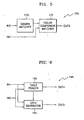
- FIG. 1 is a block diagram of an apparatus for correcting the color of an image, according to a preferred embodiment of the present invention.
- the apparatus includes a user interface 10, a table generator 12, and a color corrector 14.
- the apparatus of FIG. 1 corrects the color of an image displayed on an image display device as follows.
- the image display device refers to a monitor or the like.
- the user interface 10 displays each of N reference patches on the image display device, removes non-gray components from the displayed reference patches depending on the characteristics of a user's visual system, and outputs the reference patches from which the non-gray components have been removed as adjusted reference patches to the table generator 12.
- N is a predetermined positive number greater than equal to "1", where the greater the predetermined positive number, the better.
- the user interface 10 displays a plurality of pairs one by one.
- each of the plurality of pairs includes a reference patch and a background.
- Each background pairing with each reference patch is pre-determined.
- the user interface 10 removes non-gray components from the reference patches of the displayed pairs depending on the characteristics of the user's visual system and matches luminances of the displayed reference patches with luminances of the displayed backgrounds depending on the characteristics of the user's visual system.
- the user interface 10 outputs the reference patches, from which the non-gray components have been removed and the luminances of which have matched with the luminances of the displayed backgrounds, as adjusted reference patches.
- the table generator 12 generates at least one lookup table (LUT) which stores as addresses color component values an image may have and color component values of the adjusted reference patches input from the user interface 10 as data, and outputs the generated at least one LUT to the color corrector 14.
- the color component values may refer to R, G, and B component values.
- the LUTs for storing the R, G, and B component values, respectively, may be generated separately.
- the LUT for the R component stores as addresses R component values the image may have and R component values of the adjusted reference patches as data.
- the color corrector 14 addresses at least one LUT using color component values of an image to be displayed which are input as address of LUT via an input node IN1, reads data corresponding to the color component values from the at least one LUT, and outputs the read data as the result of correcting color of the image to be displayed via an output node OUT1.
- FIG. 2 is a block diagram of the user interface 10 of FIG. 1 , according to a preferred embodiment of the present invention.
- a user interface 10A includes a luminance manipulator 32, a chroma component manipulator 34, and an adjusted reference patch generator 36.
- the luminance manipulator 32 is manipulated by a user, who desires to match the luminances of the displayed reference patches with the luminances of the displayed backgrounds which are a pair with the displayed reference patches, to match the luminances of the displayed reference patches with the luminances of the displayed backgrounds and outputs the manipulation results to the adjusted reference patch generator 36.
- the user manipulates the luminance manipulator 32 to match the luminances of the displayed reference patches with the luminances of the displayed backgrounds based on the characteristics of the user's visual system.
- the chroma component manipulator 34 is manipulated by a user, who desires to remove the non-gray components from the displayed reference patches, to remove the non-gray components from the displayed reference patches and outputs the removal results to the adjusted reference patch generator 36.
- the user manipulates the chroma component manipulator 34 to remove the non-gray components from the displayed reference patches based on the characteristics of the user's visual system.
- the adjusted reference patch generator 36 generates the adjusted reference patches using the reference patches, the luminances of which have been manipulated by the luminance manipulator 32 and from which the non-gray components have been removed by the chroma component manipulator 34, and outputs the adjusted reference patches to the color corrector 14 via an output node OUT2.
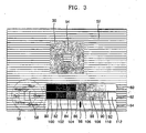
- FIG. 3 is a view for showing the external appearance of the user interface 10 of FIG. 1 , according to a preferred embodiment of the present invention.
- the user interface 10 includes a reference patch 50, a background 52, gray balance cursors 54 and 58, a gray balance guide map 56, a group of reference patches 60, a group of adjusted reference patches 62, and a luminance manipulating portion 64 having a slide bar 66.
- the group of reference patches 60 includes seven reference patches 80 through 92
- the group of adjusted reference patches 62 includes seven adjusted reference patches 100 through 112.
- the gray balance guide map 56 and the gray balance cursors 54 and 58 correspond to the chroma component manipulator 34 of FIG. 2 .
- the gray balance guide map 56 represents designator of a plurality of chroma components in different locations on a two-dimensional space. For example, as shown in FIG. 3 , designators of yellow, red, magenta, blue, cyan; and green may be expressed as "Yellow”, “Red”, “Magenta”, “Blue”, “Cyan”, and “Green".
- the gray balance cursors 54 and 58 are located in the reference patch 50 and the gray balance guide map 56, respectively, and may be manipulated by the user so as to move the same distance at the same time and in the same direction.
- the gray balance cursor 54 in the reference patch 50 also moves the same distance as that by which the gray balance cursor 58 moves, from the time when the gray balance cursor 58 moves, in the left horizontal direction.
- a chroma component designated by the arbitrary designator may be gradually removed from the reference patch 50.
- the chroma component designated by the arbitrary designator may be gradually removed from the reference patch 50.
- the user moves the gray balance cursor 58 in the left horizontal direction toward the christener "Red” until the R component is removed from the reference patch 50.
- the gray balance cursor 58 gets closer to the namer "Red"
- a larger amount of non-gray component i.e., the R component
- the user determines the distance the user moves the gray balance cursor 58 toward a christener, based on the characteristics of the user's visual system.
- the luminance manipulating portion 64 of FIG. 3 corresponds to the luminance manipulator 34 of FIG. 2 .
- the reference patch 50 may become dark or bright according to the left or right movement of the slide bar 66 of the luminance manipulating portion 64.
- the user can horizontally move the slide bar 66 by manipulating the pointing device to match the luminance of the reference patch 50 with the luminance of the background 52.
- the reference patch 50 is displayed to have the same luminance as the selected reference patch.
- the reference patch 50 is displayed to have the same luminance as the reference patch 88.
- the adjustment of the luminance characteristics of the reference patch through the manipulation of the slide bar 66 and the removal of the non-gray components from the reference patch through the manipulation of the gray balance cursor 58 results in obtaining adjusted reference patches for the respective reference patches of the group of reference patches 60.
- the respective adjusted reference patches of the group of adjusted reference patches 62 are the results obtained by adjusting the luminance of the reference patch 50 using the luminance manipulating portion 64 and removing the non-gray component from the reference patch 50 using the gray balance cursor 58.
- the reference patch 88 is selected to display the reference patch 50 as shown in FIG. 3
- the luminance of the reference patch 50 is adjusted by the luminance manipulator 32, and the non-gray component is removed from the reference patch 50 by the chroma component manipulator 34, as shown in FIG. 3
- the adjusted reference patch 108 is generated.
- the user interface 10 of FIG. 3 may not include the group of reference patches 60 and the group of adjusted reference patches 62.
- the user interface 10 is not limited to the case of FIG. 3 .
- the reference patch 50, the gray balance cursors 54 and 58, the group of reference patches 60, the group of adjusted reference patches 62, the slide bar 66, and the gray balance guide map 56 may have various shapes and patterns.
- a pattern of the gray balance cursor 54 in the reference patch 50 may be identical to a pattern of the background 52 so that the user further exactly removes the non-gray component from the reference patch 50.
- respective backgrounds which are displayed to pair with respective reference patches by the user interface 10 of FIG. 1 , may have a pattern in which at least two of black, white, and gray lines cross each other.
- lines in the backgrounds adjacent lines of the same color do not exceed "3". This is because it is difficult to match the luminance of the reference patch with the luminance of the background in view of the characteristics of the user's visual system when more than three lines with the same color are adjacent to one another.
- FIGS. 4A through 4E are views for showing examples of backgrounds.
- reference numbers 130 and 150 denote first and second gray lines, respectively.
- luminances of backgrounds may vary depending on the kind and number of lines included in the backgrounds, i.e., the rates of black, gray, and white lines.
- Table 1 Classification Background Luminance (%) Background Pattern First Background 11.1 Black Line (2), First Gray Line (1) Second Background 33.3 Black Line (2), White Line (1) Third Background 50.0 Black Line (1), White Line (1) Fourth Background 66.7 Black Line (1), White Line (2) Fifth Background 88.9 Second Gray Line (1), White Line (2)
- each of the figures in the parentheses in the column of "Background Pattern” denotes the number of adjacent lines in each background.
- the first, second, third, fourth, and fifth backgrounds correspond to backgrounds shown in FIGS. 4A through 4E, respectively.
- the first gray lines 130 shown in FIG. 4A have the same color component values as color component values of adjusted reference patch that are determined for reference patch displayed together with a background shown in FIG. 4B.
- the adjusted reference patch of the reference patch displayed along with the background of FIG. 4B must be obtained prior to the adjusted reference patch of reference patch displayed together with a background of FIG. 4A.
- the dependency of the color component value of the first gray lines 130 included in the background of FIG. 4A on the adjusted reference patch of the reference patches displayed with the background of FIG. 4B is ascribed to the point that the number of adjacent black lines of FIG. 4B is equal to the number of adjacent black lines of FIG. 4A and the number of lines between the black lines of FIG. 4A is equal to the number of lines between the black lines of FIG. 4B.
- the second gray lines 150 have the same color component values as that of the adjusted reference patch that are determined for reference patch displayed with a background of FIG. 4D.
- the adjusted reference patch of the reference patch displayed together with the background of FIG. 4D must be obtained prior to the adjusted reference patch for reference patch displayed along with a background of FIG. 4E.
- the dependency of the color component value of the second gray lines 150 included in the background of FIG. 4E on the adjusted reference patch of the reference patch displayed together with the background of FIG. 4D is attributed to the point that the number of adjacent black lines of FIG. 4E is equal to the number of adjacent black lines of FIG. 4D and the number of lines between black lines of FIG. 4E is equal to the number of lines between black lines of FIG. 4D.
- FIG. 5 is a block diagram of the table generator 12 of FIG. 1 , according to a preferred embodiment of the present invention.
- a table generator 12A includes a gamma matcher 170 and a color component matcher 172.
- the gamma matcher 170 matches a luminance of each of N backgrounds, which are input from the user interface 10 via an input node IN2, with color component values an image may have using a gamma function and outputs the matching results to the color component matcher 172.
- Y may be normalized as "1 which represents white or as "0" which represents black, and y denotes gamma which may be set to "2.2" on standard RGB (sRGB) color space.
- the component matcher 172 analyzes the matching results input from the gamma matcher 170, matches the color component values the image may have with the color component values of the adjusted reference patch, which are input from the user interface 10 via an input node IN3, and outputs the matching results as at least one LUT via an output node OUT3.
- R, G, and B color component values V an image may have are the same, and R', G', and B' denote R, G, and B color component values of adjusted reference patch, respectively.
- R',G',B' (0, 0, 0) denote color component values of a zero th adjusted reference patch generated for a zero th reference patch pairing with a zero th background.
- R',G',B' (R2, G2, B2) denote color component values of a second adjusted reference patch generated for a second reference patch pairing with a second background.
- R',G',B' (R3, G3, B3) denote color component values of a third adjusted reference patch generated for a third reference patch pairing with a third background.
- R',G',B' (R4, G4, B4) denote color component values of a fourth adjusted reference patch generated for a fourth reference patch pairing with a fourth background.
- R',G',B' (R5, G5, B5) denote color component values of a fifth adjusted reference patch generated for a fifth reference patch pairing with a fifth background.
- R',G',B' (255, 255, 255) denote color component values of a sixth adjusted reference patch generated for a sixth reference patch pairing with a sixth background.
- the gamma matcher 170 of FIG. 5 substitutes the gamma function as in Equation 2 for luminances of seven backgrounds, i.e., zero th through sixth backgrounds, to calculate color component values V as shown in.Table 2.
- the gamma matcher 170 matches luminances of backgrounds with color component values V using a gamma function as shown in Table 2.
- the color component matcher 172 may match color component values R', G', and B' of the adjusted reference patches, which have been obtained for the respective reference patches by the user interface 10, with the color component values V, using the relationship between the luminances of the backgrounds and the color component values V, the relationship being the matching result of the gamma matcher 170.
- the color component matcher 172 receives the first adjusted reference patch for the first reference patch pairing with the first background from the user interface 10.
- the color component matcher 172 extracts color component values R1, G1, and B1 of the first adjusted reference patch, matches the extracted color component values R1, G1, and B1 with color component value "94" matched with the first background by the gamma matcher 170, and generates an LUT which has the color component value "94" as an address and stores the extracted color component values R1, G1, and B1 as data.
- color component values V may be matched with color component values R', G', and B' of the zero th through sixth adjusted reference patches.
- a first LUT is generated using the relationship between the color component values V and the color component values R' as shown in Table 2.
- a second LUT is generated using the relationship between the color component values V and the color component values R' as shown in Table 2.
- a third LUT is generated using the relationship between the color component values V and the color component values B' as shown in Table 2. Accordingly, the color component matcher 172 generates the generated first, second, and third LUTs and outputs the first, second, and third LUTs to the color corrector 14.
- FIG. 6 is a block diagram of the color corrector 14, according to a preferred embodiment of the present invention.
- a color corrector 14A includes a table reader 190 and a data generator 192.
- the table reader 190 receives at least one LUT from the table generator 12 via an input node IN4; addresses the at least one LUT using the color component values of the image to be displayed, which are input as the addresses via an input node IN5, to read data corresponding to the color component values of the image; and outputs the read data as the result of correcting color components of the image to be displayed via an output node OUT4.
- the data generator 192 predicts data corresponding to the color components values of the image using piecewise linear modeling and outputs the prediction results as the result of correcting color of the image via an output node OUT5.
- the data generator 192 may look up the at least LUT input via the input node IN4 to determine that the at least one LUT does not store data corresponding to the color component values of the image. According to another aspect of the present invention, the data generator 192 may determine that the at least one LUT does not store data corresponding to the color components values of the image, in response to a storage determination signal input from the table reader 190. For this purpose, the table reader 190 may output to the data generator 192 the storage determination signal for indicating that at least one LUT does not store data corresponding to the color components values of the image input via the input node IN5.
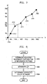
- FIG. 7 is an exemplary graph for showing a first LUT.
- the horizontal axis denotes R component values V an image may have, and the vertical axis denotes R component value R' of adjusted reference patch.
- the horizontal axis corresponds to addresses of the first LUT, and the vertical axis corresponds to data stored in the first LUT.
- the data generator 192 obtains a graph as shown in FIG. 7 using the first LUT input via the input node IN4.
- the data generator 192 marks the relationship between the color component values V and R' stored in the first LUT on the graph of FIG. 7 with dots 210, 212, 214, 216, 218, and 220 and then links the dots 210, 212, 214, 216, 218, and 220 with a straight line.
- the representation of an LUT on a graph and then the link of values which may be perceived through the LUT with a straight line refer to the piecewise linear modeling.
- FIG. 8 is a flowchart for explaining a method of correcting the color of an image, according to a preferred embodiment of the present invention.
- the method includes steps 300 and 302 of obtaining at least one LUT using adjusted reference patches obtained depending on the characteristics of a user's visual system and step 304 of correcting color of an image using the at least one LUT.
- steps 300, 302, and 304 may be performed by the user interface 10, the table generator 12, and the color corrector 14, respectively.
- each of N reference patches is displayed, non-gray components are removed from the displayed N reference patches depending on the characteristics of the user's visual system, and the reference patches from which the non-gray components have been removed are determined as adjusted reference patches.
- step 300 a plurality of pairs of reference patches and backgrounds are displayed pair by pair, non-gray components are removed from the displayed reference patches depending on the characteristics of a user's visual system, luminances of the displayed reference patches are matched with luminances of the displayed backgrounds depending on the characteristics of the user's visual system, and the reference patches from which the non-gray components have been removed and the luminances of which have matched with the luminances of the displayed backgrounds are determined as adjusted reference patches.
- step 302 at least one LUT, which has as addresses color component values an image may have and stores color component values of the adjusted reference patches as data, is generated.
- step 304 at least one LUT is addressed using the color component values of the image to read data corresponding to the color component values of the image and the read data is determined as the result of correcting color of the image.
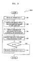
- FIG. 9 is a flowchart for explaining an embodiment 300A of step 300 of FIG. 8 .
- Step 300A includes steps 400, 402, 404, 406, 408, and 410 of obtaining adjusted reference patches for reference patches.
- a variable n is initialized to, for example, "1".
- step 402 a pair of n th reference patch and n th background is displayed.
- step 404 a luminance of the n th reference patch matches with a luminance of the n th background depending on the characteristics of the user's visual system, and an adjusted reference patch is generated based on matching result. For example, a user determines depending on the characteristics of the user's visual system whether the luminance of the n th reference patch seems identical to the luminance of the n th background.
- the user determines that the luminance of the n th reference patch does not seem identical to the luminance of the n th background, the user adjusts the luminance of the n th reference patch so as to match with the luminance of the n th background.
- a non-gray component is removed from the displayed n th reference patch depending on the characteristics of the user's visual system, and an adjusted reference patch is generated based on the removal result. For example, the user determines depending on the characteristics of the user's visual system whether the displayed n th reference patch includes the non-gray component. If the user determines that the displayed n th reference patch includes the non-gray component, the user removes the non-gray component from the n th reference patch until the non-gray component is completely removed from the n th reference patch.
- step 408 a determination is made as to whether the variable n is equal to N. In other words, a determination is made as to whether steps 404 and 406 have been completely performed on all of reference patches.
- step 408 If in step 408, it is determined that the variable n is equal to N, the process moves on to step 302 to generate an LUT. If in step 408, it is determined that the variable n is not equal to N, in step 410, the variable n increases by "1 " and the process returns to step 402.
- step 300A of FIG. 9 may not include step 404.
- step 406 is performed after step 402.
- step 404 of FIG. 9 may be performed not between steps 402 and 406 but between steps 406 and 408.
- step 406 is performed after step 402
- step 404 is performed after step 406, and step 408 is performed after step 404.
- the above-described image color-correcting apparatus and method according to the present invention can be adopted to edit an image displayed on an image display device.
- the luminance characteristics of an image display device can be corrected depending on the characteristics of a user's visual system without using a high-priced colorimetric apparatus.
- non-gray components which may be generated during the reproduction of a black and white image, can be removed.
- a user interface screen as shown in FIG. 3 a user can relatively easily adjust a reference patch depending on the characteristics of the user's visual system. As a result, the user can conveniently correct the color of an image to be displayed.
Landscapes
- Engineering & Computer Science (AREA)
- General Physics & Mathematics (AREA)
- Physics & Mathematics (AREA)
- Signal Processing (AREA)
- Theoretical Computer Science (AREA)
- Multimedia (AREA)
- Computer Hardware Design (AREA)
- Business, Economics & Management (AREA)
- Emergency Management (AREA)
- Human Computer Interaction (AREA)
- Computer Networks & Wireless Communication (AREA)
- Image Processing (AREA)
- Facsimile Image Signal Circuits (AREA)
- Processing Of Color Television Signals (AREA)
- Controls And Circuits For Display Device (AREA)
- Color Image Communication Systems (AREA)
Claims (12)
- Vorrichtung zum Korrigieren der Farbe eines Bildes, das auf einer Bildanzeigevorrichtung anzuzeigen ist, wobei die Vorrichtung umfasst:eine Benutzerschnittstelle (10), die dazu ausgebildet ist, jedes von N (das eine vorgegebene positive Zahl größer oder gleich "1" darstellt) Referenzpatches anzuzeigen, in Abhängigkeit von Charakteristiken eines Betrachtungssystems eines Benutzers, die vom Benutzer eingegeben sind, Nichtgraukomponenten aus dem angezeigten Referenzpatch zu eliminieren und die Referenzpatches, aus denen die Nichtgraukomponenten eliminiert worden sind, als angepasste Referenzpatches auszugebenwobei eine Struktur von Graubalanceanzeigern (54) in den Referenzpatches (50) zu einer Struktur von Hintergründen identisch ist, die an die Referenzpatches angrenzen,einen Tabellengenerator (12), der dazu ausgebildet ist, mindestens eine Nachschlagetabelle zu erzeugen, die als Adressen Farbkomponentenwerte enthält, die das Bild aufweisen kann, und Farbkomponentenwerte der angepassten Referenzpatches als Daten zu speichern, undeine Farbkorrektureinrichtung (14), die die mindestens eine Nachschlagetabelle unter Verwendung der Farbkomponentenwerte des Bildes zum Lesen von Daten adressiert, die den Farbkomponentenwerten des Bildes zugeordnet sind, und die gelesenen Daten als Ergebnis einer Korrektur der Farbe des Bildes ausgibt,und dadurch gekennzeichnet, dass die Hintergründe (52) und die Anzeiger (54) eine Struktur von Linien aufweisen, die vom Betrachtungssystem des Benutzers in ein gleichmäßiges Grau mit einer gegebenen Luminanz verzerrt wird.
- Vorrichtung nach Anspruch 1, wobei die Benutzerschnittstelle dazu ausgebildet ist, eine Mehrzahl von Paaren von Referenzpatches und Hintergründen paarweise anzuzeigen, Nichtgraukomponenten aus den angezeigten Referenzpatches in Abhängigkeit von den Charakteristiken des Betrachtungssystems des Benutzers zu eliminieren, Luminanzen der angezeigten Referenzpatches, mit Luminanzen der angezeigten Hintergründe in Abhängigkeit von den Charakteristiken des Betrachtungssystems des Benutzers abzugleichen und die Referenzpatches, aus denen die Nichtgraukomponenten eliminiert worden sind und deren Luminanzen mit den Luminanzen der Hintergründe abgeglichen worden sind, als die angepassten Referenzpatches auszugeben, wobei jedes der Mehrzahl von Paaren ein Referenzpatch und einen Hintergrund umfasst und die Hintergründe, die sich mit den Referenzpatches paaren, vorgegeben werden.
- Vorrichtung nach Anspruch 2, wobei die Benutzerschnittstelle umfasst:einen Luminanzmanipulator (32), der dazu ausgebildet ist, dass er vom Benutzer betätigt wird, der die Luminanz des angezeigten Referenzpatch mit der Luminanz des angezeigten Hintergrunds, der ein Paar mit dem angezeigten Referenzpatch bildet, abzugleichen wünscht,einen Farbkomponentenmanipulator (34), der dazu ausgebildet ist, dass er vom Benutzer betätigt wird, der die Nichtgraukomponenten aus den angezeigten Referenzpatches zu eliminieren wünscht, undeinen Generator (36) für angepasste Referenzpatches, der dazu ausgebildet ist, die angepassten Referenzpatches für die Referenzpatches unter Verwendung der Manipulationsergebnisse zu erzeugen, die vom Luminanzmanipulator und dem Farbkomponentenmanipulator erhalten sind.
- Vorrichtung nach Anspruch 3, wobei der Farbkomponentenmanipulator umfasst:eine Graubalance-Orientierungskarte (56), die dazu ausgebildet ist, Bezeichner einer Mehrzahl von Chrominanzkomponenten an unterschiedlichen Stellen in einem zweidimensionalen Raum darzustellen, undGraubalanceanzeiger (54, 58), die in den Referenzpatches (50) und der Graubalance-Orientierungskarte (56) vorgesehen sind und dazu ausgebildet sind, dass sie vom Benutzer so betätigt werden, dass sie sich gemeinsam um eine identische Distanz in eine identische Richtung bewegen,wobei, während der Graubalanceanzeiger (58) in der Graubalance-Orientierungskarte (56) einem beliebigen Bezeichner näher kommt, eine von dem beliebigen Bezeichner bezeichnete Chrominanzkomponente schrittweise aus den Referenzpatches eliminiert wird.
- Vorrichtung nach einem der Ansprüche 1 bis 4, wobei die Hintergründe eine Struktur aufweisen, in der mindestens zwei von schwarzen, weißen und grauen Linien einander benachbart sind.
- Vorrichtung nach Anspruch 5, wobei im Hintergrund die Anzahl an benachbarten Linien mit der gleichen Farbe nicht mehr als "3" beträgt.
- Vorrichtung nach einem der Ansprüche 1 bis 6, wobei der Tabellengenerator umfasst:einen Gamma-Matcher (170), der dazu ausgebildet ist, die Luminanzen der N Hintergründe mit den Farbkomponentenwerten, die das Bild aufweisen kann, unter Verwendung einer Gamma-Funktion abzugleichen, undeinen Farbkomponenten-Matcher (172), der dazu ausgebildet ist, die Abgleichungsergebnisse zu analysieren, die Farbkomponentenwerte, die das Bild aufweisen kann, mit den Farbkomponentenwerten der angepassten Referenzpatches abzugleichen und die Abgleichungsergebnisse als mindestens eine Nachschlagetabelle auszugeben.
- Vorrichtung nach einem der vorhergehenden Ansprüche, wobei die Farbkorrektureinrichtung umfasst:einen Tabellenleser (190), der dazu ausgebildet ist, die mindestens eine Nachschlagetabelle unter Verwendung der Farbkomponentenwerte des Bildes zu adressieren, um die den Farbkomponentenwerten des Bildes zugeordneten Daten zu lesen und die gelesenen Daten als das Ergebnis einer Korrektur der Farbe des Bildes auszugeben, undeinen Datengenerator (192), der dazu ausgebildet ist, die Daten, wenn die mindestens eine Nachschlagetabelle keine Daten speichert, die den Farbkomponentenwerten des Bildes zugeordnet sind, unter Verwendung stückweiser Linearmodellierung vorherzusagen und die Vorhersageergebnisse als das Ergebnis einer Korrektur der Farbe des Bildes auszugeben.
- Verfahren zum Korrigieren der Farbe eines Bildes, das auf einer Bildanzeigevorrichtung anzuzeigen ist, wobei das Verfahren umfasst:Anzeigen jedes von N (das eine vorgegebene positive Zahl größer oder gleich "1" darstellt) Referenzpatches, Eliminieren von Nichtgraukomponenten aus den Referenzpatches in Abhängigkeit von den Charakteristiken eines Betrachtungssystems eines Benutzers, die vom Benutzer eingegeben sind, und Bestimmen der Referenzpatches, aus denen die Nichtgraukomponenten eliminiert worden sind, als angepasste Referenzpatches,wobei eine Struktur von Graubalanceanzeigern (54) in den Referenzpatches (50) zu einer Struktur von Hintergründen identisch ist, die an die Referenzpatches angrenzen,Erzeugen mindestens einer Nachschlagetabelle, die als Adressen Farbkomponentenwerte enthält, die das Bild aufweisen kann, und Farbkomponentenwerte der angepassten Referenzpatches als Daten speichert, undAdressieren der mindestens einen Nachschlagetabelle unter Verwendung der Farbkomponentenwerte des Bildes zum Lesen von Daten, die den Farbkomponentenwerten des Bildes zugeordnet sind, und Bestimmen der gelesenen Daten als Ergebnis einer Korrektur der Farbe des Bildes,und dadurch gekennzeichnet, dass die Hintergründe (52) und die Anzeiger (54) eine Struktur von Linien aufweisen, die vom Betrachtungssystem des Benutzers in ein gleichmäßiges Grau mit einer gegebenen Luminanz verzerrt werden.
- Verfahren nach Anspruch 9, wobei eine Mehrzahl von Paaren von Referenzpatches und Hintergründen paarweise angezeigt werden, Nichtgraukomponenten aus den angezeigten Referenzpatches in Abhängigkeit von den Charakteristiken des Betrachtungssystems des Benutzers eliminiert werden, Luminanzen der angezeigten Referenzpatches mit Luminanzen der angezeigten Hintergründe in Abhängigkeit von den Charakteristiken des Betrachtungssystems des Benutzers abgeglichen werden und die Referenzpatches, aus denen die Nichtgraukomponenten eliminiert worden sind und deren Luminanzen mit den Luminanzen der Hintergründe abgeglichen worden sind, als die angepassten Referenzpatches bestimmt werden, wobei jedes der Mehrzahl von Paaren ein Referenzpatch und einen Hintergrund umfasst und die Hintergründe, die sich mit den Referenzpatches paaren, vorgegeben sind.
- Verfahren nach Anspruch 10, wobei die Bestimmung der angepassten Referenzpatches umfasst:Initialisieren einer Variable n,Anzeigen eines n-ten Referenzpatch und eines n-ten Hintergrunds, die ein Paar bilden, gemeinsam,Eliminieren der Nichtgraukomponente aus dem angezeigten n-ten Referenzpatch in Abhängigkeit von den Charakteristiken des Betrachtungssystems des Benutzers,Bestimmen, ob die Variable n gleich N ist, und wenn bestimmt ist, dass die Variable n gleich N ist, weiter zum Erzeugen der mindestens einen Nachschlagetabelle undwenn bestimmt ist, dass die Variable n nicht gleich N ist, Erhöhen der Variable n um "1" und zurück zum Anzeigen des n-ten Referenzpatch und des n-ten Hintergrunds.
- Verfahren nach Anspruch 11, wobei die Bestimmung der angepassten Referenzpatches weiter umfasst:Abgleichen einer Luminanz des n-ten Referenzpatch mit einer Luminanz des n-ten Hintergrunds in Abhängigkeit von den Charakteristiken des Betrachtungssystems des Benutzers.
Applications Claiming Priority (2)
| Application Number | Priority Date | Filing Date | Title |
|---|---|---|---|
| KR1020040021818A KR100601947B1 (ko) | 2004-03-30 | 2004-03-30 | 영상의 색 보정 장치 및 방법 |
| KR2004021818 | 2004-03-30 |
Publications (3)
| Publication Number | Publication Date |
|---|---|
| EP1600894A2 EP1600894A2 (de) | 2005-11-30 |
| EP1600894A3 EP1600894A3 (de) | 2008-04-02 |
| EP1600894B1 true EP1600894B1 (de) | 2010-12-29 |
Family
ID=34940644
Family Applications (1)
| Application Number | Title | Priority Date | Filing Date |
|---|---|---|---|
| EP05251888A Expired - Lifetime EP1600894B1 (de) | 2004-03-30 | 2005-03-24 | Apparat und Verfahren zum Korrigieren der Farbe eines Bildes |
Country Status (5)
| Country | Link |
|---|---|
| US (1) | US7688326B2 (de) |
| EP (1) | EP1600894B1 (de) |
| JP (1) | JP4991120B2 (de) |
| KR (1) | KR100601947B1 (de) |
| DE (1) | DE602005025561D1 (de) |
Families Citing this family (12)
| Publication number | Priority date | Publication date | Assignee | Title |
|---|---|---|---|---|
| KR100837744B1 (ko) | 2005-08-10 | 2008-06-13 | 세이코 엡슨 가부시키가이샤 | 화상 표시 장치 및 그 화상 조정 방법 |
| JP2007156215A (ja) * | 2005-12-07 | 2007-06-21 | Matsushita Electric Ind Co Ltd | ディスプレイ装置 |
| JP2007205804A (ja) * | 2006-01-31 | 2007-08-16 | Canon Inc | 表示装置、表示方法および制御プログラム |
| JP2007208529A (ja) * | 2006-01-31 | 2007-08-16 | Canon Inc | 表示制御装置、表示制御方法および制御プログラム |
| KR101232177B1 (ko) * | 2006-11-27 | 2013-02-12 | 엘지디스플레이 주식회사 | 평판표시장치의 선 결함 보상방법 및 장치 |
| KR101348369B1 (ko) | 2007-11-12 | 2014-01-07 | 삼성전자주식회사 | 디스플레이 장치의 색 변환 방법 및 장치 |
| US8130240B2 (en) | 2008-10-24 | 2012-03-06 | Microsoft Corporation | Target display for gamma calibration |
| US8503776B2 (en) | 2009-10-09 | 2013-08-06 | Electronics And Telecommunications Research Institute | Apparatus and method for providing display information for color calibration of display device |
| KR101324090B1 (ko) * | 2009-10-09 | 2013-10-31 | 한국전자통신연구원 | 디스플레이 기기의 색 캘리브레이션을 위한 디스플레이 정보 제공 장치 및 방법 |
| EP2573671A2 (de) * | 2011-09-26 | 2013-03-27 | Samsung Electronics Co., Ltd | Farbkalibrierverfahren und -vorrichtung |
| US20140168253A1 (en) * | 2012-12-18 | 2014-06-19 | Canon Kabushiki Kaisha | Color processing apparatus and method |
| KR102617938B1 (ko) * | 2016-08-23 | 2023-12-27 | 삼성디스플레이 주식회사 | 표시 장치의 구동 방법 및 이를 수행하는 표시 장치 |
Family Cites Families (16)
| Publication number | Priority date | Publication date | Assignee | Title |
|---|---|---|---|---|
| US5334992A (en) * | 1987-10-26 | 1994-08-02 | Tektronix, Inc. | Computer display color control and selection system |
| US5483259A (en) * | 1994-04-12 | 1996-01-09 | Digital Light & Color Inc. | Color calibration of display devices |
| US5754222A (en) * | 1996-03-08 | 1998-05-19 | Eastman Kodak Company | Visual characterization using display model |
| JPH11252589A (ja) * | 1998-03-03 | 1999-09-17 | Dainippon Printing Co Ltd | モニタの色調調整方法及びそれに用いる調整用カラーチャート |
| US6023264A (en) * | 1998-04-24 | 2000-02-08 | Adobe Systems Incorporated | Method to estimate the white point on a display device |
| US6078309A (en) * | 1998-05-22 | 2000-06-20 | Way Tech Development, Inc. | System and method for visually measuring color characteristics of a display |
| JP3678000B2 (ja) | 1998-05-27 | 2005-08-03 | 富士通株式会社 | 表示装置の調整方法及び表示装置の調整装置 |
| US6233560B1 (en) | 1998-12-16 | 2001-05-15 | International Business Machines Corporation | Method and apparatus for presenting proximal feedback in voice command systems |
| US6686953B1 (en) * | 2000-03-01 | 2004-02-03 | Joseph Holmes | Visual calibration target set method |
| US7119760B2 (en) * | 2000-03-31 | 2006-10-10 | Kodak Graphic Communications Canada Company | Color image display accuracy using green-limited gamma estimate |
| US20040227769A9 (en) * | 2000-03-31 | 2004-11-18 | Imation Corp. | Color image display accuracy using comparison of colored objects to dithered background |
| JP2003534723A (ja) * | 2000-05-24 | 2003-11-18 | コピン・コーポレーシヨン | 携帯用マイクロディスプレイ・システム |
| JP2002055668A (ja) * | 2000-08-10 | 2002-02-20 | Sharp Corp | 表示装置の入出力特性測定方法、表示装置の画像補正方法、表示装置のiccプロファイル作成方法およびそれらの方法の手順を記憶した記憶媒体並びに表示装置 |
| JP2003052057A (ja) * | 2001-08-08 | 2003-02-21 | Hitachi Ltd | 映像変換による立体視映像生成装置 |
| US6919905B2 (en) * | 2001-09-28 | 2005-07-19 | Hewlett-Packard Development Company, L.P. | Method and device for visual calibration of displays |
| US7215813B2 (en) * | 2001-12-03 | 2007-05-08 | Apple Computer, Inc. | Method and apparatus for color correction |
-
2004
- 2004-03-30 KR KR1020040021818A patent/KR100601947B1/ko not_active Expired - Fee Related
-
2005
- 2005-03-24 EP EP05251888A patent/EP1600894B1/de not_active Expired - Lifetime
- 2005-03-24 DE DE602005025561T patent/DE602005025561D1/de not_active Expired - Lifetime
- 2005-03-30 US US11/093,258 patent/US7688326B2/en not_active Expired - Fee Related
- 2005-03-30 JP JP2005097799A patent/JP4991120B2/ja not_active Expired - Fee Related
Also Published As
| Publication number | Publication date |
|---|---|
| US20050231741A1 (en) | 2005-10-20 |
| KR100601947B1 (ko) | 2006-07-14 |
| JP2005284292A (ja) | 2005-10-13 |
| EP1600894A2 (de) | 2005-11-30 |
| JP4991120B2 (ja) | 2012-08-01 |
| EP1600894A3 (de) | 2008-04-02 |
| US7688326B2 (en) | 2010-03-30 |
| DE602005025561D1 (de) | 2011-02-10 |
| KR20050097091A (ko) | 2005-10-07 |
Similar Documents
| Publication | Publication Date | Title |
|---|---|---|
| US6724435B2 (en) | Method for independently controlling hue or saturation of individual colors in a real time digital video image | |
| US6594387B1 (en) | Enhanced color correction | |
| EP2122579B1 (de) | Anaglyphen mit breiter farbskala | |
| KR101348369B1 (ko) | 디스플레이 장치의 색 변환 방법 및 장치 | |
| EP1600894B1 (de) | Apparat und Verfahren zum Korrigieren der Farbe eines Bildes | |
| EP0488656A2 (de) | Farbtransformationsverfahren | |
| JPH10145582A (ja) | 画像処理方法及び装置 | |
| EP1898624B1 (de) | Bildverarbeitungseinrichtung, bildverarbeitungsverfahren, bildverarbeitungs-programmprodukt und bildgebungseinrichtung | |
| EP1770999A2 (de) | Verfahren und Vorrichtung zur Bildkompensation | |
| KR101090060B1 (ko) | 그레이 이미지의 보정이 가능한 화상형성장치 및화상형성방법 | |
| US5982992A (en) | Error diffusion in color printing where an intra-gamut colorant is available | |
| US7450183B2 (en) | Method and apparatus for compensating for luminance of color signal | |
| US7999826B2 (en) | Color conversion device, color conversion method, color conversion program, recording medium recording color conversion program, image processing device, and image display device | |
| JP2008508768A (ja) | 飽和制御されたカラー画像の色相の維持 | |
| KR20070032999A (ko) | 컬러 포화 제어된 컬러 이미지에서의 컬러 최대값의 유지 | |
| KR20100061389A (ko) | 색 영역 확대 방법 및 표시 장치 | |
| KR20030089632A (ko) | 화상 처리 장치 | |
| KR100565266B1 (ko) | 엘시디의 구간별 색온도 감마 보정방법 | |
| RU2353971C2 (ru) | Схема цветокоррекции по каждому оттенку | |
| US7312799B2 (en) | Visual determination of gamma for softcopy display | |
| US20060170995A1 (en) | Color image correction processing apparatus and color image correction processing method | |
| JP4069860B2 (ja) | 色変換装置および色変換方法 | |
| JP2003299118A (ja) | ディスプレイ装置の画質補正回路 | |
| JP3736648B2 (ja) | 色変換方法および装置 | |
| JP5311443B2 (ja) | カラー映像表示装置とモノクロ映像表示方法 |
Legal Events
| Date | Code | Title | Description |
|---|---|---|---|
| PUAI | Public reference made under article 153(3) epc to a published international application that has entered the european phase |
Free format text: ORIGINAL CODE: 0009012 |
|
| AK | Designated contracting states |
Kind code of ref document: A2 Designated state(s): AT BE BG CH CY CZ DE DK EE ES FI FR GB GR HU IE IS IT LI LT LU MC NL PL PT RO SE SI SK TR |
|
| AX | Request for extension of the european patent |
Extension state: AL BA HR LV MK YU |
|
| RIN1 | Information on inventor provided before grant (corrected) |
Inventor name: KIM, CHANGYEONG502-1305 JINSAN MAEUL Inventor name: CHOE, WONHEE Inventor name: CHO, CHEONYONG Inventor name: CHO, MINKI Inventor name: OK, HYUNWOOKC/O SAMSUNG ADVANCED INST. OF TECH. Inventor name: PARK, DUSIK301-1804 CHEONGMYEONG MAEUL DAWOO APT. Inventor name: LEE, SEONGDEOK435-1504 CHEONGMYEONG MAEUL Inventor name: KIM, DAEWON110-301 HYUNDAI BAEKJO TOWN APT. Inventor name: LEE, HOYOUNG |
|
| PUAL | Search report despatched |
Free format text: ORIGINAL CODE: 0009013 |
|
| AK | Designated contracting states |
Kind code of ref document: A3 Designated state(s): AT BE BG CH CY CZ DE DK EE ES FI FR GB GR HU IE IS IT LI LT LU MC NL PL PT RO SE SI SK TR |
|
| AX | Request for extension of the european patent |
Extension state: AL BA HR LV MK YU |
|
| RIC1 | Information provided on ipc code assigned before grant |
Ipc: H04N 9/73 20060101ALI20080227BHEP Ipc: H04N 17/02 20060101ALI20080227BHEP Ipc: H04N 1/60 20060101ALI20080227BHEP Ipc: G06T 11/00 20060101AFI20050930BHEP |
|
| 17P | Request for examination filed |
Effective date: 20080924 |
|
| 17Q | First examination report despatched |
Effective date: 20081024 |
|
| AKX | Designation fees paid |
Designated state(s): DE FR GB NL |
|
| GRAP | Despatch of communication of intention to grant a patent |
Free format text: ORIGINAL CODE: EPIDOSNIGR1 |
|
| GRAS | Grant fee paid |
Free format text: ORIGINAL CODE: EPIDOSNIGR3 |
|
| GRAA | (expected) grant |
Free format text: ORIGINAL CODE: 0009210 |
|
| AK | Designated contracting states |
Kind code of ref document: B1 Designated state(s): DE FR GB NL |
|
| REG | Reference to a national code |
Ref country code: GB Ref legal event code: FG4D |
|
| REF | Corresponds to: |
Ref document number: 602005025561 Country of ref document: DE Date of ref document: 20110210 Kind code of ref document: P |
|
| REG | Reference to a national code |
Ref country code: DE Ref legal event code: R096 Ref document number: 602005025561 Country of ref document: DE Effective date: 20110210 |
|
| REG | Reference to a national code |
Ref country code: NL Ref legal event code: T3 |
|
| PLBE | No opposition filed within time limit |
Free format text: ORIGINAL CODE: 0009261 |
|
| STAA | Information on the status of an ep patent application or granted ep patent |
Free format text: STATUS: NO OPPOSITION FILED WITHIN TIME LIMIT |
|
| 26N | No opposition filed |
Effective date: 20110930 |
|
| REG | Reference to a national code |
Ref country code: DE Ref legal event code: R097 Ref document number: 602005025561 Country of ref document: DE Effective date: 20110930 |
|
| REG | Reference to a national code |
Ref country code: FR Ref legal event code: PLFP Year of fee payment: 12 |
|
| REG | Reference to a national code |
Ref country code: FR Ref legal event code: PLFP Year of fee payment: 13 |
|
| REG | Reference to a national code |
Ref country code: FR Ref legal event code: PLFP Year of fee payment: 14 |
|
| PGFP | Annual fee paid to national office [announced via postgrant information from national office to epo] |
Ref country code: DE Payment date: 20200310 Year of fee payment: 16 Ref country code: GB Payment date: 20200311 Year of fee payment: 16 Ref country code: NL Payment date: 20200312 Year of fee payment: 16 |
|
| PGFP | Annual fee paid to national office [announced via postgrant information from national office to epo] |
Ref country code: FR Payment date: 20200227 Year of fee payment: 16 |
|
| REG | Reference to a national code |
Ref country code: DE Ref legal event code: R119 Ref document number: 602005025561 Country of ref document: DE |
|
| REG | Reference to a national code |
Ref country code: NL Ref legal event code: MM Effective date: 20210401 |
|
| GBPC | Gb: european patent ceased through non-payment of renewal fee |
Effective date: 20210324 |
|
| PG25 | Lapsed in a contracting state [announced via postgrant information from national office to epo] |
Ref country code: NL Free format text: LAPSE BECAUSE OF NON-PAYMENT OF DUE FEES Effective date: 20210401 Ref country code: FR Free format text: LAPSE BECAUSE OF NON-PAYMENT OF DUE FEES Effective date: 20210331 Ref country code: GB Free format text: LAPSE BECAUSE OF NON-PAYMENT OF DUE FEES Effective date: 20210324 Ref country code: DE Free format text: LAPSE BECAUSE OF NON-PAYMENT OF DUE FEES Effective date: 20211001 |