EP1600756A1 - Crashsimulationsanlage für Kraftfahrfzeuge - Google Patents
Crashsimulationsanlage für Kraftfahrfzeuge Download PDFInfo
- Publication number
- EP1600756A1 EP1600756A1 EP05006082A EP05006082A EP1600756A1 EP 1600756 A1 EP1600756 A1 EP 1600756A1 EP 05006082 A EP05006082 A EP 05006082A EP 05006082 A EP05006082 A EP 05006082A EP 1600756 A1 EP1600756 A1 EP 1600756A1
- Authority
- EP
- European Patent Office
- Prior art keywords
- carriage
- vehicle
- barrier
- simulation system
- motor vehicles
- Prior art date
- Legal status (The legal status is an assumption and is not a legal conclusion. Google has not performed a legal analysis and makes no representation as to the accuracy of the status listed.)
- Granted
Links
- 230000004888 barrier function Effects 0.000 claims abstract description 98
- 238000004088 simulation Methods 0.000 claims abstract description 45
- 230000008878 coupling Effects 0.000 claims description 84
- 238000010168 coupling process Methods 0.000 claims description 84
- 238000005859 coupling reaction Methods 0.000 claims description 84
- 230000001133 acceleration Effects 0.000 claims description 34
- 230000003111 delayed effect Effects 0.000 claims description 4
- 238000012360 testing method Methods 0.000 description 25
- 238000013461 design Methods 0.000 description 7
- 230000001419 dependent effect Effects 0.000 description 3
- 238000011161 development Methods 0.000 description 3
- 230000000694 effects Effects 0.000 description 2
- 230000005484 gravity Effects 0.000 description 2
- 241001295925 Gegenes Species 0.000 description 1
- 238000002474 experimental method Methods 0.000 description 1
- 210000003746 feather Anatomy 0.000 description 1
- 238000013507 mapping Methods 0.000 description 1
- 238000005259 measurement Methods 0.000 description 1
- 230000006641 stabilisation Effects 0.000 description 1
- 238000011105 stabilization Methods 0.000 description 1
Images


Classifications
-
- G—PHYSICS
- G01—MEASURING; TESTING
- G01M—TESTING STATIC OR DYNAMIC BALANCE OF MACHINES OR STRUCTURES; TESTING OF STRUCTURES OR APPARATUS, NOT OTHERWISE PROVIDED FOR
- G01M17/00—Testing of vehicles
- G01M17/007—Wheeled or endless-tracked vehicles
- G01M17/0078—Shock-testing of vehicles
Definitions
- the invention relates to a crash simulation system for motor vehicles according to the preamble of claim 1.
- crash test systems in which a vehicle is driven at a defined speed against a fixed barrier. From the resulting deformation of the vehicle in the experiment and the deformation of the dolls arranged in the interior, so-called dummies, and from the occurring forces and acceleration values, data can be obtained describing the effects of accidents on the vehicle and occupants.
- crash tests are well known and an important part of the testing and development of vehicles in terms of vehicle safety. Both frontal crash tests (impact on a barrier perpendicular to the vehicle direction) and crash tests at a prescribed angle, preferably 30 ° deviation of the barrier from the vertical to the vehicle movement direction, are thereby carried out.
- Crash tests with real vehicles are very cost-intensive and expensive, since the respective vehicle is at least partially deformed, as well as sensors arranged therein and parts of the measurement setup can not be reused.
- vehicles or parts thereof are placed on a movable carriage, which is strongly accelerated or decelerated. In this case, strong acceleration or deceleration forces act on the vehicle fixedly arranged on the carriage.
- the drive of the carriage or its braking device is designed so that real, occurring in accident situations or vehicle crash acceleration values can be achieved or reproduced.
- the described crash simulation is particularly useful for the design of the interior of a vehicle and the effects on the occupants.
- the advantage is the repeatability with largely identical test setup and the cost savings, since a modified vehicle or the test setup can be largely reused.
- DE 195 11 422 A1 shows a crash test system in which a vehicle permanently mounted on a slide is accelerated or braked with respect to its acceleration by a hydraulic drive. The vehicle is fixedly arranged on the carriage. Such designs only insufficiently depict the real crash behavior. Movements of the vehicle during real accident situations z. B. Nick movements about the vehicle transverse axis can not be realized with this structure.
- the invention is therefore based on the object, a crash simulation system for To make motor vehicles such that with a simple structure a reproducible Realistic crash behavior can be simulated, in which both Nick and Rotational movements can be mapped.
- the crash simulation system for motor vehicles consists of a slide movable on a track, to which a vehicle or the parts of a vehicle are directly or indirectly coupled.
- the vehicle may in this case preferably be cut off at the front, so that only parts of the vehicle are arranged on the carriage. However, it is also possible to position the entire vehicle on the carriage.
- the carriage can be additionally guided on the web and is moved by a drive and / or braking device. About the drive and / or braking device can be acted upon on the carriage, so that desired speed or acceleration profiles can be generated.
- the acceleration to drive or braking the carriage can be done permanently or as a pulse.
- Driving into a braking device or accelerating into a catapulting device are just as possible as the controlled drive or braking of the carriage itself.
- the vehicle parts which are held directly or indirectly by the carriage are supported on a barrier firmly coupled to the carriage.
- the support point is not rigidly connected to this with respect to its relative position on the barrier. According to the invention, a change in the relative position of the support point to the barrier during the crash test is made possible.
- the support of the carriage according to the invention allows a flexible structure of the sled.
- the barrier on the slide allows frontal crash tests and crash tests that occur at a certain angle to the barrier, close to reality be reproduced.
- the barrier points towards the direction of movement of the Sliding in horizontal plane at an angle different from 90 °. So-called 30 ° crash tests are by an appropriate adjustment of the barrier (60 ° angle of the barrier relative to the direction of movement of the carriage in a horizontal plane) feasible.
- the barrier is adjustable in angle and thus can be adjusted before the crash test. She will then for the respective Test again firmly connected to the carriage.
- the arrangement of the barrier in an angle different from 90 ° with respect to the Direction of movement of the carriage in a horizontal plane allows close to reality Crash tests, as the vehicle similar to the real accident situation straight to the obstacle is accelerated and then slides off according to the set angle.
- One Turning away the vehicle at the barrier can thus be out of the straight direction of movement be simulated out.
- the support according to the invention allows the variable support point a Realistic movement of the vehicle or arranged on the carriage Car parts. It can both pitching movements about the vehicle transverse axis as well Rotational movements take place about a vertical axis defined by the vehicle. Any Combinations of these movements are also possible.
- the movement or the acting accelerations are very realistic, since a movement of the Support at the barrier according to the driven acceleration / deceleration automatically according to a real accident situation.
- the barrier can have an angle with respect to the direction of travel of the carriage in the vertical plane which differs from 90 °.
- the barrier promotes the pitching movement of the vehicle about its transverse axis and thus simulates a real accident behavior very well.
- the vehicle or the vehicle parts arranged on the carriage are firmly connected to a coupling element.
- the coupling element is supported by a fixedly connected to this support element on the barrier, which is not rigidly connected to the barrier and thus allows the possibility of relative movement of the vehicle to the barrier.
- the coupling element firmly connected to the vehicle relative to the support element in its angular position is changed, so that a relative movement of the coupling element firmly connected to the vehicle barrier is made possible, wherein the support element with its barrier facing surface remains applied to this
- the coupling element and the support element may consist of a unit in a further embodiment of the invention.
- the holder is possible in a so-called ball joint, which allows an angular offset of the coupling element relative to the support element in the horizontal and vertical plane.
- a pivoting of the coupling element to the support element is possible in any direction of movement.
- the vehicle can accordingly move according to the real accident behavior according to the applied accelerations, its center of gravity and the support position of the support at the barrier.
- the support element consists of a coupling rod and a coupling pad. These can be connected to each other via the above-described ball joint, so that the above-described angular offset of the coupling element relative to the support element in the horizontal and / or vertical plane is possible, coupling rod and coupling pad remain connected.
- the coupling pad can be guided in a vertical groove in the barrier and thus allow pitching movements about the vehicle transverse axis.
- Vehicle For the adjustment of realistic parameters of the relative movement between the Barrier and held on the barrier via the coupling and / or support element Vehicle is the resistance, the coupling and / or support element of the relative movement oppose, adjustable.
- This can according to the invention by the targeted design of the Surface pairing of coupling pad and barrier and / or the targeted design of Surface pairing of coupling rod and coupling pad done.
- Another Embodiment is the use of a respect to its resistance to movement adjustable joint between coupling pad and coupling rod.
- the support point of the vehicle at the barrier is advantageous the center of gravity of the vehicle adjustable.
- the location of the support point in relation to The center of mass of the vehicle determines the trajectory of the vehicle.
- the vehicle arranged on the carriage or the vehicle parts are elastically supported against the carriage.
- this can be done by at least one spring.
- the spring can only act as a support between the carriage and the vehicle and can only be attached to the carriage or vehicle on one side.
- the spring or a similar elastically acting element is held on the carriage and vehicle.
- the design of the spring influences the movement path of the vehicle during acceleration or deceleration. According to the acceleration and applied supporting force, a pitching movement of the vehicle is carried out, which is supported against the barrier, wherein the contact point of the support element changes at the barrier on this.
- the springs may also be formed by the vehicle's own springs in a further embodiment of the invention.
- the vehicle is supported on a fixed the support connected to the carriage.
- the support is also designed here that a sliding along the vehicle or from the front of the support element can.
- a sliding along the vehicle or from the front of the support element can.
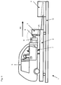
- FIG. 1 the schematic representation of the crash simulation system 1 according to the invention is shown in a side view.
- a vehicle 3 or as shown a part of a vehicle 3 are arranged on a carriage 2 and via a coupling element 6, which is fixedly connected to the vehicle and a support element 8 supported on a barrier 5.
- the support element 8 can slide along the barrier 5 at least in the vertical direction.
- the illustrated arrow P1 symbolizes this movement.
- the barrier 5 is fixedly coupled to the carriage 2 and may also be designed as part of the carriage 2. In one possible embodiment, it is arranged in its angle in the horizontal and / or vertical plane to the carriage 2 adjustable or inclined.
- the carriage 2 is movable on the crash test system 1 and can be performed for tracking stabilization on this.
- the crash test facility 1 is equipped with a braking and / or acceleration unit which can accelerate and / or decelerate the carriage.
- a braking and / or acceleration unit which can accelerate and / or decelerate the carriage.
- Such systems in which by braking an accelerated to a predefined speed carriage or by acceleration of the carriage from a rest position by the occurring Accelerations on the vehicle Accident situations are simulated are state of the art, which is why their detailed description is omitted.
- the vehicle is not rigidly connected to the barrier via coupling 6 and support element 8. Rather, in a preferred embodiment of the invention, the vehicle is only on the barrier 5, wherein the acceleration forces are supported on the barrier 5.
- the support member 8 can slide along the barrier 5, and the acceleration of the carriage slows down real movement curves of the vehicle.
- the vehicle 3 sits in the illustrated embodiment with its rear wheels on the carriage 3 and is supported by springs 7 on this.
- the springs 7 are arranged on one side firmly on the carriage 3 in the embodiment. However, these can also be arranged on one side fixed to the vehicle 3 or mounted on both sides vehicle and slide fixed.
- the springs 7 generate a supporting force against the vehicle weight and counteract the pitching movements of the vehicle during acceleration, positive and negative (deceleration) of the carriage. If the springs 7 mounted vehicle and slide fixed, so they keep the vehicle 3 in addition to the support movement against too far "lifting" from the carriage 2.
- a pivoting movement of the vehicle during acceleration of the carriage 2 to the support point of the support element 8 is desirable because this movement reflects the realistic crash behavior.
- the support point can thereby change laterally and vertically, whereby rotational and / or pitching movements of the vehicle 3 are caused.
- Lifting the vehicle 3 with its rear wheels is also possible.
- the vehicle 3 may also be on other, not shown here springs or be held on a movable articulation also not shown on the carriage.
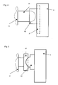
- Fig. 2 shows the schematic representation of the crash simulation system in a view of above. Identical reference numerals are used identically.
- the Vehicle 3 is about the fixedly arranged coupling element 6 and with the Coupling element connected supporting element 8 supported against the barrier 5.
- the attachment the support element on the coupling element and ultimately on the vehicle is based on the Vehicle central axis in the longitudinal direction off-center. This has at acceleration or Delay of the carriage rotation of the vehicle result. The order However, it can also be executed centrically.
- the representation is only an example selected.
- support element 8 and barrier 5 allow according to the invention a movement of the support element 8 along the Barrier relative to this.
- Accidental acceleration and movement curves of the carriage 2 arranged vehicle 3 are made possible.
- support element and coupling element are hinged together, so that the bearing surface is supported against the barrier 5, even if the vehicle is at the side of the barrier slides along or "slipping" along the barrier 5 in the vertical direction Nick movement performs.
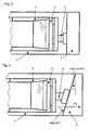
- Figure 4 shows a highly schematic representation of the support point with adjacent Barrier.
- the support element is in this embodiment in coupling rod and Shared padding. Both are hinged together.
- the connection is like that designed so that the coupling rod can pivot in any direction about the coupling pad.
- FIG. 5 shows a highly schematic view of the support point with adjacent barrier 5 in one Embodiment with lateral guidance of the coupling support 82 on the barrier 5
- Barrier 9 a groove, which can also be configured as a ball or T-guide, incorporated, in which a correspondingly worked counterpart on the coupling pad 82nd is used.
- the groove is designed so that the coupling pad in the lateral direction is movable while the coupling rod is pivotally mounted in the coupling pad.
- the Coupling rod can in turn execute pivoting movements in all directions, only the direction of movement of the coupling pad 82 on the barrier 5 is through the groove predetermined and limited.
- FIG. 6 shows a further embodiment in which the coupling element and coupling rod are integrally formed and connected via a ball joint, the coupling pad on the coupled away from the vehicle end. The coupling pad rests against the Barrier 5 off.
- Figure 7 shows a further embodiment of the carriage, in which the barrier 5 with respect to the Carriage is inclined in the vertical plane, so an enclosing angle gamma which deviates from 90 °.
- the design promotes the pitching motion of the vehicle, because due to the acceleration of the carriage with its contact point via coupling element and coupling pad is pushed against the barrier and by the slope down is relocated.
- FIG 8 shows the schematic representation of the crash simulation system in a view of above.
- Identical reference numerals to the previous figures are here given the same name used.
- the Sledges no barrier in the true sense. Rather, they are based on the Carriage 2 arranged vehicle parts 3 against a fixed to the carriage Ab benchlement off.
- the support member 11 may also be part of the carriage 2 itself be.
- the front of the vehicle is shortened in the selected representation and a Coupling element 6 limits the vehicle forward. However, it is also possible that To form coupling element of vehicle parts.
- the front of the vehicle has one angle deviating from 90 ° delta with respect to the direction of movement (symbolized by arrow P2) of the carriage 2 in the horizontal plane.
- the angles are here as preferred values.
- the angle range can fluctuate around this value to to simulate real crash situations. So z. B. accelerated lateral slipping the vehicle on the sled by flattening the front, d. H. an angle of delta> 60 ° is set.
- the non-rigid connection of coupling element 6 and support member 11 allows this invention, a movement of the Coupling element 6 along the support 11.
- Accidentally close acceleration and Movement curves of the arranged on the carriage 2 vehicle 3 are characterized allows.
- a support point of the vehicle relative to the barrier or the support element is both a point support, z.
- the support point is generally in the application as the point or area at which the vehicle is directly or over the coupling elements arranged thereon indirectly on the support element or the barrier invests.
- the support point can be in its relative position relative to the barrier or relocate the support.
Landscapes
- Physics & Mathematics (AREA)
- General Physics & Mathematics (AREA)
- Management, Administration, Business Operations System, And Electronic Commerce (AREA)
- Vibration Dampers (AREA)
- Air Bags (AREA)
- Fluid-Damping Devices (AREA)
- Control Of Position Or Direction (AREA)
- Electric Propulsion And Braking For Vehicles (AREA)
Abstract
Description
Crashtests mit realen Fahrzeugen sind sehr kostenintensiv und aufwendig, da das jeweilige Fahrzeug zumindest teilweise deformiert wird sowie darin angeordnete Sensorik und Teile des Messaufbaus nicht wieder verwendet werden können. Insbesondere in einem frühen Stadium der Fahrzeugentwicklung sind Prototypenfahrzeuge sehr teuer und stehen nicht in ausreichender Menge zur Verfügung.
Daher ist es bereits vorgeschlagen worden, Anlagen zur Crashsimulation zu nutzen. Hier werden Fahrzeuge oder Teile davon auf einem beweglichen Schlitten platziert, der jeweils stark beschleunigt oder abgebremst wird. Auf das auf dem Schlitten fest angeordnete Fahrzeug wirken dabei starke Beschleunigungs- oder Verzögerungskräfte ein. Der Antrieb des Schlittens bzw. dessen Bremseinrichtung ist so gestaltet, dass reale, bei Unfallsituationen bzw. beim Fahrzeugcrash auftretende Beschleunigungswerte erreicht bzw. nachgebildet werden können. Die beschriebene Crashsimulation ist insbesondere für die Gestaltung des Interieurs eines Fahrzeugs und die Auswirkungen auf die Insassen nützlich. Der Vorteil ist die Wiederholbarkeit mit weitgehend identischem Test-Aufbau und die Kostenersparnis, da ein modifiziertes Fahrzeug bzw. der Testaufbau weitgehend wiederverwendet werden können.
Derartige Gestaltungen bilden das reale Crashverhalten nur ungenügend ab. Bewegungen des Fahrzeugs während realer Unfallsituationen z. B. Nickbewegungen um die Fahrzeugquerachse können mit diesem Aufbau nicht realisiert werden.
Die dem Schlitten mittel- oder unmittelbar gehaltenen Fahrzeugteile stützen sich an einer fest mit dem Schlitten gekoppelten Barriere ab. Der Abstützpunkt ist dabei hinsichtlich seiner Relativlage an der Barriere nicht starr mit dieser verbunden. Erfindungsgemäß vorteilhaft wird eine Veränderung der Relativlage des Abstützpunktes zur Barriere im Verlauf des Crashtests ermöglicht.
In einer vorteilhaften Gestaltung ist das mit dem Fahrzeug fest verbundene Koppelelement gegenüber dem Auflageelement in seiner Winkellage veränderbar, so dass einer Relativbewegung des mit dem Koppelelement fest verbundenen Fahrzeuges gegenüber der Barriere ermöglicht wird, wobei das Auflageelement mit seiner der Barriere zugewandten Fläche an diesem angelegt bleibt. Das Koppelelement und das Auflageelement können in einer weiteren Ausgestaltung der Erfindung dabei aus einer Einheit bestehen. Möglich ist die Halterung in einem sogenannten Kugelgelenk, welches einen Winkelversatz des Koppelements gegenüber dem Auflageelement in horizontaler und vertikaler Ebene erlaubt. Ein Schwenken des Koppelelementes um das Auflageelement ist in jeglicher Bewegungsrichtung möglich. Das Fahrzeug kann sich demnach entsprechend dem realen Unfallverhalten gemäß der einwirkenden Beschleunigungen, seinem Schwerpunkt und der Auflageposition der Abstützung an der Barriere bewegen.
In einer weiteren Ausgestaltung ist es vorteilhaft, die Koppelauflage an der Barriere zu führen. Damit wird ein Verbleiben des Fahrzeugs auf dem Schlitten gesichert. Die Relativbewegung des Koppelelementes gegenüber der Barriere kann damit endlagenbegrenzt werden. In einer vorteilhaften Ausgestaltung kann die Koppelauflage in einer vertikalen Nut in der Barriere geführt sein und somit Nickbewegungen um die Fahrzeugquerachse ermöglichen. Zusätzlich kann durch die Anordnung eines Kugelgelenks zwischen Koppelstange und Koppelauflage eine Schwenkbewegung um die Koppelstelle zwischen Koppelstange und Koppelauflage ermöglicht werden.
Zur Sicherung des Fahrzeuges oder zur Vorgabe bestimmter Bewegungsbahnen können zusätzlich weitere Führungs- oder Sicherungselemente für das Fahrzeug vorgesehen sein.
- Figur 1
- eine schematische Darstellung der erfindungsgemäßen Crashsimulationsanlage in einer Seitenansicht,
- Figur 2 und 3
- eine schematische Darstellung der erfindungsgemäßen Crashsimulationsanlage in einer Ansicht von oben,
- Figur 4
- eine Detaildarstellung des Auflagepunktes mit angrenzender Barriere, Koppelelement und Auflageelement,
- Figur 5
- eine Detaildarstellung des Auflagepunktes mit angrenzender Barriere, Koppelelement und Auflageelement mit einer Führung der Koppelauflage,
- Figur 6
- eine Detaildarstellung des Auflagepunktes mit angrenzender Barriere, Koppelelement und Auflageelement,
- Figur 7
- eine Detaildarstellung des Auflagepunktes mit angrenzender Barriere, Koppelelement, Auflageelement und Schlitten, wobei die Barriere in vertikaler Ebene gegen den Schlitten geneigt ist,
- Figur 8
- eine schematische Darstellung der erfindungsgemäßen Crashsimulationsanlage in einer Ansicht von oben.
Das Auflageelement 8 kann dabei wenigstens in vertikale Richtung an der Barriere 5 entlang gleiten. Der dargestellte Pfeil P1 symbolisiert diese Bewegung. Die Barriere 5 ist fest an den Schlitten 2 gekoppelt und kann auch als Teil des Schlittens 2 ausgeführt sein. In einer möglichen Ausgestaltung ist sie in ihrem Winkel in horizontaler und/oder vertikaler Ebene zum Schlitten 2 einstellbar bzw. geneigt angeordnet. Der Schlitten 2 ist auf der Crashtestanlage 1 bewegbar und kann zur Spurstabilisierung auf dieser geführt sein. Die Crashtestanlage 1 ist mit einer Brems- und/oder Beschleunigungseinheit ausgestattet, die den Schlitten beschleunigen und/oder verzögern kann. Derartige Anlagen, bei denen durch Bremsen eines auf eine vordefinierte Geschwindigkeit beschleunigten Schlittens oder durch Beschleunigung des Schlittens aus einer Ruhelage durch die auftretenden
Beschleunigungen am Fahrzeug Unfallsituationen simuliert werden, sind Stand der Technik, weshalb auf deren detaillierte Beschreibung verzichtet wird. In der erfindungsgemäßen Ausgestaltung der Crashtestanlage 1 ist das Fahrzeug über Koppel- 6 und Auflageelement 8 nicht starr mit der Barriere verbunden. Vielmehr liegt in einer bevorzugten Ausführung der Erfindung das Fahrzeug lediglich an der Barriere 5 an, wobei die Beschleunigungskräfte sich an der Barriere 5 abstützen. Weil die Barriere 5 nicht starr mit dem Auflageelement 8 gekoppelt ist, kann das Auflageelement 8 an der Barriere 5 entlang gleiten und durch die BeschleunigungNerzögerung des Schlittens werden reale Bewegungskurven des Fahrzeuges nachvollzogen. Das Fahrzeug 3 sitzt im dargestellten Ausführungsbeispiel mit seinen Hinterrädern auf dem Schlitten 3 auf und stützt sich über Federn 7 an diesem ab. Die Federn 7 sind im Ausführungsbeispiel einseitig fest am Schlitten 3 angeordnet. Diese können jedoch gleichfalls einseitig fest am Fahrzeug 3 angeordnet sein oder beidseitig fahrzeug- sowie schlittenfest montiert sein. Die Federn 7 erzeugen eine Stützkraft gegen das Fahrzeuggewicht und wirken bei Beschleunigungen, positiven wie negativen (Verzögerung) des Schlittens den Nickbewegungen des Fahrzeuges entgegen. Sind die Federn 7 fahrzeug-und schlittenfest montiert, so halten sie das Fahrzeug 3 zusätzlich zur Stützbewegung gegen ein zu weites "Abheben" vom Schlitten 2. Eine Schwenkbewegung des Fahrzeuges bei Beschleunigung des Schlittens 2 um den Auflagepunkt des Auflageelements 8 ist dabei erwünscht, da diese Bewegung das realitätsnahe Crashverhalten wiederspiegelt. Der Auflagepunkt kann sich dabei lateral und vertikal verändern, wodurch Dreh- und/oder Nickbewegungen des Fahrzeuges 3 hervorgerufen werden. Ein Abheben des Fahrzeuges 3 mit seinen Hinterrädern ist dabei ebenfalls möglich. Anstelle der Hinterräder kann das Fahrzeug 3 gleichfalls auf weiteren, hier nicht dargestellten Federn stehen oder über eine ebenfalls nicht dargestellte gelenkige Führung am Schlitten beweglich gehalten sein.
- 1
- Crashsimulationsanlage
- 2
- Schlitten
- 3
- Fahrzeug
- 4
- Brems- oder Beschleunigungseinrichtung
- 5
- Barriere
- 6
- Koppelelement
- 7
- Feder
- 8
- Auflageelement
- 81
- Koppelstange
- 82
- Koppelauflage
- 9
- Führung
- 10
- Bahn
- 11
- Abstützelement
- P1
- Bewegungsrichtung Auflageelement
- P2
- Bewegungsrichtung des Schlittens
- Alpha
- Winkel zwischen Barriere und Schlitten in vertikaler Ebene
- Beta
- Winkel zwischen der Bewegungsrichtung des Schlittens (P1) und der Barriere in horizontaler Ebene
- Gamma
- Winkel zwischen Barriere und der Senkrechten zur Schlittenbewegung
- Delta
- Winkel der Front des auf dem Schlitten abgestützten Fahrzeugteils gegenüber der Bewegungsrichtung des Schlittens (P2)
Claims (27)
- Crashsimulationsanlage (1) für Kraftfahrzeuge (3) bestehend aus einem auf einer Bahn (10) beweglich angeordneten Schlitten (2), auf dem wenigstens Teile eines Fahrzeuges (3) angeordnet sind, wobei der Schlitten (2) durch wenigstens eine Antriebs- und/oder Bremseinrichtung (4) beschleunigbar und/oder verzögerbar ist,
dadurch gekennzeichnet, dass das auf dem Schlitten (2) angeordnete Fahrzeug (3) oder dessen Teile sich an einer fest mit dem Schlitten (2) gekoppelten Barriere (5) abstützen, wobei die Abstützung so gestaltet ist, dass der Abstützpunkt in seiner Relativlage zur Barriere (5) verlagerbar ist. - Crashsimulationsanlage (1) für Kraftfahrzeuge (3), bestehend aus einem auf einer Bahn (10) beweglich angeordneten Schlitten (2), auf dem wenigstens Teile eines Fahrzeuges (3) angeordnet sind, die sich mittelbar an dem Schlitten (2) abstützen, wobei der Schlitten (2) durch wenigstens eine Antriebs- und/oder Bremseinrichtung (4) beschleunigbar und/oder verzögerbar ist,
dadurch gekennzeichnet, dass das auf dem Schlitten angeordnete Fahrzeug (3) oder dessen Teile sich an einer fest mit dem Schlitten (2) gekoppelten Barriere (5) abstützen, wobei die Barriere (5) derart auf dem Schlitten angeordnet ist, dass sie in horizontaler Ebene gegenüber der Bewegungsrichtung des Schlittens einen Winkel (Beta) verschieden von 90° aufweist. - Crashsimulationsanlage für Kraftfahrzeuge nach Anspruch 1 - 2,
dadurch gekennzeichnet, dass die Abstützung des Fahrzeuges (3) oder die Abstützung von Teilen des Fahrzeuges (3) an der Barriere (5) so gestaltet ist, dass sie ein Entlanggleiten des Abstützpunktes an der Barriere (5) ermöglicht. - Crashsimulationsanlage für Kraftfahrzeuge nach Anspruch 1 - 3,
dadurch gekennzeichnet, dass die Abstützung des Fahrzeuges (3) oder die Abstützung von Teilen des Fahrzeuges (3) an der Barriere (5) hinsichtlich der Reibpaarung zwischen Abstützung und Barriere und/oder der Neigung der Barriere in horizontaler und/oder vertikaler Richtung und/oder der Abstützpunkt an der Barriere hinsichtlich seiner Position bezogen auf den Massenschwerpunkt des Fahrzeuges (3) so gestaltet ist, dass ein Entlanggleiten des Abstützpunktes an der Barriere (5) bei einer auftretenden Beschleunigung so erfolgt, dass unfallnahe Bewegungsbahnen- und Beschleunigungskurven im Fahrzeug (3) auftreten. - Crashsimulationsanlage für Kraftfahrzeuge nach einem der vorherigen Ansprüche,
dadurch gekennzeichnet, dass in horizontaler Ebene der Winkel (Beta), den die mit dem Schlitten (2) verbundene Barriere (5) gegenüber der Bewegungsrichtung des Schlittens (2) aufweist, vorzugsweise 60° ist. - Crashsimulationsanlage für Kraftfahrzeuge nach einem der vorherigen Ansprüche,
dadurch gekennzeichnet, dass die mit dem Schlitten (2) verbundene Barriere (5) in horizontaler Ebene in ihrem Winkel (Beta) gegenüber der Bewegungsrichtung des Schlittens einstellbar ist. - Crashsimulationsanlage für Kraftfahrzeuge nach einem der vorherigen Ansprüche,
dadurch gekennzeichnet, dass die mit dem Schlitten (2) verbundene Barriere (5) in vertikaler Ebene in ihrem Winkel (Gamma) gegenüber der Bewegungsrichtung des Schlittens (2) einen von 90° abweichenden Winkel (Gamma) aufweist. - Crashsimulationsanlage für Kraftfahrzeuge nach einem der vorherigen Ansprüche,
dadurch gekennzeichnet, dass die mit dem Schlitten (2) verbundene Barriere (5) in vertikaler Ebene in ihrem Winkel (Gamma) gegenüber der Bewegungsrichtung des Schlittens (2) einstellbar ist. - Crashsimulationsanlage für Kraftfahrzeuge nach einem der vorherigen Ansprüche,
dadurch gekennzeichnet, dass ein mit dem Fahrzeug (3) fest verbundenes Koppelelement (6) sich über ein Auflageelement (8) an der Barriere (5) abstützt, welches in wenigstens eine Richtung entlang der Barriere (5) bewegbar ist. - Crashsimulationsanlage für Kraftfahrzeuge nach Anspruch 7,
dadurch gekennzeichnet, dass das mit dem Fahrzeug (3) fest verbundene Koppelelement (6) gegenüber dem Auflageelement (8) in seiner Winkellage veränderbar ist. - Crashsimulationsanlage für Kraftfahrzeuge nach einem der vorherigen Ansprüche,
dadurch gekennzeichnet, dass das mit dem Fahrzeug fest verbundene Koppelelement (6) und das Auflageelement (8) aus einer Einheit bestehen. - Crashsimulationsanlage für Kraftfahrzeuge nach einem der vorherigen Ansprüche,
dadurch gekennzeichnet, dass das Auflageelement (8) aus einer Koppelstange (81) und einer Koppelauflage (82) besteht, die vorzugsweise durch ein Kugelgelenk verbunden sind. - Crashsimulationsanlage für Kraftfahrzeuge nach einem der vorherigen Ansprüche,
dadurch gekennzeichnet, dass die Koppelauflage (82) an der Barriere (5) bewegbar geführt ist. - Crashsimulationsanlage für Kraftfahrzeuge nach einem der vorherigen Ansprüche,
dadurch gekennzeichnet, dass die Oberflächenpaarung von Koppelauflage (82) und Barriere (5) und/oder die Oberflächenpaarung von Koppelstange (81) und Koppelauflage (82) so gestaltet ist, dass sie der Relativbewegung von Koppelauflage (82) und Barriere (5) und/oder der Relativbewegung von Koppelstange (81) und Koppelauflage (82) einen Widerstand entgegensetzt. - Crashsimulationsanlage für Kraftfahrzeuge nach einem der vorherigen Ansprüche,
dadurch gekennzeichnet, dass das auf dem Schlitten (2) angeordnete Fahrzeug (3) oder dessen Teile in vertikaler Richtung nachgiebig gegen den Schlitten (2) abgestützt ist. - Crashsimulationsanlage für Kraftfahrzeuge nach Anspruch 13,
dadurch gekennzeichnet, dass das vertikal elastisch auf dem Schlitten (2) abgestützte Fahrzeug (3) oder dessen Teile von wenigstens einer Feder (7) in vertikaler Richtung gehalten werden. - Crashsimulationsanlage für Kraftfahrzeuge nach einem der vorherigen Ansprüche,
dadurch gekennzeichnet, dass zusätzlich zur Abstützung durch die Federn (7) eine Führung des Fahrzeuges (3) auf dem Schlitten vorgesehen ist. - Crashsimulationsanlage (1) für Kraftfahrzeuge (3) bestehend aus einem auf einer Bahn (10) beweglich angeordneten Schlitten (2), auf dem wenigstens Teile eines Fahrzeuges (3) angeordnet sind, die sich mittelbar an dem Schlitten (2) abstützen, wobei der Schlitten (2) durch wenigstens eine Antriebs- und/oder Bremseinrichtung (4) beschleunigbar und/oder verzögerbar ist,
dadurch gekennzeichnet, dass das auf dem Schlitten (2) abgestützte Fahrzeug (3) oder dessen Teile sich an einem fest mit dem Schlitten (2) gekoppelten Abstützelement (11) abstützen, wobei die Abstützung so gestaltet ist, dass sich die Front des abgestützten Fahrzeuges oder die Front von dessen Teilen direkt oder indirekt über ein Koppelelement (6) am Abstützelement (11) anlieget, wobei der Abstützpunkt in seiner Relativlage zum Abstützelement (11) verlagerbar ist. - Crashsimulationsanlage für Kraftfahrzeuge nach Anspruch 18,
dadurch gekennzeichnet, dass die Abstützung der Front des Fahrzeuges (3) oder die Front des Koppelelements (6) gegenüber dem Abstützelement (11) so gestaltet ist, dass die Front des abgestützte Fahrzeug oder des Koppeleiements (6) in ihrer Relativlage zum Abstützelement (11) verlagerbar ist. - Crashsimulationsanlage für Kraftfahrzeuge nach einem der Ansprüche 18 bis 19,
dadurch gekennzeichnet, dass die Front des auf dem Schlitten (2) abgestützten Fahrzeugs (3) oder die Front von dessen Teilen mittel- oder unmittelbar über das Koppelelement (6) am Abstützelement (11) anliegt. - Crashsimulationsanlage für Kraftfahrzeuge nach einem der Ansprüche 18-20,
dadurch gekennzeichnet, dass die Front des auf dem Schlitten (2) mittel- oder unmittelbar abgestützten Fahrzeugs (3) oder die Front von dessen Teilem am Abstützelement (11) anliegt und in horizontaler Ebene einen gegenüber der Bewegungsrichtung des Schlittens (2) gemessenen Winkel (Delta) aufweist, der von 90° abweicht. - Crashsimulationsanlage für Kraftfahrzeuge nach einem der Ansprüche 18-21,
dadurch gekennzeichnet, dass der Winkel (Delta) der Front des auf dem Schlitten (2) mittel- oder unmittelbar abgestützten Fahrzeugs (3) oder dessen Teile gegenüber der Bewegungsrichtung des Schlittens (2) vorzugsweise 60° beträgt. - Crashsimulationsanlage für Kraftfahrzeuge nach Anspruch 18-22,
dadurch gekennzeichnet, dass die Front des auf dem Schlitten (2) mittel- oder unmittelbar abgestützten Fahrzeugs (3) oder die Front von dessen Teilen, die am Abstützelement (11) anliegt in vertikaler Ebene einen gegenüber der Bewegungsrichtung des Schlittens (2) gemessenen Winkel aufweist, der von 90° abweicht. - Crashsimulationsanlage für Kraftfahrzeuge nach einem der Ansprüche 18-23,
dadurch gekennzeichnet, dass das auf dem Schlitten (2) angeordnete Fahrzeug (3) oder dessen Teile in vertikaler Richtung nachgiebig gegen den Schlitten (2) abgestützt sind. - Crashsimulationsanlage für Kraftfahrzeuge nach Anspruch 24,
dadurch gekennzeichnet, dass das vertikal elastisch auf dem Schlitten (2) abgestützte Fahrzeug (3) oder dessen Teile von wenigstens einer Feder (7) in vertikaler Richtung gehalten werden. - Crashsimulationsanlage für Kraftfahrzeuge nach einem der Ansprüche 18 -25,
dadurch gekennzeichnet, dass zusätzlich zur Abstützung durch die Federn (7) eine Führung des Fahrzeuges (3) auf dem Schlitten vorgesehen ist. - Crashsimulationsanlage für Kraftfahrzeuge nach einem der vorherigen Ansprüche,
dadurch gekennzeichnet, dass der Abstützpunkt des Fahrzeuges (3) an der Barriere (5) oder am Abstützelement (11) in horizontaler und/oder vertikaler Position einstellbar ist.
Applications Claiming Priority (2)
| Application Number | Priority Date | Filing Date | Title |
|---|---|---|---|
| DE102004027221 | 2004-05-28 | ||
| DE102004027221A DE102004027221A1 (de) | 2004-05-28 | 2004-05-28 | Crashsimulationsanlage für Kraftfahrzeuge |
Publications (2)
| Publication Number | Publication Date |
|---|---|
| EP1600756A1 true EP1600756A1 (de) | 2005-11-30 |
| EP1600756B1 EP1600756B1 (de) | 2006-12-06 |
Family
ID=34934389
Family Applications (1)
| Application Number | Title | Priority Date | Filing Date |
|---|---|---|---|
| EP05006082A Expired - Lifetime EP1600756B1 (de) | 2004-05-28 | 2005-03-19 | Crashsimulationsanlage für Kraftfahrfzeuge |
Country Status (3)
| Country | Link |
|---|---|
| EP (1) | EP1600756B1 (de) |
| AT (1) | ATE347690T1 (de) |
| DE (2) | DE102004027221A1 (de) |
Cited By (7)
| Publication number | Priority date | Publication date | Assignee | Title |
|---|---|---|---|---|
| EP1657538B1 (de) * | 2004-10-20 | 2007-08-08 | IAV GmbH Ingenieurgesellschaft Auto und Verkehr | Crashsimulationsanlage für Fahrzeuge |
| DE102008010232A1 (de) * | 2008-02-21 | 2009-09-10 | Continental Safety Engineering International Gmbh | Testvorrichtung und Verfahren für ein passives Sicherheitssystem eines Kraftfahrzeugs |
| CN103454059A (zh) * | 2013-04-10 | 2013-12-18 | 浙江吉利汽车研究院有限公司杭州分公司 | 汽车碰撞试验定位装置及定位方法 |
| CN108507798A (zh) * | 2017-12-27 | 2018-09-07 | 南昌大学 | 工字梁上小车加速装置 |
| CN114722600A (zh) * | 2022-03-31 | 2022-07-08 | 东风汽车集团股份有限公司 | 一种确定主仪表板最恶劣碰撞方向的方法及存储介质 |
| CN115824673A (zh) * | 2023-02-16 | 2023-03-21 | 浙江嘉傲科技有限公司 | 汽车头部碰撞检测装置及方法 |
| CN117538072A (zh) * | 2023-11-21 | 2024-02-09 | 中汽研汽车检验中心(武汉)有限公司 | 一种弹簧式行人保护腿型试验发射装置和试验方法 |
Families Citing this family (3)
| Publication number | Priority date | Publication date | Assignee | Title |
|---|---|---|---|---|
| DE102007042775A1 (de) * | 2007-09-07 | 2009-03-12 | Dsd Dr. Steffan Datentechnik Gmbh | Verfahren und Vorrichtung zur Durchführung von Crash-Schlitten-Versuchen |
| DE102007056573B4 (de) * | 2007-11-23 | 2017-09-28 | Audi Ag | Verfahren zur Durchführung von Crash-Schlitten-Versuchen mit vor dem Aufprall auftretender Gierbewegung |
| CN118464474B (zh) * | 2024-07-09 | 2024-09-13 | 山东传奇贝贝儿童用品有限公司 | 一种婴儿车撞击性能测试设备 |
Citations (3)
| Publication number | Priority date | Publication date | Assignee | Title |
|---|---|---|---|---|
| US5872321A (en) * | 1997-12-08 | 1999-02-16 | The United States Of America As Represented By The Secretary Of The Navy | Side impact injury test apparatus |
| DE19805512A1 (de) * | 1998-02-11 | 1999-08-12 | Bayerische Motoren Werke Ag | Kraftfahrzeug-Kollisionssimulator |
| DE19857429A1 (de) * | 1998-12-12 | 2000-06-15 | Instron Schenck Testing System | Prüfeinrichtung zur Kraftfahrzeug-Crashsimulation |
-
2004
- 2004-05-28 DE DE102004027221A patent/DE102004027221A1/de not_active Withdrawn
-
2005
- 2005-03-19 EP EP05006082A patent/EP1600756B1/de not_active Expired - Lifetime
- 2005-03-19 DE DE502005000216T patent/DE502005000216D1/de not_active Expired - Lifetime
- 2005-03-19 AT AT05006082T patent/ATE347690T1/de not_active IP Right Cessation
Patent Citations (3)
| Publication number | Priority date | Publication date | Assignee | Title |
|---|---|---|---|---|
| US5872321A (en) * | 1997-12-08 | 1999-02-16 | The United States Of America As Represented By The Secretary Of The Navy | Side impact injury test apparatus |
| DE19805512A1 (de) * | 1998-02-11 | 1999-08-12 | Bayerische Motoren Werke Ag | Kraftfahrzeug-Kollisionssimulator |
| DE19857429A1 (de) * | 1998-12-12 | 2000-06-15 | Instron Schenck Testing System | Prüfeinrichtung zur Kraftfahrzeug-Crashsimulation |
Cited By (12)
| Publication number | Priority date | Publication date | Assignee | Title |
|---|---|---|---|---|
| EP1657538B1 (de) * | 2004-10-20 | 2007-08-08 | IAV GmbH Ingenieurgesellschaft Auto und Verkehr | Crashsimulationsanlage für Fahrzeuge |
| DE102008010232A1 (de) * | 2008-02-21 | 2009-09-10 | Continental Safety Engineering International Gmbh | Testvorrichtung und Verfahren für ein passives Sicherheitssystem eines Kraftfahrzeugs |
| DE102008010232B4 (de) * | 2008-02-21 | 2009-11-26 | Continental Safety Engineering International Gmbh | Testvorrichtung und Verfahren für ein passives Sicherheitssystem eines Kraftfahrzeugs |
| CN103454059A (zh) * | 2013-04-10 | 2013-12-18 | 浙江吉利汽车研究院有限公司杭州分公司 | 汽车碰撞试验定位装置及定位方法 |
| CN103454059B (zh) * | 2013-04-10 | 2015-12-09 | 浙江吉利汽车研究院有限公司杭州分公司 | 汽车碰撞试验定位装置及定位方法 |
| CN108507798A (zh) * | 2017-12-27 | 2018-09-07 | 南昌大学 | 工字梁上小车加速装置 |
| CN108507798B (zh) * | 2017-12-27 | 2023-12-22 | 南昌航空大学 | 工字梁上小车加速装置 |
| CN114722600A (zh) * | 2022-03-31 | 2022-07-08 | 东风汽车集团股份有限公司 | 一种确定主仪表板最恶劣碰撞方向的方法及存储介质 |
| CN115824673A (zh) * | 2023-02-16 | 2023-03-21 | 浙江嘉傲科技有限公司 | 汽车头部碰撞检测装置及方法 |
| CN115824673B (zh) * | 2023-02-16 | 2023-06-02 | 浙江嘉傲科技有限公司 | 汽车头部碰撞检测装置及方法 |
| CN117538072A (zh) * | 2023-11-21 | 2024-02-09 | 中汽研汽车检验中心(武汉)有限公司 | 一种弹簧式行人保护腿型试验发射装置和试验方法 |
| CN117538072B (zh) * | 2023-11-21 | 2024-05-28 | 中汽研汽车检验中心(武汉)有限公司 | 一种弹簧式行人保护腿型试验方法 |
Also Published As
| Publication number | Publication date |
|---|---|
| ATE347690T1 (de) | 2006-12-15 |
| DE502005000216D1 (de) | 2007-01-18 |
| EP1600756B1 (de) | 2006-12-06 |
| DE102004027221A1 (de) | 2005-12-15 |
Similar Documents
| Publication | Publication Date | Title |
|---|---|---|
| DE112009000488B4 (de) | Testsystem mit Strebenanordnung sowie Verfahren | |
| DE10341328B4 (de) | Vorrichtung und zugehöriges Verfahren zum Insassenschutz in einem Fahrzeug | |
| EP2415632B1 (de) | Horizontalfederung mit Neigungsausgleich | |
| DE102011011018B3 (de) | Pendelfallanlage | |
| EP2069741B1 (de) | Vorrichtung und verfahren zur bestimmung der trägheitsparameter eines körpers | |
| EP0952033B1 (de) | Fahrzeugsitz mit einer Kopfstütze | |
| EP2098850B1 (de) | Anordnung zur Simulation von Aufprallunfällen | |
| DE112009000493T5 (de) | Haltesystem | |
| DE4204147C2 (de) | Vorrichtung mit Gelenkarmen für einen Helm | |
| EP1600756B1 (de) | Crashsimulationsanlage für Kraftfahrfzeuge | |
| DE2330093A1 (de) | Versuchspuppe fuer simulierte auffahrunfaelle von kraftfahrzeugen | |
| DE102020130510B3 (de) | Fahrzeugsimulator | |
| DE102007042775A1 (de) | Verfahren und Vorrichtung zur Durchführung von Crash-Schlitten-Versuchen | |
| DE1187937B (de) | Stossdaempfungs- und Stabilisierungs-Vorrichtung fuer Fahrzeuge, insbesondere Kraftfahrzeuge | |
| EP1657538B1 (de) | Crashsimulationsanlage für Fahrzeuge | |
| DE19750157A1 (de) | Prüfeinrichtung zur Crashprüfung von Teilsystemen eines Kraftfahrzeugs bei simulierter Seitenkollision | |
| DE10252204B3 (de) | Fahrzeugsitzvorrichtung | |
| EP0252232A2 (de) | Haltevorrichtung für eine Lenksäule eines Kraftfahrzeugs | |
| DE102019116663A1 (de) | Neigungsmechanik für einspurige Dummy Fahrzeuge | |
| DE102007021666B4 (de) | Vorrichtung zur Erprobung von Maßnahmen für den Kollisionsschutz bei Kraftfahrzeugen | |
| DE2510100A1 (de) | Elastische daempfung einer stossstange | |
| DE102015211092A1 (de) | Armauflagevorrichtung für einen Fahrzeuginnenraum | |
| EP3987266A1 (de) | Verfahrbare plattform für ein dummy-element | |
| DE102004029426A1 (de) | Vorrichtung und Verfahren zur Simulierung einer Kollision, insbesondere eines Kraftfahrzeugs mit einem Gegenstand | |
| WO2010000609A1 (de) | Schlitten |
Legal Events
| Date | Code | Title | Description |
|---|---|---|---|
| PUAI | Public reference made under article 153(3) epc to a published international application that has entered the european phase |
Free format text: ORIGINAL CODE: 0009012 |
|
| AK | Designated contracting states |
Kind code of ref document: A1 Designated state(s): AT BE BG CH CY CZ DE DK EE ES FI FR GB GR HU IE IS IT LI LT LU MC NL PL PT RO SE SI SK TR |
|
| AX | Request for extension of the european patent |
Extension state: AL BA HR LV MK YU |
|
| 17P | Request for examination filed |
Effective date: 20051216 |
|
| GRAP | Despatch of communication of intention to grant a patent |
Free format text: ORIGINAL CODE: EPIDOSNIGR1 |
|
| AKX | Designation fees paid |
Designated state(s): AT BE BG CH CY CZ DE DK EE ES FI FR GB GR HU IE IS IT LI LT LU MC NL PL PT RO SE SI SK TR |
|
| GRAS | Grant fee paid |
Free format text: ORIGINAL CODE: EPIDOSNIGR3 |
|
| GRAA | (expected) grant |
Free format text: ORIGINAL CODE: 0009210 |
|
| AK | Designated contracting states |
Kind code of ref document: B1 Designated state(s): AT BE BG CH CY CZ DE DK EE ES FI FR GB GR HU IE IS IT LI LT LU MC NL PL PT RO SE SI SK TR |
|
| PG25 | Lapsed in a contracting state [announced via postgrant information from national office to epo] |
Ref country code: LT Free format text: LAPSE BECAUSE OF FAILURE TO SUBMIT A TRANSLATION OF THE DESCRIPTION OR TO PAY THE FEE WITHIN THE PRESCRIBED TIME-LIMIT Effective date: 20061206 Ref country code: FI Free format text: LAPSE BECAUSE OF FAILURE TO SUBMIT A TRANSLATION OF THE DESCRIPTION OR TO PAY THE FEE WITHIN THE PRESCRIBED TIME-LIMIT Effective date: 20061206 Ref country code: PL Free format text: LAPSE BECAUSE OF FAILURE TO SUBMIT A TRANSLATION OF THE DESCRIPTION OR TO PAY THE FEE WITHIN THE PRESCRIBED TIME-LIMIT Effective date: 20061206 Ref country code: NL Free format text: LAPSE BECAUSE OF FAILURE TO SUBMIT A TRANSLATION OF THE DESCRIPTION OR TO PAY THE FEE WITHIN THE PRESCRIBED TIME-LIMIT Effective date: 20061206 Ref country code: RO Free format text: LAPSE BECAUSE OF FAILURE TO SUBMIT A TRANSLATION OF THE DESCRIPTION OR TO PAY THE FEE WITHIN THE PRESCRIBED TIME-LIMIT Effective date: 20061206 Ref country code: SI Free format text: LAPSE BECAUSE OF FAILURE TO SUBMIT A TRANSLATION OF THE DESCRIPTION OR TO PAY THE FEE WITHIN THE PRESCRIBED TIME-LIMIT Effective date: 20061206 Ref country code: IE Free format text: LAPSE BECAUSE OF FAILURE TO SUBMIT A TRANSLATION OF THE DESCRIPTION OR TO PAY THE FEE WITHIN THE PRESCRIBED TIME-LIMIT Effective date: 20061206 Ref country code: SK Free format text: LAPSE BECAUSE OF FAILURE TO SUBMIT A TRANSLATION OF THE DESCRIPTION OR TO PAY THE FEE WITHIN THE PRESCRIBED TIME-LIMIT Effective date: 20061206 Ref country code: DK Free format text: LAPSE BECAUSE OF FAILURE TO SUBMIT A TRANSLATION OF THE DESCRIPTION OR TO PAY THE FEE WITHIN THE PRESCRIBED TIME-LIMIT Effective date: 20061206 Ref country code: CZ Free format text: LAPSE BECAUSE OF FAILURE TO SUBMIT A TRANSLATION OF THE DESCRIPTION OR TO PAY THE FEE WITHIN THE PRESCRIBED TIME-LIMIT Effective date: 20061206 Ref country code: IT Free format text: LAPSE BECAUSE OF FAILURE TO SUBMIT A TRANSLATION OF THE DESCRIPTION OR TO PAY THE FEE WITHIN THE PRESCRIBED TIME-LIMIT;WARNING: LAPSES OF ITALIAN PATENTS WITH EFFECTIVE DATE BEFORE 2007 MAY HAVE OCCURRED AT ANY TIME BEFORE 2007. THE CORRECT EFFECTIVE DATE MAY BE DIFFERENT FROM THE ONE RECORDED. Effective date: 20061206 |
|
| REG | Reference to a national code |
Ref country code: GB Ref legal event code: FG4D Free format text: NOT ENGLISH |
|
| REG | Reference to a national code |
Ref country code: CH Ref legal event code: EP |
|
| REG | Reference to a national code |
Ref country code: IE Ref legal event code: FG4D Free format text: LANGUAGE OF EP DOCUMENT: GERMAN |
|
| REF | Corresponds to: |
Ref document number: 502005000216 Country of ref document: DE Date of ref document: 20070118 Kind code of ref document: P |
|
| PG25 | Lapsed in a contracting state [announced via postgrant information from national office to epo] |
Ref country code: BG Free format text: LAPSE BECAUSE OF FAILURE TO SUBMIT A TRANSLATION OF THE DESCRIPTION OR TO PAY THE FEE WITHIN THE PRESCRIBED TIME-LIMIT Effective date: 20070306 |
|
| REG | Reference to a national code |
Ref country code: SE Ref legal event code: TRGR |
|
| GBT | Gb: translation of ep patent filed (gb section 77(6)(a)/1977) |
Effective date: 20070208 |
|
| PG25 | Lapsed in a contracting state [announced via postgrant information from national office to epo] |
Ref country code: ES Free format text: LAPSE BECAUSE OF FAILURE TO SUBMIT A TRANSLATION OF THE DESCRIPTION OR TO PAY THE FEE WITHIN THE PRESCRIBED TIME-LIMIT Effective date: 20070317 |
|
| PG25 | Lapsed in a contracting state [announced via postgrant information from national office to epo] |
Ref country code: IS Free format text: LAPSE BECAUSE OF FAILURE TO SUBMIT A TRANSLATION OF THE DESCRIPTION OR TO PAY THE FEE WITHIN THE PRESCRIBED TIME-LIMIT Effective date: 20070406 |
|
| RIN2 | Information on inventor provided after grant (corrected) |
Inventor name: TOUSEN, MAMDOUH, DR. Inventor name: WEIKARD, FRITZ Inventor name: QUEDENBAUM, LUTZ |
|
| PG25 | Lapsed in a contracting state [announced via postgrant information from national office to epo] |
Ref country code: PT Free format text: LAPSE BECAUSE OF FAILURE TO SUBMIT A TRANSLATION OF THE DESCRIPTION OR TO PAY THE FEE WITHIN THE PRESCRIBED TIME-LIMIT Effective date: 20070507 |
|
| NLV1 | Nl: lapsed or annulled due to failure to fulfill the requirements of art. 29p and 29m of the patents act | ||
| ET | Fr: translation filed | ||
| PLBE | No opposition filed within time limit |
Free format text: ORIGINAL CODE: 0009261 |
|
| STAA | Information on the status of an ep patent application or granted ep patent |
Free format text: STATUS: NO OPPOSITION FILED WITHIN TIME LIMIT |
|
| 26N | No opposition filed |
Effective date: 20070907 |
|
| BERE | Be: lapsed |
Owner name: IAV G.M.B.H. INGENIEURGESELLSCHAFT AUTO UND VERKEH Effective date: 20070331 |
|
| PG25 | Lapsed in a contracting state [announced via postgrant information from national office to epo] |
Ref country code: BE Free format text: LAPSE BECAUSE OF NON-PAYMENT OF DUE FEES Effective date: 20070331 |
|
| PG25 | Lapsed in a contracting state [announced via postgrant information from national office to epo] |
Ref country code: MC Free format text: LAPSE BECAUSE OF NON-PAYMENT OF DUE FEES Effective date: 20070331 |
|
| PG25 | Lapsed in a contracting state [announced via postgrant information from national office to epo] |
Ref country code: GR Free format text: LAPSE BECAUSE OF FAILURE TO SUBMIT A TRANSLATION OF THE DESCRIPTION OR TO PAY THE FEE WITHIN THE PRESCRIBED TIME-LIMIT Effective date: 20070307 |
|
| PG25 | Lapsed in a contracting state [announced via postgrant information from national office to epo] |
Ref country code: EE Free format text: LAPSE BECAUSE OF FAILURE TO SUBMIT A TRANSLATION OF THE DESCRIPTION OR TO PAY THE FEE WITHIN THE PRESCRIBED TIME-LIMIT Effective date: 20061206 |
|
| PGFP | Annual fee paid to national office [announced via postgrant information from national office to epo] |
Ref country code: AT Payment date: 20090309 Year of fee payment: 5 Ref country code: FR Payment date: 20081121 Year of fee payment: 5 |
|
| PGFP | Annual fee paid to national office [announced via postgrant information from national office to epo] |
Ref country code: GB Payment date: 20090310 Year of fee payment: 5 |
|
| PG25 | Lapsed in a contracting state [announced via postgrant information from national office to epo] |
Ref country code: LU Free format text: LAPSE BECAUSE OF NON-PAYMENT OF DUE FEES Effective date: 20070319 Ref country code: CY Free format text: LAPSE BECAUSE OF FAILURE TO SUBMIT A TRANSLATION OF THE DESCRIPTION OR TO PAY THE FEE WITHIN THE PRESCRIBED TIME-LIMIT Effective date: 20061206 |
|
| PGFP | Annual fee paid to national office [announced via postgrant information from national office to epo] |
Ref country code: SE Payment date: 20090318 Year of fee payment: 5 |
|
| PG25 | Lapsed in a contracting state [announced via postgrant information from national office to epo] |
Ref country code: TR Free format text: LAPSE BECAUSE OF FAILURE TO SUBMIT A TRANSLATION OF THE DESCRIPTION OR TO PAY THE FEE WITHIN THE PRESCRIBED TIME-LIMIT Effective date: 20061206 Ref country code: HU Free format text: LAPSE BECAUSE OF FAILURE TO SUBMIT A TRANSLATION OF THE DESCRIPTION OR TO PAY THE FEE WITHIN THE PRESCRIBED TIME-LIMIT Effective date: 20070607 |
|
| REG | Reference to a national code |
Ref country code: CH Ref legal event code: PL |
|
| PG25 | Lapsed in a contracting state [announced via postgrant information from national office to epo] |
Ref country code: LI Free format text: LAPSE BECAUSE OF NON-PAYMENT OF DUE FEES Effective date: 20090331 Ref country code: CH Free format text: LAPSE BECAUSE OF NON-PAYMENT OF DUE FEES Effective date: 20090331 |
|
| EUG | Se: european patent has lapsed | ||
| GBPC | Gb: european patent ceased through non-payment of renewal fee |
Effective date: 20100319 |
|
| PG25 | Lapsed in a contracting state [announced via postgrant information from national office to epo] |
Ref country code: AT Free format text: LAPSE BECAUSE OF NON-PAYMENT OF DUE FEES Effective date: 20100319 |
|
| REG | Reference to a national code |
Ref country code: FR Ref legal event code: ST Effective date: 20101130 |
|
| PG25 | Lapsed in a contracting state [announced via postgrant information from national office to epo] |
Ref country code: FR Free format text: LAPSE BECAUSE OF NON-PAYMENT OF DUE FEES Effective date: 20100331 |
|
| PG25 | Lapsed in a contracting state [announced via postgrant information from national office to epo] |
Ref country code: GB Free format text: LAPSE BECAUSE OF NON-PAYMENT OF DUE FEES Effective date: 20100319 |
|
| PGFP | Annual fee paid to national office [announced via postgrant information from national office to epo] |
Ref country code: DE Payment date: 20120425 Year of fee payment: 8 |
|
| PG25 | Lapsed in a contracting state [announced via postgrant information from national office to epo] |
Ref country code: SE Free format text: LAPSE BECAUSE OF NON-PAYMENT OF DUE FEES Effective date: 20100320 |
|
| REG | Reference to a national code |
Ref country code: DE Ref legal event code: R119 Ref document number: 502005000216 Country of ref document: DE Effective date: 20131001 |
|
| PG25 | Lapsed in a contracting state [announced via postgrant information from national office to epo] |
Ref country code: DE Free format text: LAPSE BECAUSE OF NON-PAYMENT OF DUE FEES Effective date: 20131001 |