EP1600627B1 - Steuerventil - Google Patents
Steuerventil Download PDFInfo
- Publication number
- EP1600627B1 EP1600627B1 EP05010378A EP05010378A EP1600627B1 EP 1600627 B1 EP1600627 B1 EP 1600627B1 EP 05010378 A EP05010378 A EP 05010378A EP 05010378 A EP05010378 A EP 05010378A EP 1600627 B1 EP1600627 B1 EP 1600627B1
- Authority
- EP
- European Patent Office
- Prior art keywords
- diameter
- control valve
- valve according
- sealing
- chamfers
- Prior art date
- Legal status (The legal status is an assumption and is not a legal conclusion. Google has not performed a legal analysis and makes no representation as to the accuracy of the status listed.)
- Expired - Lifetime
Links
- 238000007789 sealing Methods 0.000 claims description 58
- 239000000463 material Substances 0.000 description 7
- 239000000446 fuel Substances 0.000 description 6
- 238000006073 displacement reaction Methods 0.000 description 4
- 230000002349 favourable effect Effects 0.000 description 3
- 238000009825 accumulation Methods 0.000 description 2
- 230000007423 decrease Effects 0.000 description 2
- 230000000694 effects Effects 0.000 description 2
- 238000002485 combustion reaction Methods 0.000 description 1
- 238000005553 drilling Methods 0.000 description 1
- 230000003628 erosive effect Effects 0.000 description 1
- 238000002347 injection Methods 0.000 description 1
- 239000007924 injection Substances 0.000 description 1
- 230000002265 prevention Effects 0.000 description 1
- 230000002035 prolonged effect Effects 0.000 description 1
Images


Classifications
-
- F—MECHANICAL ENGINEERING; LIGHTING; HEATING; WEAPONS; BLASTING
- F02—COMBUSTION ENGINES; HOT-GAS OR COMBUSTION-PRODUCT ENGINE PLANTS
- F02M—SUPPLYING COMBUSTION ENGINES IN GENERAL WITH COMBUSTIBLE MIXTURES OR CONSTITUENTS THEREOF
- F02M63/00—Other fuel-injection apparatus having pertinent characteristics not provided for in groups F02M39/00 - F02M57/00 or F02M67/00; Details, component parts, or accessories of fuel-injection apparatus, not provided for in, or of interest apart from, the apparatus of groups F02M39/00 - F02M61/00 or F02M67/00; Combination of fuel pump with other devices, e.g. lubricating oil pump
- F02M63/0012—Valves
- F02M63/0031—Valves characterized by the type of valves, e.g. special valve member details, valve seat details, valve housing details
-
- F—MECHANICAL ENGINEERING; LIGHTING; HEATING; WEAPONS; BLASTING
- F02—COMBUSTION ENGINES; HOT-GAS OR COMBUSTION-PRODUCT ENGINE PLANTS
- F02M—SUPPLYING COMBUSTION ENGINES IN GENERAL WITH COMBUSTIBLE MIXTURES OR CONSTITUENTS THEREOF
- F02M47/00—Fuel-injection apparatus operated cyclically with fuel-injection valves actuated by fluid pressure
- F02M47/02—Fuel-injection apparatus operated cyclically with fuel-injection valves actuated by fluid pressure of accumulator-injector type, i.e. having fuel pressure of accumulator tending to open, and fuel pressure in other chamber tending to close, injection valves and having means for periodically releasing that closing pressure
- F02M47/027—Electrically actuated valves draining the chamber to release the closing pressure
-
- F—MECHANICAL ENGINEERING; LIGHTING; HEATING; WEAPONS; BLASTING
- F02—COMBUSTION ENGINES; HOT-GAS OR COMBUSTION-PRODUCT ENGINE PLANTS
- F02M—SUPPLYING COMBUSTION ENGINES IN GENERAL WITH COMBUSTIBLE MIXTURES OR CONSTITUENTS THEREOF
- F02M63/00—Other fuel-injection apparatus having pertinent characteristics not provided for in groups F02M39/00 - F02M57/00 or F02M67/00; Details, component parts, or accessories of fuel-injection apparatus, not provided for in, or of interest apart from, the apparatus of groups F02M39/00 - F02M61/00 or F02M67/00; Combination of fuel pump with other devices, e.g. lubricating oil pump
- F02M63/0012—Valves
- F02M63/0014—Valves characterised by the valve actuating means
- F02M63/0015—Valves characterised by the valve actuating means electrical, e.g. using solenoid
-
- F—MECHANICAL ENGINEERING; LIGHTING; HEATING; WEAPONS; BLASTING
- F02—COMBUSTION ENGINES; HOT-GAS OR COMBUSTION-PRODUCT ENGINE PLANTS
- F02M—SUPPLYING COMBUSTION ENGINES IN GENERAL WITH COMBUSTIBLE MIXTURES OR CONSTITUENTS THEREOF
- F02M2200/00—Details of fuel-injection apparatus, not otherwise provided for
- F02M2200/02—Fuel-injection apparatus having means for reducing wear
-
- F—MECHANICAL ENGINEERING; LIGHTING; HEATING; WEAPONS; BLASTING
- F02—COMBUSTION ENGINES; HOT-GAS OR COMBUSTION-PRODUCT ENGINE PLANTS
- F02M—SUPPLYING COMBUSTION ENGINES IN GENERAL WITH COMBUSTIBLE MIXTURES OR CONSTITUENTS THEREOF
- F02M2200/00—Details of fuel-injection apparatus, not otherwise provided for
- F02M2200/04—Fuel-injection apparatus having means for avoiding effect of cavitation, e.g. erosion
-
- F—MECHANICAL ENGINEERING; LIGHTING; HEATING; WEAPONS; BLASTING
- F02—COMBUSTION ENGINES; HOT-GAS OR COMBUSTION-PRODUCT ENGINE PLANTS
- F02M—SUPPLYING COMBUSTION ENGINES IN GENERAL WITH COMBUSTIBLE MIXTURES OR CONSTITUENTS THEREOF
- F02M2200/00—Details of fuel-injection apparatus, not otherwise provided for
- F02M2200/16—Sealing of fuel injection apparatus not otherwise provided for
Definitions
- control valve for controlling injection injectors for internal combustion engines, which controls the adjusting movements of the valve closing member.
- a control valve has a hubbeweglichen, control piston, which may be, for example, solenoid or piezobetätigt.
- the control piston is located with a front side in the region of a closing head in a pressure chamber, on which a throttled, emanating from a control chamber of the valve closure member high pressure side inlet opens, and from which a throttled and controlled by the control piston expires.
- the control chamber of the valve closure member is in throttled communication with a high pressure line. The actuating movements of the control piston cause pressure changes in the adjacent to the valve closure member control chamber and corresponding forces on the back of the valve closure member.
- control valve is for example in the US 5,934,643 shown.
- the control piston is formed on a housing wall opposite a closing head with a sealing edge, which, in abutment against the housing wall seals a pressure chamber against the mouth region of a low-pressure connection.
- the pressure chamber located on the circumference of the control piston communicates with the high-pressure port which leads to the control chamber located on the rear side of the valve closing member of the injector, which in turn communicates via a throttled feed with a high-pressure fuel-carrying duct.
- the lying on the front side of the closing head sealing edge has in one embodiment, a flat annular contact surface, which is supported on the flat housing wall. In another embodiment, the sealing edge is formed with a cutting edge.
- the low-pressure connection is formed by an inner bore of the control piston.
- the outer diameter of the sealing edge bearing the closing head obviously corresponds to the guide diameter of the control piston.
- over time results in a reduction of the closing force with the result of a reduced sealing effect, because due to the wear of the sealing edge of the sealing diameter is smaller, which can cause a total failure due to no longer sufficient forces to close.
- the reduction of the closing force is due to the fact that an additional area is acted upon by fuel pressure, whereby counteracting forces acting against the closing direction, which can not be compensated by the control valve spring.
- the invention is based on the object, by increasing the closing force to ensure a reliable seal even with prolonged operation and wear of the sealing edge.
- the closing head diameter is made larger than the guide diameter of the control piston, and the diameter step, the return from the closing head diameter on the Guide diameter corresponds, is arranged in the pressure chamber.
- the applied pressure in the pressure chamber acts on the diameter stage, whereby a force is generated in the closing direction in addition to the closing force of a control valve spring.
- the prerequisite is that the sealing diameter is greater than the guide diameter, which is feasible with a closing head diameter, as described.
- the end face of the closing head is formed with two mutually inclined bevels, which form a cutting edge projecting with respect to the end face. According to the invention, the angles .alpha. And .beta.
- the design of the sealing edge according to claim 2 with a semicircular course is particularly favorable with regard to the flow behavior and the prevention of cavitation.
- this training promises a high resistance to wear or plastic deformation, because of a large amount of material in the area immediately before and behind the sealing line high mechanical strength.
- the sealing edge on a sharply defined contact edge, a cutting edge which is formed from two mutually inclined chamfers.
- the chamfers can consist of straight sections or convex sections be educated. Convex sections favor the inflow and outflow behavior and thus help to avoid cavitation. More favorable flow coefficients achieved thereby also offer the possibility of reducing the required stroke.
- the included between the tangents of the chamfers in the cutting angle is 90 ° or more but less than 180 °, preferably 140 ° to 179 °.
- a sharply defined plant cutting edge is formed.
- the material accumulation lying in front of and behind the cutting edge is large enough at these relatively large angles in order to be able to absorb high impact forces without significant plastic deformations of the material lying in front of and behind the cutting edge.
- the angles enclosed by the tangents to the chamfers in the cutting edge and by the housing wall forming the stop are between 0.5 ° and 20 °. Due to the relatively flat course of both bevels, there is again the advantage of low wear or less permanent deformation of the cutting diameter performing cutting edge. Because the large amount of material lying in front of and behind the cutting edge causes high strength. As a result, a displacement of the sealing diameter is reduced, so that the change in the closing forces during operation is also minimized.
- the sealing edge is according to claim 11, preferably on a diameter which corresponds to the guide diameter or larger.
- the choice of the appropriate diameter is determined by the achievable by the control valve spring and the compressive forces closing forces. With the choice of the sealing edge diameter, the chamfer widths and thus the pressure forces acting on the control piston are determined at the same time.
- the sealing edge may also lie on a diameter which is smaller than the guide diameter.
- control valve 1 which is formed with a control piston 2, for controlling the opening and closing movements of the valve closing member 20.
- the control chamber 19 is connected via a throttle with a high pressure passage in communication containing pressurized fuel.
- control chamber 19 can be depressurized to trigger a lifting movement of the valve closing member 20, which thereby lifts off from its valve seat 23.
- the pressure relief of the control chamber 19 is controlled by the control piston 2 of the control valve 1.
- the control piston 2 is connected to an actuator, for example, an armature of a solenoid valve, not shown.
- the solenoid valve By energizing the solenoid valve, the control piston 2 lifts against the force of the control valve spring 24 from its seat and thereby releases a low pressure port 16. With the release of the low-pressure connection 16, the pressure falls in a pressure chamber 12, which communicates via a high-pressure connection 15 with the control chamber.
- control valve spring 24 again presses the control piston 2 sealingly against the valve plate 14, which constitutes a housing wall 13 of the pressure chamber 12.
- the pressure in the pressure chamber 12 and the control chamber 19 increases and thus the force acting on the valve closure member 20 in the closing direction force.
- control piston 2 of the control valve 1 is shown in the region of the sealing seat.
- the control piston 2 is guided in a bore 3 longitudinally movable.
- the bore 3 is located in the control valve housing 11.
- the control piston 2 rests with a portion of the end face 10 on the valve plate 14 and sealingly covers the low pressure port 16. In the illustrated position, the control piston 2 prevents the passage of a high pressure port 16 in the pressure chamber 12th guided fuel to the low pressure connection.
- FIG. 2b shows that in FIG. 2a circled detail.
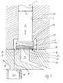
- FIG. 3 shows a control valve 1, which is formed with a control piston 2 according to the invention
- the closing head 4 is formed with a closing head diameter 6 which is larger than the guide diameter 7, on which the control piston 2 is guided in the bore 3.
- the diameter step 27, which corresponds to the return from the closing head diameter 6 to the guide diameter 7, lies in the pressure chamber 12.
- the pressure forces acting on the diameter step 27 increase the sealing force.
- the requirement is that the sealing edge 5 is located on a larger diameter than the guide diameter 7.
- the sealing diameter is formed by the housing wall 13 of the valve plate 14 and a cutting edge of the closing head 4 which projects beyond the end face 10 and which is represented by two mutually inclined bevels 8 and 9.
- the outer chamfer 8 is exposed to the pressure prevailing in the pressure chamber 12 fuel pressure, so that acting here in the opening direction pressure forces act, which are opposite to the force acting on the diameter step 27 compressive forces.
- the sealing edge 5 or the sealing cutting edge is formed by two mutually inclined chamfers, an outer chamfer 8 and an inner chamfer 9.
- the tangents 25 and 26 to the chamfers 9 and 10 in the cutting edge form with the housing wall 12 an angle ⁇ and a Angle ⁇ .
- the angles thus formed are preferably in the range between 0.5 ° and 20 °. In principle, however, any other angles are conceivable.
- the angle between the tangents is preferably 179 to 140 degrees, ie a relatively obtuse angle.
- This relatively obtuse angle has the advantage that, on the one hand, a sharply defined cutting edge is formed with a sealing line which defines the sealing diameter. But the material accumulation lying in front of and behind the cutting edge is also large enough that a high strength is achieved, so that the flattening of the cutting edge during operation is minimized by plastic deformation.
- the angles ⁇ and ⁇ can be chosen to be the same size. By varying the choice of angles, however, a direction of displacement of the sealing diameter can be determined. It can be assumed that the sealing diameter shifts in the direction of the flatter bevel, since the clear distance between chamfer and housing wall stop there is lower and at a plastic flattening of the blade, the flatter bevel sections first in Appendix reach. Thus, if an increase of the sealing diameter in operation is to be achieved, the angle ⁇ at the outer bevel will be smaller than the angle ⁇ at the inner bevel. As a result, the sealing force increases over time because the pressure force acting on the diameter step 27 is compensated to a lesser extent. Conversely, a reduction of the sealing diameter will result if the inner bevel is formed at a smaller angle ⁇ than the angle ⁇ of the outer bevel.
- the displacement of the sealing diameter may also depend on other factors. It is conceivable that the displacement of the sealing diameter due to other influencing factors runs in the opposite direction to the direction described above. Crucial is obviously how big the support of the chamfer is by the material material behind and behind it. The shape of the chamfer can also play a role here.
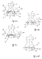
- the chamfers may be formed not only with straight sections but also with a radius such as FIGS. 4a, 4b and 4d demonstrate.
- the outer chamfer is convexly curved and the inner chamfer has a straight section.
- the outer chamfer is formed with a straight section and the inner chamfer 9 with a convex section.
- the chamfers are formed by two straight sections.
- the sealing edge 5 semicircular in cross section.
Landscapes
- Engineering & Computer Science (AREA)
- Chemical & Material Sciences (AREA)
- Combustion & Propulsion (AREA)
- Mechanical Engineering (AREA)
- General Engineering & Computer Science (AREA)
- Physics & Mathematics (AREA)
- Fluid Mechanics (AREA)
- Fuel-Injection Apparatus (AREA)
- Valve Device For Special Equipments (AREA)
- Safety Valves (AREA)
Description
- Es ist bekannt zur Steuerung von Einspritzinjektoren für Brennkraftmaschinen ein Steuerventil zu verwenden, das die Stellbewegungen des Ventilschließglieds steuert. Ein derartiges Steuerventil verfügt über einen hubbeweglichen, Steuerkolben, der zum Beispiel solenoid- oder piezobetätigt sein kann. Der Steuerkolben liegt mit einer Stirnseite im Bereich eines Schließkopfs in einem Druckraum, auf den ein gedrosselter, von einem Steuerraum des Ventilschließglieds ausgehender hochdruckseitiger Zulauf ausmündet, und von dem ein gedrosselter und durch den Steuerkolben gesteuerter Ablauf abgeht. Der Steuerraum des Ventilschließglieds steht in gedrosselter Verbindung mit einer Hochdruckleitung. Die Stellbewegungen des Steuerkolbens bewirken Druckänderungen in dem an das Ventilschließglied angrenzenden Steuerraum und entsprechende Kräfte auf die Rückseite des Ventilschließglieds. Ist der Ablauf des Druckraums geöffnet, wird der Druck im Druckraum abgebaut und gleichzeitig der auf die Rückseite des Ventilschließglieds wirkende Druck erniedrigt, was zum Öffnen des Ventilschließglieds führt. Wird der Ablauf durch den Schließkopf des Steuerkolbens wieder verschlossen, erhöht sich der Druck im Druckraum und zugleich in dem auf der Rückseite des Ventilschließglieds liegenden Steuerraum, was zum Schließen des Ventilschließglieds führt.
- Ein solches Steuerventil ist beispielsweise in der
US 5,934,643 dargestellt. Der Steuerkolben ist an einem einer Gehäusewand gegenüberliegenden Schließkopf mit einem Dichtrand ausgebildet, der, im Anschlag an der Gehäusewand befindlich, einen Druckraum gegen den Mündungsbereich eines Niederdruckanschlusses abdichtet. Der auf dem Umfang des Steuerkolbens gelegene Druckraum steht mit dem Hochdruckanschluss in Verbindung, der zu dem auf der Rückseite des Ventilschließglieds des Injektors liegenden Steuerraum führt, der seinerseits über eine gedrosselte Zuführung mit einem kraftstoffführenden Hochdruckkanal in Verbindung steht. Der auf der Stirnseite des Schließkopfs liegende Dichtrand besitzt in einer Ausgestaltung eine ebene ringförmige Anlagefläche, die sich auf der ebenen Gehäusewand abstützt. In einer anderen Ausgestaltung ist der Dichtrand mit einer Schneide ausgebildet. In dieser letzteren Ausführung wird der Niederdruckanschluss jedoch durch eine Innenbohrung des Steuerkolbens gebildet. Der Außendurchmesser des den Dichtrand tragenden Schließkopfs entspricht offensichtlich dem Führungsdurchmesser des Steuerkolbens. Bei derartigen Ausgestaltungen ergibt sich mit der Zeit eine Verringerung der Schließkraft mit der Folge einer verringerten Dichtwirkung, weil auf Grund des Verschleißes der Dichtkante der dichtende Durchmesser kleiner wird, was ein gänzliches Versagen aufgrund nicht mehr zum Schließen ausreichender Kräfte bewirken kann. Die Verringerung der Schließkraft ist dadurch bedingt, dass eine zusätzliche Fläche mit Kraftstoffdruck beaufschlagt ist, wodurch entgegen der Schließrichtung wirkende Kräfte entstehen, die durch die Steuerventilfeder nicht ausgeglichen werden können. - In der
US 6 364 282 B1 ist ein Steuerventil mit einem Schließkopfdurchmesser offenbart, der größer als der Führungsdurchmesser des Steuerkolbens ist, und die dadurch gebildete Durchmesserstufe liegt im Druckraum. Die Dichtkante (Fig. 9) ist mit zwei gegeneinander geneigten Fasen so ausgebildet, dass sie bei Verschleiß nach innen wandert, was zunehmend Kräfte entgegen der Schließrichtung zur Folge hat, mit dem Nachteil, dass die Dichtkräfte mit zunehmender Betriebsdauer abnehmen. - In der
EP 0 372 712 A1 ist ein Steuerventil dargestellt mit einem bezüglich dem Führungsdurchmesser kleineren Dichtranddurchmesser. Weiterhin ist der Schließkopfdurchmesser größer als der Führungsdurchmesser und die dadurch gebildete Durchmesserstufe liegt im Druckraum. Zur Abdichtung dienen flächige Anlagen, die im Vergleich zu Anlagekanten den Nachteil haben, dass schon kleine Unebenheiten zu Undichtigkeiten führen. - In der
DE 199 40 296 A1 und derDE 101 31 617 A1 sind Steuerventile mit kreisförmigem Verlauf eines Dichtrands dargestellt. - Der Erfindung liegt die Aufgabe zu Grunde, durch Erhöhung der Schließkraft eine zuverlässige Abdichtung auch bei längerer Betriebszeit und Verschleiß der Dichtkante zu gewährleisten.
- Dieses Problem wird durch die im Patentanspruch 1 aufgeführten Merkmale gelöst. Der Schließkopfdurchmesser ist größer ausgeführt als der Führungsdurchmesser des Steuerkolbens, und die Durchmesserstufe, die dem Rücksprung vom Schließkopfdurchmesser auf den Führungsdurchmesser entspricht, ist im Druckraum angeordnet. Dadurch wirkt der im Druckraum anliegende Druck auf die Durchmesserstufe, wodurch eine Kraft in Schließrichtung zusätzlich zur Schließkraft einer Steuerventilfeder erzeugt wird. Voraussetzung ist, dass der dichtende Durchmesser größer als der Führungsdurchmesser ist, was bei einem Schließkopfdurchmesser, wie beschrieben, realisierbar ist. Im Weiteren ist die Stirnfläche des Schließkopfs mit zwei gegeneinander geneigten Fasen ausgebildet, die eine gegenüber der Stirnfläche vorstehende Schneide bilden. Erfindungsgemäß sind die von Tangenten in der Schneide an die Fasen und von der den Anschlag bildenden Gehäusewand eingeschlossenen Winkel α und β und/oder die Form der Fasen derart gewählt, dass sich auf Grund des Verschleißes eine Vergrößerung des dichtenden Durchmessers ergibt. Dadurch wird einer Verkleinerung der Schließkräfte im Betrieb entgegengewirkt.
- Vorteilhafte Ausgestaltungen der Erfindung sind in den Unteransprüchen angegeben.
- Die Ausgestaltung des Dichtrands nach Anspruch 2 mit halbkreisförmigen Verlauf ist besonders günstig im Hinblick auf das Strömungsverhalten und die Vermeidung von Kavitation. Zugleich verspricht diese Ausbildung einen hohen Widerstand gegen Verschleiß bzw. plastische Verformung, weil durch eine große Materialansammlung in der Umgebung unmittelbar vor und hinter der Dichtlinie eine hohe mechanische Festigkeit besteht.
- Gemäß den Unteransprüchen 3 bis 6 weist der Dichtrand eine scharf begrenzte Anlagekante, eine Schneide auf, die aus zwei gegeneinander geneigten Fasen gebildet wird. Die Fasen können dabei aus geraden Abschnitten oder konvexen Abschnitten ausgebildet sein. Konvexe Abschnitte begünstigen das Ein- und Ausströmverhalten und helfen dadurch Kavitation zu vermeiden. Günstigere Durchflussbeiwerte, die dadurch erreicht werden, bieten außerdem die Möglichkeit, den erforderlichen Hub zu verkleinern.
- Gemäß Anspruch 7 beträgt der zwischen den Tangenten an die Fasen in der Schneide eingeschlossene Winkel 90° oder mehr aber weniger als 180°, vorzugsweise 140° bis 179°. Dadurch wird eine scharf begrenzte Anlageschneide gebildet. Andrerseits ist die vor und hinter der Schneide liegende Materialansammlung bei diesen relativ großen Winkeln groß genug, um auch hohe Aufschlagkräfte ohne starke plastische Verformungen des vor und hinter der Schneide liegenden Materials aufnehmen zu können.
- Gemäß den Ansprüchen 8 und 9 betragen die von den Tangenten an die Fasen in der Schneide und von der den Anschlag bildenden Gehäusewand eingeschlossenen Winkel zwischen 0,5° und 20°. Aufgrund des relativ flachen Verlaufs beider Fasen ergibt sich wiederum der Vorteil eines geringen Verschleißes bzw. geringer bleibender Verformungen der den dichtenden Durchmesser darstellenden Schneide. Denn die vor und hinter der Schneide liegende große Materialansammlung bewirkt eine hohe Festigkeit. Dadurch wird eine Verlagerung des dichtenden Durchmessers verringert, so dass die Veränderung der Schließkräfte im Betrieb ebenfalls minimiert wird.
- Durch die Verwendung von gegenüber dem dichtenden Durchmesser außen liegenden Fasen wird ein definierter Spalt gebildet, in dem der Kraftstoffdruck anliegt. Durch Variation der Breite der Fase bzw. des dichtenden Durchmessers kann die an der Durchmesserstufe nach Anspruch 1 in Schließrichtung wirkende Kraft nach Bedarf mehr oder weniger kompensiert werden. Damit besteht eine einfache Möglichkeit, die von der Steuerventilfeder aufzubringende erforderliche Schließkraft durch entsprechende Dimensionierung der Fase anzupassen.
Die Verwendung einer außen liegenden Fase hat auch den Vorteil, dass die Möglichkeit besteht, die Auswirkung des zu erwartenden Verschleißes auf den dichtenden Durchmesser durch eine günstige Wahl der Fasenwinkelkombination so zu beeinflussen, dass sich im Betrieb durch Verschleiß eine Vergrößerung des dichtenden Durchmessers ergibt, was gleichbedeutend einer Erhöhung der Schließkräfte ist. Dieses Ergebnis wird erzielt, wenn die außenliegende Fase nach Anspruch 10 sehr flach und die innen liegende Fase etwas steiler (α<β) verläuft. Bei einer Abflachung der Schneide durch plastische Verformung gelangen nämlich zunächst die außen liegenden Fasenabschnitte mit geringerem lichtem Abstand zur Anlagefläche in Kontakt mit der Anlagefläche der den Dichtsitz bildenden Gehäusewand. - Der Dichtrand liegt nach Anspruch 11 vorzugsweise auf einem Durchmesser, der dem Führungsdurchmesser entspricht oder größer ist. Die Wahl des geeigneten Durchmessers wird durch die durch die Steuerventilfeder und die Druckkräfte erzielbaren Schließkräfte festgelegt. Mit der Wahl des Dichtranddurchmessers werden zugleich auch die Fasenbreiten und damit die auf den Steuerkolben wirkenden Druckkräfte festgelegt.
- Gemäß Anspruch 12 kann der Dichtrand auch auf einem Durchmesser liegen, der kleiner als der Führungsdurchmesser ist.
- Ein Ausführungsbeispiel der Erfindung ist in der Zeichnung dargestellt und wird im Folgenden näher beschrieben.
-
- Fig. 1
- eine Querschnittsansicht eines Injektors mit einem Steuerventil zur Steuerung des Ventilschließglieds;
- Fig. 2
- die Ausführung eines Steuerventils mit einem Steuerkolben nach dem Stand der Technik gemäß
Figur 2a , wobeiFigur 2b ein Detail derFigur 2a darstellt; - Fig. 3
- eine schematische Darstellung eines Steuerventils nach der Erfindung;
- Fig. 4
- stellt, bestehend aus den Teilfiguren 4a bis 4d, verschiedene Ausführungsformen des erfindungsgemäßen Ventilschließkopfs des Steuerventils dar.
- Bei dem in
Figur 1 im Längsschnitt dargestellten Injektor dient ein Steuerventil 1, das mit einem Steuerkolben 2 ausgebildet ist, zur Steuerung der Öffnungs- und Schließbewegungen des Ventilschließglieds 20. Der Steuerraum 19 steht über eine Drossel mit einem Hochdruckkanal in Verbindung, der unter Druck stehenden Kraftstoff enthält. - Durch das Steuerventil 1 kann der Steuerraum 19 druckentlastet werden, um eine Hubbewegung des Ventilschließglieds 20 auszulösen, das dadurch von seinem Ventilsitz 23 abhebt. Die Druckentlastung des Steuerraums 19 wird durch den Steuerkolben 2 des Steuerventil 1 gesteuert. Der Steuerkolben 2 ist mit einem Stellantrieb, zum Beispiel einem Anker eines nicht weiter dargestellten Magnetventils verbunden. Durch Bestromung des Magnetventils hebt der Steuerkolben 2 gegen die Kraft der Steuerventilfeder 24 von seinem Sitz ab und gibt dadurch einen Niederdruckanschluss 16 frei. Mit der Freigabe des Niederdruckanschlusses 16 fällt der Druck in einem Druckraum 12, der über einen Hochdruckanschluss 15 mit dem Steuerraum in Verbindung steht. Nach dem Bestromungsende drückt die Steuerventilfeder 24 den Steuerkolben 2 wieder dichtend an die Ventilplatte 14 an, die eine Gehäusewand 13 des Druckraums 12 darstellt. Der Druck im Druckraum 12 und Steuerraum 19 steigt und damit die am Ventilschließglied 20 in Schließrichtung wirkende Kraft.
- In der
Figur 2 , die aus denFiguren 2a und 2b besteht, ist der Steuerkolben 2 des Steuerventils 1 im Bereich des Dichtsitzes dargestellt. Der Steuerkolben 2 wird in einer Bohrung 3 längsbeweglich geführt. Die Bohrung 3 befindet sich im Steuerventilgehäuse 11. Der Steuerkolben 2 liegt mit einem Teilbereich der Stirnfläche 10 auf der Ventilplatte 14 an und überdeckt dichtend den Niederdruckanschluss 16. In der dargestellten Stellung verhindert der Steuerkolben 2 den Übertritt von über einen Hochdruckanschluss 16 in den Druckraum 12 geführtem Kraftstoff zum Niederdruckanschluss. -
Figur 2b zeigt das inFigur 2a eingekreiste Detail. Nach einer gewissen Betriebsdauer bildet sich durch plastische Verformung in Folge des Aufschlagimpulses oder durch sonstigen Verschleiß, beispielsweise Kavitationserosion, ein Spalt, so dass die tatsächliche Dichtzone 5 nach innen wandert. Da sich damit auch der dichtende Durchmesser nach innen verlagert, entsteht durch den im Spalt wirkenden Kraftstoffdruck eine gegen die Steuerventilfeder 24 gerichtete Druckkraft, welche den Steuerkolben 2 anheben will. Dadurch wird die Dichtkraft geringer, die Dichtsitzleckage steigt mit unzulässiger Änderung der Steuerzeiten und im Extremfall wird der Steuerkolben 2 sogar ganz angehoben, was zum Versagen des Steuerventils 1 führt. -
Figur 3 zeigt ein Steuerventil 1, das mit einem erfindungsgemäßen Steuerkolben 2 ausgebildet ist, dessen Schließkopf 4 mit einem Schließkopfdurchmesser 6 ausgebildet ist, der größer ist als der Führungsdurchmesser 7, auf dem der Steuerkolben 2 in der Bohrung 3 geführt ist. Die Durchmesserstufe 27, die dem Rücksprung vom Schließkopfdurchmesser 6 auf den Führungsdurchmesser 7 entspricht, liegt im Druckraum 12. Durch die an der Durchmesserstufe 27 angreifenden Druckkräfte wird die Dichtkraft erhöht. Voraussetzung ist, dass der Dichtrand 5 auf einem größeren Durchmesser liegt als der Führungsdurchmesser 7. Bei der Wahl des Dichtranddurchmessers 5 ist natürlich darauf zu achten, dass die vom Magneten des Magnetventils aufzubringenden Anzugskräfte die von der Steuerventilfeder 24 und den an der Durchmesserstufe 27 wirkenden Druckkräften übersteigen können. Der dichtende Durchmesser wird von der Gehäusewand 13 der Ventilplatte 14 und einer die Stirnfläche 10 überragenden Schneide des Schließkopfs 4 gebildet, die durch zwei gegeneinander geneigte Fasen 8 und 9 dargestellt wird. Die außenliegende Fase 8 ist dabei dem im Druckraum 12 herrschenden Kraftstoffdruck ausgesetzt, so dass hier in Öffnungsrichtung wirkende Druckkräfte wirken, die den an der Durchmesserstufe 27 wirkenden Druckkräften entgegengesetzt sind. Durch die Fasenbreite der äußeren Fase lassen sich somit variabel, ohne die Steuerventilfeder 24 zu ändern, unterschiedliche Dichtkräfte realisieren. - Des weiteren kann durch unterschiedliche Fasenwinkelkombinationen und Fasenformen bestimmt werden, ob sich der dichtende Durchmesser im Betrieb durch plastische Verformung oder sonstige Verschleißerscheinungen der Dichtschneide vergrößert oder verkleinert. Der Dichtrand 5 bzw. die dichtende Schneide wird durch zwei gegeneinander geneigte Fasen ausgebildet, eine außenliegende Fase 8 und eine innenliegende Fase 9. Die Tangenten 25 und 26 an die Fasen 9 und 10 in der Schneide bilden mit der Gehäusewand 12 einen Winkel α und einen Winkel β. Die derart gebildeten Winkel liegen vorzugsweise im Bereich zwischen 0,5° und 20°. Grundsätzlich sind aber auch beliebige andere Winkel denkbar. Der Winkel zwischen den Tangenten ergibt sich vorzugsweise zu 179 bis 140 Grad, also einem relativ stumpfen Winkel. Dieser relativ stumpfe Winkel hat den Vorteil, dass einerseits eine scharf begrenzte Schneide mit einer Dichtlinie gebildet wird, die den dichtenden Durchmesser definiert. Die vor und hinter der Schneide liegende Materialansammlung ist aber auch groß genug, dass eine hohe Festigkeit erzielt wird, so dass die Abplattung der Schneide im Betrieb durch plastische Verformung minimiert wird.
- Die Winkel α und β können gleich groß gewählt werden. Durch unterschiedliche Wahl der Winkel kann jedoch eine Verlagerungsrichtung des dichtenden Durchmessers festgelegt werden. Es ist davon auszugehen, dass der dichtende Durchmesser sich in Richtung der flacheren Fase verlagert, da der lichte Abstand zwischen Fase und Gehäusewandanschlag dort geringer ist und bei einer plastischen Abplattung der Schneide die flacheren Fasenabschnitte zuerst in Anlage gelangen. Wenn also eine Vergrößerung des dichtenden Durchmessers im Betrieb erzielt werden soll, wird der Winkel α an der äußeren Fase kleiner als der Winkel β an der inneren Fase zu wählen sein. Dadurch erhöht sich im Laufe der Zeit die Dichtkraft, da die an der Durchmesserstufe 27 wirkende Druckkraft in geringerem Maße kompensiert wird. Umgekehrt wird sich dagegen eine Verringerung des dichtenden Durchmessers ergeben, wenn die innere Fase mit einem kleineren Winkel β ausgebildet wird als der Winkel α der äußeren Fase beträgt.
- Die Verlagerung des dichtenden Durchmessers kann aber auch noch von anderen Faktoren abhängen. Es ist denkbar, dass die Verlagerung des dichtenden Durchmessers aufgrund anderer Einflussfaktoren umgekehrt zu oben beschriebener Richtung verläuft. Entscheidend ist offensichtlich, wie groß die Stützung der Fase durch das davor und dahinter anschließende Werkstoffmaterial ist. Dabei kann auch die Form der Fase eine Rolle spielen.
- Die Fasen können nicht nur mit geraden Abschnitten, sondern auch mit einem Radius ausgebildet sein, wie die
Figuren 4a, 4b und 4d zeigen. Bei der Ausbildung nachFigur 4a ist die außenliegende Fase konvex gekrümmt und die innere Fase besitzt einen geraden Abschnitt. Bei der Ausbildung nachFigur 4b ist die außenliegende Fase mit einem geraden Abschnitt und die innenliegende Fase 9 mit einem konvexen Abschnitt ausgebildet. Bei der Ausbildung nachFigur 4c werden die Fasen von zwei geraden Abschnitten gebildet. Bei der Ausbildung nachFigur 4d der Dichtrand 5 halbkreisförmig im Querschnitt. -
- 1
- Steuerventil
- 2
- Steuerkolben
- 3
- Bohrung
- 4
- Schließkopf
- 5
- Dichtrand
- 6
- Schließkopfdurchmesser
- 7
- Führungsdurchmesser
- 8
- Fase, außen
- 9
- Fase, innen
- 10
- Stirnfläche
- 11
- Steuerventilgehäuse
- 12
- Druckraum
- 13
- Gehäusewand
- 14
- Ventilplatte
- 15
- Hochdruckanschluss
- 16
- Niederdruckanschluss
- 17
- Mündung
- 18
- Hochdruckkanal
- 19
- Steuerraum
- 20
- Ventilschließglied
- 21 22
- Ventilfeder
- 23
- Ventilsitz
- 24
- Steuerventilfeder
- 25
- Tangente, innen
- 26
- Tangente, außen
- 27
- Durchmesserstufe
Claims (12)
- Steuerventil (1), mit einem Druckraum (12), der einen Hochdruckanschluss (15) und einen Niederdruckanschluss (16) besitzt, wobei die Mündung (17) des Niederdruckanschlusses (16) in einer den Druckraum (12) begrenzenden, dem Schließkopf (4) eines in einer Bohrung (3) axial verschieblich geführten, durch eine Steuerventilfeder (24) in Schließrichtung belasteten Steuerkolbens (2) gegenüberliegenden Gehäusewand (13) angeordnet ist, die einen Anschlag für den Schließkopf (4) bildet, wobei der Schließkopf (4) eine Stirnfläche (10) mit einem Dichtrand (5) besitzt, mit dem der Schließkopf (4) an der Gehäusewand (13) anliegt und den Mündungsbereich (17) des Niederdruckanschlusses (16) unter Bildung einer Dichtgrenze dichtend überdeckt, und wobei der Schließkopf (4) unter Aufhebung der Dichtgrenze in eine von der Gehäusewand (13) abgehobene Stellung versetzbar ist, wobei der Schließkopfdurchmesser (6) größer ist als der Führungsdurchmesser (7) des Steuerkolbens (2), wobei ferner die Durchmesserstufe (27), die dem Rücksprung vom Schließkopfdurchmesser (6) auf den Führungsdurchmesser (7) entspricht, im Druckraum (12) liegt, und wobei die Stirnfläche (10) des Schließkopfs (4) mit zwei gegeneinander geneigten Fasen (8, 9) ausgebildet ist, die eine gegenüber der Stirnfläche (10) vorstehende Schneide bilden,
dadurch gekennzeichnet,
dass die von Tangenten (25, 26) in der Schneide an die Fasen (8, 9) und von der den Anschlag bildenden Gehäusewand (12) eingeschlossenen Winkel α und β und/oder die Form der Fasen derart gewählt sind, dass sich auf Grund des Verschleißes eine Vergrößerung des dichtenden Durchmessers ergibt. - Steuerventil nach Anspruch 1,
dadurch gekennzeichnet,
dass der Dichtrand (5) einen halbkreisförmigen Verlauf besitzt. - Steuerventil nach Anspruch 1,
dadurch gekennzeichnet,
dass die Fasen (8, 9) aus geraden Abschnitten gebildet sind. - Steuerventil nach Anspruch 1,
dadurch gekennzeichnet,
dass die Fasen (8, 9) aus einem geraden, radial innen liegenden und einem konvexen, radial außen liegenden Abschnitt gebildet sind. - Steuerventil nach Anspruch 1,
dadurch gekennzeichnet,
dass die Fasen (8, 9) aus einem geraden, radial außen liegenden und einem konvexen, radial innen liegenden Abschnitt gebildet sind. - Steuerventil nach Anspruch 1,
dadurch gekennzeichnet,
dass die Fasen (8, 9) aus zwei konvexen Abschnitten gebildet sind. - Steuerventil nach einem der Ansprüche 1 bis 6,
dadurch gekennzeichnet,
dass der zwischen den Tangenten (25, 26) an die Fasen (8, 9) in der Schneide eingeschlossene Winkel 90 Grad oder mehr, aber weniger als 180 Grad, vorzugsweise zwischen 140 und 179 Grad beträgt. - Steuerventil nach einem der Ansprüche 1 bis 7,
dadurch gekennzeichnet,
dass der von der Tangente (26) an die außen liegende Fase (8) in der Schneide und von der den Anschlag bildenden Gehäusewand (12) eingeschlossene Winkel α zwischen 0,5 Grad und 20 Grad beträgt. - Steuerventil nach einem der Ansprüche 1 bis 8,
dadurch gekennzeichnet,
dass der von einer Tangente (25) an die innen liegende Fase (9) in der Schneide und von der den Anschlag bildenden Gehäusewand (12) eingeschlossene Winkel β zwischen 0,5 Grad und 20 Grad beträgt. - Steuerventil nach Anspruch 9,
dadurch gekennzeichnet,
dass der Winkel α (27) kleiner als der Winkel β (28) ist. - Steuerventil nach einem der Ansprüche 1 bis 10,
dadurch gekennzeichnet,
dass der Dichtrand (5) auf einem Durchmesser liegt, der dem Führungsdurchmesser (7) entspricht oder größer ist. - Steuerventil nach einem der Ansprüche 1 bis 10,
dadurch gekennzeichnet,
dass der Dichtrand (5) auf einem Durchmesser liegt, der kleiner als der Führungsdurchmesser (7) ist.
Applications Claiming Priority (2)
| Application Number | Priority Date | Filing Date | Title |
|---|---|---|---|
| DE102004024215A DE102004024215A1 (de) | 2004-05-15 | 2004-05-15 | Steuerventil |
| DE102004024215 | 2004-05-15 |
Publications (2)
| Publication Number | Publication Date |
|---|---|
| EP1600627A1 EP1600627A1 (de) | 2005-11-30 |
| EP1600627B1 true EP1600627B1 (de) | 2008-07-02 |
Family
ID=34936460
Family Applications (1)
| Application Number | Title | Priority Date | Filing Date |
|---|---|---|---|
| EP05010378A Expired - Lifetime EP1600627B1 (de) | 2004-05-15 | 2005-05-12 | Steuerventil |
Country Status (3)
| Country | Link |
|---|---|
| EP (1) | EP1600627B1 (de) |
| AT (1) | ATE399937T1 (de) |
| DE (2) | DE102004024215A1 (de) |
Families Citing this family (12)
| Publication number | Priority date | Publication date | Assignee | Title |
|---|---|---|---|---|
| DE102006026381A1 (de) * | 2006-06-07 | 2007-12-13 | Robert Bosch Gmbh | Kraftstoffinjektor mit Druckübersetzer und niederdruckseitig angeordnetem Piezosteller |
| CN101542103B (zh) * | 2006-10-16 | 2011-12-14 | 甘瑟-许德罗玛格股份公司 | 内燃机的燃油喷射阀 |
| DE102006054063A1 (de) * | 2006-11-16 | 2008-05-21 | Robert Bosch Gmbh | Kraftstoffinjektor |
| DE102007001554A1 (de) * | 2007-01-10 | 2008-07-17 | Robert Bosch Gmbh | Kraftstoffinjektor |
| DE102008005532A1 (de) | 2008-01-22 | 2009-07-23 | Robert Bosch Gmbh | Kraftstoffinjektor, dessen Steuerventilelement einen Stützbereich aufweist |
| DE102008001913A1 (de) * | 2008-05-21 | 2009-11-26 | Robert Bosch Gmbh | Kraftstoff-Injektor |
| DE102008040956A1 (de) * | 2008-08-04 | 2010-02-11 | Robert Bosch Gmbh | Kraftstoff-Injektor |
| AT508049B1 (de) * | 2009-03-17 | 2016-01-15 | Bosch Gmbh Robert | Vorrichtung zum einspritzen von kraftstoff in den brennraum einer brennkraftmaschine |
| DE102009029355A1 (de) * | 2009-09-10 | 2011-03-24 | Robert Bosch Gmbh | Injektor |
| EP2333296B1 (de) * | 2009-12-10 | 2013-04-17 | Delphi Technologies Holding S.à.r.l. | Ventilelement für eine Flüssigkeitsventilanordnung |
| CH710127A1 (de) * | 2014-09-17 | 2016-03-31 | Ganser Crs Ag | Brennstoffeinspritzventil für Verbrennungskraftmaschinen. |
| GB2559560B (en) * | 2017-02-08 | 2020-06-17 | Delphi Tech Ip Ltd | Control valve arrangement for a dual fuel injector |
Family Cites Families (16)
| Publication number | Priority date | Publication date | Assignee | Title |
|---|---|---|---|---|
| DE1550299A1 (de) * | 1966-07-01 | 1970-01-29 | Leybold Heraeus Gmbh & Co Kg | Hochvakuumventil,insbesondere Ultrahochvakuumventil |
| RU1839701C (ru) * | 1988-01-20 | 1993-12-30 | Ханс Отто Мит (DE) | Клапан с защитным элементом дл уплотнени |
| GB8828160D0 (en) * | 1988-12-02 | 1989-01-05 | Lucas Ind Plc | Fluid control valve |
| JP3017816B2 (ja) * | 1991-02-20 | 2000-03-13 | 清原 まさ子 | 流体制御器 |
| JP2952174B2 (ja) * | 1994-12-27 | 1999-09-20 | 田中機工株式会社 | ブリーザ弁等の弁座 |
| DE19516885C1 (de) * | 1995-05-09 | 1996-10-24 | Elektroteile Gmbh | Pneumatikventil |
| GB9526522D0 (en) * | 1995-12-23 | 1996-02-28 | Lucas Ind Plc | Valve arrangement |
| US5899435A (en) * | 1996-09-13 | 1999-05-04 | Westinghouse Air Brake Co. | Molded rubber valve seal for use in predetermined type valves, such as, a check valve in a regenerative desiccant air dryer |
| DE19837333A1 (de) * | 1998-08-18 | 2000-02-24 | Bosch Gmbh Robert | Steuereinheit zur Steuerung des Druckaufbaus in einer Pumpeneinheit |
| US6364282B1 (en) * | 1998-12-04 | 2002-04-02 | Caterpillar Inc. | Hydraulically actuated fuel injector with seated pin actuator |
| DE19940296A1 (de) * | 1999-08-25 | 2001-03-01 | Bosch Gmbh Robert | Ventil |
| JP2002071038A (ja) * | 2000-08-25 | 2002-03-08 | Kubota Corp | 弁体シート |
| JP3425938B2 (ja) * | 2000-12-14 | 2003-07-14 | 入江工研株式会社 | ゲート弁 |
| DE10131617A1 (de) * | 2001-06-29 | 2003-01-23 | Bosch Gmbh Robert | Kraftstoffinjektor-Schaltventil zur Druckentlastung/Belastung eines Steuerraumes |
| US6708951B2 (en) * | 2002-01-17 | 2004-03-23 | Westinghouse Air Brake Technologies Corporation | Annular sealing device having a positive stop means for use in a valve member |
| DE10251587B4 (de) * | 2002-11-06 | 2017-03-09 | Robert Bosch Gmbh | Ventil zum Steuern eines Fluidstroms |
-
2004
- 2004-05-15 DE DE102004024215A patent/DE102004024215A1/de not_active Withdrawn
-
2005
- 2005-05-12 AT AT05010378T patent/ATE399937T1/de active
- 2005-05-12 EP EP05010378A patent/EP1600627B1/de not_active Expired - Lifetime
- 2005-05-12 DE DE502005004557T patent/DE502005004557D1/de not_active Expired - Lifetime
Also Published As
| Publication number | Publication date |
|---|---|
| DE102004024215A1 (de) | 2005-12-08 |
| EP1600627A1 (de) | 2005-11-30 |
| DE502005004557D1 (de) | 2008-08-14 |
| ATE399937T1 (de) | 2008-07-15 |
Similar Documents
| Publication | Publication Date | Title |
|---|---|---|
| EP2171258B1 (de) | Steuerventil für ein kraftstoffeinspritzventil | |
| EP1259729B1 (de) | Magnetventil zur steuerung eines einspritzventils einer brennkraftmaschine | |
| DE102008001330A1 (de) | Kraftstoffeinspritzventil für Brennkraftmaschinen | |
| EP2769129B1 (de) | Vorsteuerstufe für ein proportional gesteuertes hochdruck-hydraulikventil | |
| DE10023621A1 (de) | Kraftstoffeinspritzsystem für Brennkraftmaschinen | |
| EP1882122B1 (de) | Ventil, insbesondere proportional-druckbegrenzungsventil | |
| DE102006000035B4 (de) | Fluideinspritzventil | |
| EP1600627A1 (de) | Steuerventil | |
| EP1983239A1 (de) | Ventil | |
| EP1952032B1 (de) | Hydraulisches/pneumatisches steuerventil mit fail-safe funktion | |
| EP1456524B1 (de) | Einspritzinjektor für brennkraftmaschinen | |
| EP2867520B1 (de) | Kraftstoffhochdruck-kolbenpumpe | |
| EP1611358A1 (de) | Stetig verstellbares wegeventil | |
| EP1208297B1 (de) | Einspritzventil für eine verbrennungskraftmaschine | |
| EP1952012B1 (de) | Einspritzinjektor | |
| WO2007104391A1 (de) | Hydraulische ventilanordnung | |
| DE102004026683B4 (de) | Hydraulische Ventileinrichtung | |
| EP2138709A1 (de) | Direkt betätigter Kraftstoffinjektor | |
| DE19928991C1 (de) | Druckbeaufschlagtes Steuermodul mit reduzierter Leckage | |
| EP3184803B1 (de) | Kraftstoffinjektor | |
| DE102015117854B4 (de) | Kraftstoff-Einspritzinjektor mit einer verstellbaren Düsennadel | |
| DE29818405U1 (de) | Hydraulische Steuereinrichtung | |
| AT519300B1 (de) | Längenverstellbare Pleuelstange mit Zylinder-Kolben-Einheit mit Spaltdichtung und dehnbarem Kolbenkragen | |
| DE102012213535A1 (de) | Kraftstoffinjektor | |
| DE102008040840A1 (de) | Hydraulisch gesteuerter Aktor |
Legal Events
| Date | Code | Title | Description |
|---|---|---|---|
| PUAI | Public reference made under article 153(3) epc to a published international application that has entered the european phase |
Free format text: ORIGINAL CODE: 0009012 |
|
| 17P | Request for examination filed |
Effective date: 20050512 |
|
| AK | Designated contracting states |
Kind code of ref document: A1 Designated state(s): AT BE BG CH CY CZ DE DK EE ES FI FR GB GR HU IE IS IT LI LT LU MC NL PL PT RO SE SI SK TR |
|
| AX | Request for extension of the european patent |
Extension state: AL BA HR LV MK YU |
|
| AKX | Designation fees paid |
Designated state(s): AT BE BG CH CY CZ DE DK EE ES FI FR GB GR HU IE IS IT LI LT LU MC NL PL PT RO SE SI SK TR |
|
| 17Q | First examination report despatched |
Effective date: 20060710 |
|
| 17Q | First examination report despatched |
Effective date: 20060710 |
|
| GRAP | Despatch of communication of intention to grant a patent |
Free format text: ORIGINAL CODE: EPIDOSNIGR1 |
|
| GRAS | Grant fee paid |
Free format text: ORIGINAL CODE: EPIDOSNIGR3 |
|
| GRAA | (expected) grant |
Free format text: ORIGINAL CODE: 0009210 |
|
| AK | Designated contracting states |
Kind code of ref document: B1 Designated state(s): AT BE BG CH CY CZ DE DK EE ES FI FR GB GR HU IE IS IT LI LT LU MC NL PL PT RO SE SI SK TR |
|
| REG | Reference to a national code |
Ref country code: GB Ref legal event code: FG4D Free format text: NOT ENGLISH |
|
| RIN1 | Information on inventor provided before grant (corrected) |
Inventor name: SCHEIBE, WOLFGANG, DR.-ING. Inventor name: KOCH, HANS-JOACHIM |
|
| REG | Reference to a national code |
Ref country code: CH Ref legal event code: EP |
|
| REF | Corresponds to: |
Ref document number: 502005004557 Country of ref document: DE Date of ref document: 20080814 Kind code of ref document: P |
|
| REG | Reference to a national code |
Ref country code: IE Ref legal event code: FG4D Free format text: LANGUAGE OF EP DOCUMENT: GERMAN |
|
| PG25 | Lapsed in a contracting state [announced via postgrant information from national office to epo] |
Ref country code: SI Free format text: LAPSE BECAUSE OF FAILURE TO SUBMIT A TRANSLATION OF THE DESCRIPTION OR TO PAY THE FEE WITHIN THE PRESCRIBED TIME-LIMIT Effective date: 20080702 |
|
| PG25 | Lapsed in a contracting state [announced via postgrant information from national office to epo] |
Ref country code: NL Free format text: LAPSE BECAUSE OF FAILURE TO SUBMIT A TRANSLATION OF THE DESCRIPTION OR TO PAY THE FEE WITHIN THE PRESCRIBED TIME-LIMIT Effective date: 20080702 |
|
| NLV1 | Nl: lapsed or annulled due to failure to fulfill the requirements of art. 29p and 29m of the patents act | ||
| PG25 | Lapsed in a contracting state [announced via postgrant information from national office to epo] |
Ref country code: PT Free format text: LAPSE BECAUSE OF FAILURE TO SUBMIT A TRANSLATION OF THE DESCRIPTION OR TO PAY THE FEE WITHIN THE PRESCRIBED TIME-LIMIT Effective date: 20081202 Ref country code: LT Free format text: LAPSE BECAUSE OF FAILURE TO SUBMIT A TRANSLATION OF THE DESCRIPTION OR TO PAY THE FEE WITHIN THE PRESCRIBED TIME-LIMIT Effective date: 20080702 Ref country code: ES Free format text: LAPSE BECAUSE OF FAILURE TO SUBMIT A TRANSLATION OF THE DESCRIPTION OR TO PAY THE FEE WITHIN THE PRESCRIBED TIME-LIMIT Effective date: 20081013 Ref country code: IS Free format text: LAPSE BECAUSE OF FAILURE TO SUBMIT A TRANSLATION OF THE DESCRIPTION OR TO PAY THE FEE WITHIN THE PRESCRIBED TIME-LIMIT Effective date: 20081102 |
|
| REG | Reference to a national code |
Ref country code: IE Ref legal event code: FD4D |
|
| PG25 | Lapsed in a contracting state [announced via postgrant information from national office to epo] |
Ref country code: BG Free format text: LAPSE BECAUSE OF FAILURE TO SUBMIT A TRANSLATION OF THE DESCRIPTION OR TO PAY THE FEE WITHIN THE PRESCRIBED TIME-LIMIT Effective date: 20081002 |
|
| PG25 | Lapsed in a contracting state [announced via postgrant information from national office to epo] |
Ref country code: IE Free format text: LAPSE BECAUSE OF FAILURE TO SUBMIT A TRANSLATION OF THE DESCRIPTION OR TO PAY THE FEE WITHIN THE PRESCRIBED TIME-LIMIT Effective date: 20080702 Ref country code: DK Free format text: LAPSE BECAUSE OF FAILURE TO SUBMIT A TRANSLATION OF THE DESCRIPTION OR TO PAY THE FEE WITHIN THE PRESCRIBED TIME-LIMIT Effective date: 20080702 Ref country code: EE Free format text: LAPSE BECAUSE OF FAILURE TO SUBMIT A TRANSLATION OF THE DESCRIPTION OR TO PAY THE FEE WITHIN THE PRESCRIBED TIME-LIMIT Effective date: 20080702 |
|
| PLBE | No opposition filed within time limit |
Free format text: ORIGINAL CODE: 0009261 |
|
| STAA | Information on the status of an ep patent application or granted ep patent |
Free format text: STATUS: NO OPPOSITION FILED WITHIN TIME LIMIT |
|
| PG25 | Lapsed in a contracting state [announced via postgrant information from national office to epo] |
Ref country code: SK Free format text: LAPSE BECAUSE OF FAILURE TO SUBMIT A TRANSLATION OF THE DESCRIPTION OR TO PAY THE FEE WITHIN THE PRESCRIBED TIME-LIMIT Effective date: 20080702 Ref country code: RO Free format text: LAPSE BECAUSE OF FAILURE TO SUBMIT A TRANSLATION OF THE DESCRIPTION OR TO PAY THE FEE WITHIN THE PRESCRIBED TIME-LIMIT Effective date: 20080702 Ref country code: CZ Free format text: LAPSE BECAUSE OF FAILURE TO SUBMIT A TRANSLATION OF THE DESCRIPTION OR TO PAY THE FEE WITHIN THE PRESCRIBED TIME-LIMIT Effective date: 20080702 |
|
| 26N | No opposition filed |
Effective date: 20090403 |
|
| BERE | Be: lapsed |
Owner name: L'ORANGE G.M.B.H. Effective date: 20090531 |
|
| PG25 | Lapsed in a contracting state [announced via postgrant information from national office to epo] |
Ref country code: MC Free format text: LAPSE BECAUSE OF NON-PAYMENT OF DUE FEES Effective date: 20090531 |
|
| PG25 | Lapsed in a contracting state [announced via postgrant information from national office to epo] |
Ref country code: SE Free format text: LAPSE BECAUSE OF FAILURE TO SUBMIT A TRANSLATION OF THE DESCRIPTION OR TO PAY THE FEE WITHIN THE PRESCRIBED TIME-LIMIT Effective date: 20081002 |
|
| REG | Reference to a national code |
Ref country code: FR Ref legal event code: ST Effective date: 20100129 |
|
| PG25 | Lapsed in a contracting state [announced via postgrant information from national office to epo] |
Ref country code: FR Free format text: LAPSE BECAUSE OF NON-PAYMENT OF DUE FEES Effective date: 20090602 |
|
| PG25 | Lapsed in a contracting state [announced via postgrant information from national office to epo] |
Ref country code: PL Free format text: LAPSE BECAUSE OF FAILURE TO SUBMIT A TRANSLATION OF THE DESCRIPTION OR TO PAY THE FEE WITHIN THE PRESCRIBED TIME-LIMIT Effective date: 20080702 |
|
| PG25 | Lapsed in a contracting state [announced via postgrant information from national office to epo] |
Ref country code: BE Free format text: LAPSE BECAUSE OF NON-PAYMENT OF DUE FEES Effective date: 20090531 |
|
| PG25 | Lapsed in a contracting state [announced via postgrant information from national office to epo] |
Ref country code: GR Free format text: LAPSE BECAUSE OF FAILURE TO SUBMIT A TRANSLATION OF THE DESCRIPTION OR TO PAY THE FEE WITHIN THE PRESCRIBED TIME-LIMIT Effective date: 20081003 |
|
| PG25 | Lapsed in a contracting state [announced via postgrant information from national office to epo] |
Ref country code: LU Free format text: LAPSE BECAUSE OF NON-PAYMENT OF DUE FEES Effective date: 20090512 |
|
| PG25 | Lapsed in a contracting state [announced via postgrant information from national office to epo] |
Ref country code: HU Free format text: LAPSE BECAUSE OF FAILURE TO SUBMIT A TRANSLATION OF THE DESCRIPTION OR TO PAY THE FEE WITHIN THE PRESCRIBED TIME-LIMIT Effective date: 20090103 |
|
| PG25 | Lapsed in a contracting state [announced via postgrant information from national office to epo] |
Ref country code: TR Free format text: LAPSE BECAUSE OF FAILURE TO SUBMIT A TRANSLATION OF THE DESCRIPTION OR TO PAY THE FEE WITHIN THE PRESCRIBED TIME-LIMIT Effective date: 20080702 |
|
| PG25 | Lapsed in a contracting state [announced via postgrant information from national office to epo] |
Ref country code: CY Free format text: LAPSE BECAUSE OF FAILURE TO SUBMIT A TRANSLATION OF THE DESCRIPTION OR TO PAY THE FEE WITHIN THE PRESCRIBED TIME-LIMIT Effective date: 20080702 |
|
| PGFP | Annual fee paid to national office [announced via postgrant information from national office to epo] |
Ref country code: DE Payment date: 20120523 Year of fee payment: 8 Ref country code: CH Payment date: 20120523 Year of fee payment: 8 |
|
| PGFP | Annual fee paid to national office [announced via postgrant information from national office to epo] |
Ref country code: GB Payment date: 20120522 Year of fee payment: 8 Ref country code: FI Payment date: 20120511 Year of fee payment: 8 |
|
| PGFP | Annual fee paid to national office [announced via postgrant information from national office to epo] |
Ref country code: IT Payment date: 20120525 Year of fee payment: 8 |
|
| PGFP | Annual fee paid to national office [announced via postgrant information from national office to epo] |
Ref country code: AT Payment date: 20120511 Year of fee payment: 8 |
|
| REG | Reference to a national code |
Ref country code: CH Ref legal event code: PL |
|
| REG | Reference to a national code |
Ref country code: AT Ref legal event code: MM01 Ref document number: 399937 Country of ref document: AT Kind code of ref document: T Effective date: 20130531 |
|
| GBPC | Gb: european patent ceased through non-payment of renewal fee |
Effective date: 20130512 |
|
| PG25 | Lapsed in a contracting state [announced via postgrant information from national office to epo] |
Ref country code: DE Free format text: LAPSE BECAUSE OF NON-PAYMENT OF DUE FEES Effective date: 20131203 Ref country code: CH Free format text: LAPSE BECAUSE OF NON-PAYMENT OF DUE FEES Effective date: 20130531 Ref country code: AT Free format text: LAPSE BECAUSE OF NON-PAYMENT OF DUE FEES Effective date: 20130531 Ref country code: LI Free format text: LAPSE BECAUSE OF NON-PAYMENT OF DUE FEES Effective date: 20130531 |
|
| REG | Reference to a national code |
Ref country code: DE Ref legal event code: R119 Ref document number: 502005004557 Country of ref document: DE Effective date: 20131203 |
|
| PG25 | Lapsed in a contracting state [announced via postgrant information from national office to epo] |
Ref country code: FI Free format text: LAPSE BECAUSE OF NON-PAYMENT OF DUE FEES Effective date: 20130512 Ref country code: IT Free format text: LAPSE BECAUSE OF NON-PAYMENT OF DUE FEES Effective date: 20130512 |
|
| PG25 | Lapsed in a contracting state [announced via postgrant information from national office to epo] |
Ref country code: GB Free format text: LAPSE BECAUSE OF NON-PAYMENT OF DUE FEES Effective date: 20130512 |