EP1600339A2 - Aufnahmevorrichtung für ein Sicherheitsnetz - Google Patents
Aufnahmevorrichtung für ein Sicherheitsnetz Download PDFInfo
- Publication number
- EP1600339A2 EP1600339A2 EP05010114A EP05010114A EP1600339A2 EP 1600339 A2 EP1600339 A2 EP 1600339A2 EP 05010114 A EP05010114 A EP 05010114A EP 05010114 A EP05010114 A EP 05010114A EP 1600339 A2 EP1600339 A2 EP 1600339A2
- Authority
- EP
- European Patent Office
- Prior art keywords
- housing
- receiving device
- holder
- energy
- engages
- Prior art date
- Legal status (The legal status is an assumption and is not a legal conclusion. Google has not performed a legal analysis and makes no representation as to the accuracy of the status listed.)
- Granted
Links
Images


Classifications
-
- B—PERFORMING OPERATIONS; TRANSPORTING
- B60—VEHICLES IN GENERAL
- B60R—VEHICLES, VEHICLE FITTINGS, OR VEHICLE PARTS, NOT OTHERWISE PROVIDED FOR
- B60R21/00—Arrangements or fittings on vehicles for protecting or preventing injuries to occupants or pedestrians in case of accidents or other traffic risks
- B60R21/02—Occupant safety arrangements or fittings, e.g. crash pads
- B60R21/06—Safety nets, transparent sheets, curtains, or the like, e.g. between occupants and glass
Definitions
- the invention relates to a receiving device for a safety net to protect a passenger compartment of station wagon versus the loading area according to the preamble of claim 1.
- Such recording devices are well known and have a housing which rotatably receives a winding shaft accommodates which is fastened with a longitudinal edge a safety net, which by a Slot in the housing either extendable or in the housing is to retract.
- the housing has at a left and right end Attachment sections, each in a stationary in the car Recording device for fixing the housing are to be used. In a use position of the receiving device in the hold of a Combi cars are the mounting portions in the stationary receiving device locked positioned so that an independent or unintentional Loosening is prevented.
- the attachment sections are solid provided on the housing of the receiving device to the housing to hold in the use position and the forces when extending and retracting the safety net and any holding forces, which arise when an object is being caught by the safety net can.
- the invention is therefore based on the object, a recording device for a safety net to protect a passenger compartment of Combined cars to create over the cargo space in a rear-end collision fulfills the protective function.
- the inventive design of the receiving device has at least between the housing and a mounting portion or between at least two housing sections at least in the axial longitudinal direction the housing acting energy-absorbing agent.
- the housing acting energy-absorbing agent allows the impact energy to be translated into deformation work and a break of the cradle respectively uncontrolled release of a mounting portion of the housing or from a fixed receptacle or a break between prevents the attachment portion and the housing.
- the energy-consuming means allow at least in the axial longitudinal direction of the housing a length compensation, whereby the expansion of the C-pillar balanced in a collision of the vehicle becomes.
- the energy-absorbing means are provided on a holder, which engages an end portion of the housing and first a Attachment section includes.
- This embodiment has the advantage on top of that, the conventional housing to accommodate a winding shaft and a safety net can be used and to the respective free ends of the housing arranged holder the energy-consuming Means include.
- the energy-consuming means to a housing are provided, at the end portions of a mounting portion exhibiting holder attacks.
- This embodiment has the Advantage on that a uniform housing with energy-consuming means is provided, so that a unified housing with different Holders can be equipped to stand for different stationary Recording devices used in the cargo area of estate cars to become.
- the energy-consuming means between a Attachment section and a housing portion of the holder are provided.
- This allows the housing to accommodate the winding shaft maintain their original shape and form.
- the adaptation The energy-consuming agent may vary depending on the installation situation be made and adapted.
- the attachment sections and at least one housing portion of the holder are usually for a positive and / or non-positive connection for releasably attaching the Receiving device formed so that the energy-absorbing means at the same time integrated in the adjustment. This will give you the flexibility the modular design increased.
- the energy-consuming means comprise at least one latching element, which engages in a recording and when exceeding a predetermined Force at least in the axial longitudinal direction of the housing from the recording is released, torn or deformed.
- This will allow that from a certain impact energy, a corresponding Widening of the body in the area of the C-pillars has the result energy-absorbing agents are used, causing the receiving device Stretchable or length compensatable along its longitudinal axis is.
- the tearing or deforming is advantageously ensured by the guide portion of the holder, that the holder surrounds the free end portion of the housing and / or guided therein, so that a complete release of the housing from the holder is not given.
- the at least one latching element is preferably on one Holder provided, which engages in a receptacle of the housing.
- the locking element may be provided on the housing, which in a Recording of the holder engages. With several locking elements can also be provided any combination.
- the at least one locking element on the guide portion the holder is provided. This will allow after the Releasing the at least one locking element from the receptacle an end portion the housing is still surrounded by the holder and a longitudinally displaceable embodiment for receiving the at least short-term Expansion of the C-pillars assumes.
- At least two locking elements in the axial longitudinal direction of the housing are provided spaced from each other, depending on the one after the other from the receptacle, break free or deform.
- This can be the energy-consuming means have a stepped or a continuously increasing force, the counteracts the expansion of the C-pillars. An increased security for Conversion of the force acting through the expansion force in deformation work is possible.
- the at least two locking elements can advantageously in a common median plane or offset from one another be provided.
- the at least one latching element at least one stop is assigned, after the free coming of at least one locking element from the recording an end position in the axial direction of the at least a holder to the housing or the housing sections to each other guaranteed.
- This makes it possible for a larger force on the receiving device, on the one hand by the widening the C-pillars and on the other hand by an optionally sagging of the housing due to the retention of a object thrown against the safety net which Protective function is fulfilled.
- This at least one attack secures the Holder to the housing after a rear-end collision.
- the stop is advantageously guided in a slot-shaped recess.
- the holder is according to a preferred embodiment as an end piece formed, with its guide portion, the free end of the housing encompasses or intervenes in sections, at least one Detent element and at least one stop, which in each case in a Engage recess of the housing.
- This allows the holder as End cap be formed, which by pushing in a simple manner can be positioned to the housing.
- the mounting of the holder in the end position takes place in a simple manner by snapping into an end position, since during the sliding of the tail on the housing, the locking elements and the stop widen to a final position in the receptacle intervene.
- the holder which is designed as an end piece and at least a latching element, the at least one stop and at least one Attachment section comprises, as an injection molded part made of plastic, in particular an impact-resistant plastic, is formed.
- plastic in particular an impact-resistant plastic
- the holder can also be used as a cast or die-cast part from a casting alloy, such as an aluminum alloy, be prepared.
- the housing is formed as an extruded profile.
- the housing has an inherent rigidity which includes a simple geometric shape and allows that the housing advantageously in one piece across the entire vehicle width extends.
- the storage of the winding shaft in the Housing is provided and the bearing is preferably a frontal Graduation forms.
- This can be a prefabrication of the housing with the Equipping the winding shaft, the safety net and a spring motor or the like may be provided.
- the spring engine is pulled out biased the safety net, so that a restoring force winding supports the blind or independently and makes the safety net in a rolled up position.
- the in the case arranged components form an assembly, which by fitting of corresponding holders to various stationary receiving devices are customizable.
- energy-consuming means at least one deformation body include.
- deformation bodies have the advantage that depending on the widening of the C-pillars a deformation work he follows.
- the deformation body is advantageously at least as a resilient Element formed. This allows the holder under bias be positioned to the housing, wherein in the event of an impact a length compensation by reducing the path of the elastic element is possible.
- spring-elastic elements spring packages Single springs, such as coil springs, disc springs, rubber elastic Body or the like may be provided.
- this is formed by a tube or a sleeve, the made of plastic or metal.
- This tube or the sleeve interacts with an engaging element on the holder, which is the tube or the sleeve deformed.
- an engaging element on the holder which is the tube or the sleeve deformed.
- a pull rod projections be present as attack elements, compared to an inner diameter of the tube or sleeve and to perform the deformation work an expansion of the tube or sleeve cause.
- the deformation body as a tube or sleeve of a foamed Plastic, in particular of foamed metals or Metal alloys, is formed.
- foamed Plastic in particular of foamed metals or Metal alloys
- These metal foams can be opened or closed-cell design.
- Foams are preferred an aluminum alloy used, for example, as a casting alloy or wrought alloy are made.
- one or more expansion elements in particular Expansion bolts, to be inserted between a mounting section and a free end of the housing are arranged.
- expansion elements also allow a length compensation when Expansion of the C-pillars during a collision. More elastic Elements can be used.
- a bellows provided.
- This bellows can advantageously accommodate largely incompressible media, for damping during stretching or length change perform the recording device.
- largely incompressible Media can be both liquid, gel and gaseous media be used.
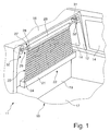
- FIG. 1 shows a section of a rear region 11 of a station wagon shown.
- the rear area 11 is laterally by a respective C-pillar 12th limited, at which windows 14 connect.
- the C-pillar 12 is followed by a roof 16.
- a loading area 17 is provided in the lower part of the C-pillar 12.
- a cargo space is through the Roof 16, the cargo bed 17 and the C-pillars 12 and a rear seat 19 limited.
- a receiving device 21 attached to a safety net assembly 22.
- this receiving device 21 is a winding shaft 25 ( Figure 3) rotatably mounted on the with a longitudinal edge a safety net 23rd is fixed, through a slot 24 in the receiving device 21st optionally removable or in the receiving device 21 is to be retracted.
- the safety net 23 has a front edge running parallel to the winding shaft 25 26 on, for example, via a loop to the fastening device 27 is arranged.
- the fastening device 27 comprises a Pull rod 28 and each end to the ends arranged on both sides holding members 29.
- the holding members 29 have mushroom-shaped at their free ends Heads 31, which can be used in receptacles 32.
- the pictures 32 are stationary in the transition region between the C-pillar 12 and the Roof 16 arranged.
- In the extended position shown in Figure 1 of the safety net 23 is the loading space 18 through the safety net separated to the interior of the occupants.
- FIG. 2 shows a view into the loading space 18 of a station wagon.
- the receiving device 21 is provided with left and right ends each attached to the ends associated C-pillar 12.
- the C-pillars 12 expand as shown in FIG Figure 2 is shown by dashed lines 34.
- the C-pillars 12 exert tensile forces on the receiving device 21.
- Figures 3 to 5 illustrated inventive recording device 21 and by way of example an alternative embodiment according to FIG. 6 intended.
- FIG. 3 is a schematic view of the receiving device according to the invention 21, which includes a housing 36, to an end portion 37 receives a holder 39.
- This holder 39 the is shown in a sectional view according to Figure 4, comprises a Attachment portion 41, which on a stationary receiving device 42 is provided.
- the stationary receiving device 42 is in the range the C-pillar 12 is positioned.
- the attachment portion 41 is preferable by a locking, not shown in the receiving device 42 detachably fixed.
- the holder 39 has a cross-section of the Housing 36 adapted cross-section, which is used to encompass the end portion 37 of the housing 36 is formed.
- the holder 39 is to the C-pillar 12 is formed closed and has an open end 44th for embracing the housing 12. At least in this end area 44, the slot 24 extends so that the safety net 23 via the maximum width of the cargo space 18 extends.
- At least one latching element 46 is provided, which is arranged in a recess 47 as soon as the holder 39 in the correct position on the free end portion 37 of the housing 36 is positioned is. At least these components form in a first embodiment the energy-consuming means.
- the end region 44 comprises Furthermore, at least one stop 51, which in a slot-shaped Recess 52 is slidably received.
- the locking element 46 and the stopper 51 are at a predetermined distance from each other arranged, the distance of the recess 47 from the free end portion 37 corresponds.
- the at least one locking element 44 and / or the at least one stop 51 can alternatively also be attached to a tab be provided in the guide section 56. This is an exact positioning of the holder 39 is given as an end to the housing 36. One Rattling or slight displacement from the housing 36 to the holder 39 is prevented.
- Winding shaft 25 which is rotatably supported by a bearing 54.
- This camp advantageously forms a conclusion to the housing 54 36.
- the outer circumference of this bearing disc preferably corresponds to Cross section of the housing 36.
- the safety net 23 intended to be wound up and unwound.
- the receiving device 21 is shown after a collision.
- the C-pillars 12 have been widened at least in the short term or expanded.
- a displacement of the holder 39 opposite the housing 36 in the axial longitudinal direction of the housing 36 is a length compensation he follows.
- the holder 39 is guided in a sliding seat, the by a guide portion 56, the slot-shaped recess 52nd and the stopper 51 is formed.
- a release of at least one Locking element 46 from the recess 47 After exceeding a certain Force due to the expansion of the C-pillars 18 in the receiving device 22 is initiated, a release of at least one Locking element 46 from the recess 47. This will stop 51 through the guide portion in the slot-shaped recess 52 of the housing 36 slidably guided to the end portion 37.
- the stop 51 has a perpendicular to the slot-shaped recess 52 extending body edge, the maximum displacement between Holder 39 and housing 36 limited.
- the length of the slit-shaped Recess 52 is designed such that the maximum provided Expansion of the C-pillars 12 is compensated.
- the at least one locking element 46 may alternatively come to free sheared off or demolished from the recess 47. alternative can be provided that a deformation takes place.
- the Holder 39 formed as an injection molded part.
- the holder 39 from an aluminum die-cast or a metallic housing provided be.
- FIG. 6 shows an alternative embodiment of the invention Receiving device 21 shown in FIG 3.
- the holder 39 has As energy-consuming means a deformation body 61 on.
- This deformation body 61 is a length compensation A during expansion the C-pillars 12 while maintaining the correct arrangement of the Receiving device 21 to the loading space 18 achieved.
- a holder 39, the positioned with its mounting portion 41 in the receiving device 42 is initially equipped with a sleeve-shaped member 64.
- This component 64 has an annular portion 66, whose Opening a pull rod 67 penetrates, which is arranged on the holder 39 is.
- This tension rod 67 receives the deformation body 61.
- a disc-shaped element 68 on the tension rod 67 positioned and fixed.
- the holder 39 with the component 41 is attached to the end portion 37 of the housing 36.
- Locking elements 46 engage in recesses 47 of the housing 36 and fix the holder 39 in an end position.
- the deformation body 61 is provided that this formed as a rubber-elastic ring element is. This makes it possible that a stretchable receiving device 21 is formed, the self-contained in its initial state returns. Furthermore, it may alternatively be provided that the Deformation body 61 as a compression spring or coil spring or plate spring packets or the like is formed. Also by that is the Holder 39 length compensating and can be adjusted according to the required Return to its original position.
- the deformation body 61 is formed by compressible media.
- An analogous effect to the aforementioned embodiments is achieved.
- the deformation body 61st is formed from irreversible energy-consuming means.
- Particularly preferred are open or closed-pore cast alloys or wrought alloys.
- the deformation body 61 may also be provided, for example, by expansion elements, For example, expansion bolts, be formed.
- expansion elements For example, expansion bolts.
- the construction between the holder 39 and the sleeve-shaped component 64 is adapted in such a way that a tensile effect is applied to the expansion screws.
- the housing consists of at least two housing sections, with between the at least two housing sections a holder is provided which in combination with the housing sections energy-absorbing agents includes.
- this holder may be sleeve-shaped and at least one latching element 46 and preferably a stop 51 analogous to the end portion 44 of the holder 39 having on a End portion 37 of the housing section attack or mirror-symmetrical are formed, so that in each case at an end portion of each other associated housing sections, the locking elements and preferably Attack attacks of a holder.
- This embodiment may also be in Combination with the embodiments shown in Figures 3 to 6 be provided.
Landscapes
- Engineering & Computer Science (AREA)
- Mechanical Engineering (AREA)
- Emergency Lowering Means (AREA)
- Vehicle Step Arrangements And Article Storage (AREA)
- Vibration Dampers (AREA)
- Fittings On The Vehicle Exterior For Carrying Loads, And Devices For Holding Or Mounting Articles (AREA)
- Fire Alarms (AREA)
- Harvester Elements (AREA)
Abstract
Description
- Figur 1
- eine perspektivische Darstellung einer Aufnahmevorrichtung für ein Sicherheitsnetz in einem Laderaum eines Kombi PKWs,
- Figur 2
- eine schematische Ansicht in einen Laderaum eines Kombi PKWs,
- Figur 3
- eine perspektivische Darstellung eines Endabschnittes der erfindungsgemäßen Aufnahmevorrichtung,
- Figur 4
- eine schematische Schnittdarstellung des Endabschnittes gemäß Figur 3,
- Figur 5
- eine schematische Schnittdarstellung der erfindungsgemäßen Aufnahmevorrichtung gemäß Figur 3 nach einem Auffahrunfall,
- Figur 6
- eine schematische Schnittdarstellung einer alternativen Ausgestaltung einer Aufnahmevorrichtung gemäß Figur 3.
Claims (22)
- Aufnahmevorrichtung für ein Sicherheitsnetz (23) zum Schutz eines Fahrgastraumes von Kombi-PKWs gegenüber einem Laderaum (18), mit einem Gehäuse (36), das eine drehbar gelagerte Wickelwelle (25) aufnimmt, an der mit einer Längskante ein Sicherheitsnetz (23) befestigt ist, das durch einen Schlitz (24) im Gehäuse (36) wahlweise ausziehbar oder in das Gehäuse einzufahren ist, mit wenigstens zwei an dem Gehäuse (36) angeordneten Befestigungsabschnitten (41), die jeweils in eine in dem PKW ortsfeste Aufnahmeeinrichtung (42) einzusetzen sind, dadurch gekennzeichnet, dass zumindest zwischen dem Gehäuse (36) und zumindest einem Befestigungsabschnitt (41) oder zwischen zwei ein Gehäuse (36) bildenden Gehäuseabschnitten wenigstens in Achslängsrichtung des Gehäuses (36) wirkende energieverzehrende Mittel vorgesehen sind.
- Aufnahmevorrichtung nach Anspruch 1, dadurch gekennzeichnet, dass die energieverzehrenden Mittel an einem Halter (39) vorgesehen sind, der an einem Endabschnitt (37) des Gehäuses (36) angeordnet ist und zumindest einen Befestigungsabschnitt (41) aufweist.
- Aufnahmevorrichtung nach Anspruch 1, dadurch gekennzeichnet, dass die energieverzehrenden Mittel an einem Gehäuse (36) vorgesehen sind, an dessen Endabschnitt (37) ein den zumindest einen Befestigungsabschnitt (41) aufweisender Halter (39) angreift.
- Aufnahmevorrichtung nach Anspruch 1, dadurch gekennzeichnet, dass die energieverzehrenden Mittel zwischen einem Befestigungsabschnitt (41) und einem Gehäuseabschnitt des Halters (39) vorgesehen sind.
- Aufnahmevorrichtung nach einem der vorhergehenden Ansprüche, dadurch gekennzeichnet, dass die energieverzehrenden Mittel als zumindest ein Rastelement (46) ausgebildet ist und in zumindest eine Aufnahme (47) eingreift, das bei Überschreiten einer vorbestimmten Kraft, die entlang der Längsachse des Gehäuses (36) wirkt, von der zumindest einen Aufnahme (47) freikommt, abreißt oder deformiert wird.
- Aufnahmevorrichtung nach einem der vorhergehenden Ansprüche, dadurch gekennzeichnet, dass der Halter (39) einen Führungsabschnitt (56) aufweist, der einen freien Endabschnitt (37) des Gehäuses (36) umgreift oder in diesen eingreift und mit dem Gehäuse (36) einen Schiebesitz bildet.
- Aufnahmevorrichtung nach Anspruch 6, dadurch gekennzeichnet, dass das zumindest eine Rastelement (46) am Führungsabschnitt (56) vorgesehen ist.
- Aufnahmevorrichtung nach einem der vorhergehenden Ansprüche, dadurch gekennzeichnet, dass in Achslängsrichtung des Gehäuses (36) zueinander beabstandet zumindest zwei Rastelemente (46) vorgesehen sind, die in Abhängigkeit der einwirkenden Kraft nacheinander aus der jeweiligen Aufnahme (47) freikommen, abreißen oder deformieren.
- Aufnahmevorrichtung nach Anspruch 8, dadurch gekennzeichnet, dass die zumindest zwei Rastelemente (46) in der gemeinsamen Mittelebene oder versetzt zueinander angeordnet sind.
- Aufnahmevorrichtung nach Anspruch 5 bis 9, dadurch gekennzeichnet, dass dem zumindest einen Rastelement (46) zumindest ein Anschlag (51) zugeordnet ist, der nach dem Freikommen, Abreißen oder Deformieren des zumindest einen Rastelementes (46) eine Endlage des Halters (39) zum Gehäuse (36) oder der Gehäuseabschnitte sichert.
- Aufnahmevorrichtung nach einem der Ansprüche 5 bis 10, dadurch gekennzeichnet, dass der Halter (39) als Endstück ausgebildet ist und den freien Endabschnitt (37) des Gehäuses (36) umgreift oder in diesen zumindest abschnittsweise eingreift und dass zumindest ein Rastelement (46) in einer Aufnahme (47) des Gehäuses (36) und der zumindest eine Anschlag (51) in zumindest einer Ausnehmung (52) des Gehäuses (36) positioniert sind.
- Aufnahmevorrichtung nach Anspruch 10 oder 11, dadurch gekennzeichnet, dass der Anschlag (51) des Halters (39) in einer schlitzförmigen Ausnehmung (52) des Gehäuses (36) geführt ist.
- Aufnahmevorrichtung nach einem der Ansprüche 5 bis 12, dadurch gekennzeichnet, dass der als Endstück ausgebildete Halter (39) zumindest ein Rastelement (46), einen Anschlag (51) und einen Befestigungsabschnitt (41) aufweist und als Spritzgussteil aus Kunststoff oder aus einer Gusslegierung ausgebildet ist.
- Aufnahmevorrichtung nach einem der Ansprüche 2 bis 13, dadurch gekennzeichnet, dass das Gehäuse (36) als Strangpressprofil ausgebildet ist.
- Aufnahmevorrichtung nach einem der vorhergehenden Ansprüche, dadurch gekennzeichnet, dass ein Lager (54) der Wickelwelle (25) in dem Gehäuse (36) vorgesehen ist und vorzugsweise einen stirnseitigen Abschluss des Gehäuses (36) bildet.
- Aufnahmevorrichtung nach Anspruch 1, dadurch gekennzeichnet, dass das energieverzehrende Mittel einen Deformationskörper (61) umfasst.
- Aufnahmevorrichtung nach Anspruch 16, dadurch gekennzeichnet, dass der Deformationskörper (61) zumindest ein federeiastisches oder gummielastisches Element umfasst.
- Aufnahmevorrichtung nach Anspruch 16, dadurch gekennzeichnet, dass der Deformationskörper (61) als ein Rohr oder eine Hülse ausgebildet ist, an dem ein Angriffselement des Halters (39) angreift oder eingreift.
- Aufnahmevorrichtung nach Anspruch 16, dadurch gekennzeichnet, dass der Deformationskörper (61) durch einen geschäumten Kunststoff, insbesondere aus einem geschäumten Metall oder einer geschäumten Metalllegierung, hergestellt ist.
- Aufnahmevorrichtung nach Anspruch 1, dadurch gekennzeichnet, dass das energieverzehrende Mittel eine oder mehrere Dehnelemente, insbesondere Dehnschrauben, umfasst, die zwischen einem Befestigungsabschnitt (41) und einem Endabschnitt (37) des Gehäuses (36) vorgesehen sind.
- Aufnahmevorrichtung nach Anspruch 1, dadurch gekennzeichnet, dass das energieverzehrende Mittel als Faltenbalg ausgebildet ist, der zwischen einem Endabschnitt (37) des Gehäuses (36) und dem Befestigungsabschnitt (41) vorgesehen ist.
- Aufnahmevorrichtung nach Anspruch 21, dadurch gekennzeichnet, dass der Faltenbalg ein weitgehend inkompressibles Medium umfasst.
Applications Claiming Priority (2)
| Application Number | Priority Date | Filing Date | Title |
|---|---|---|---|
| DE202004008488U DE202004008488U1 (de) | 2004-05-25 | 2004-05-25 | Aufnahmevorrichtung für ein Sicherheitsnetz |
| DE202004008488U | 2004-05-25 |
Publications (3)
| Publication Number | Publication Date |
|---|---|
| EP1600339A2 true EP1600339A2 (de) | 2005-11-30 |
| EP1600339A3 EP1600339A3 (de) | 2006-12-27 |
| EP1600339B1 EP1600339B1 (de) | 2009-09-23 |
Family
ID=34936330
Family Applications (1)
| Application Number | Title | Priority Date | Filing Date |
|---|---|---|---|
| EP05010114A Expired - Lifetime EP1600339B1 (de) | 2004-05-25 | 2005-05-10 | Aufnahmevorrichtung für ein Sicherheitsnetz |
Country Status (3)
| Country | Link |
|---|---|
| EP (1) | EP1600339B1 (de) |
| AT (1) | ATE443636T1 (de) |
| DE (2) | DE202004008488U1 (de) |
Cited By (1)
| Publication number | Priority date | Publication date | Assignee | Title |
|---|---|---|---|---|
| DE102008015618A1 (de) * | 2008-03-26 | 2009-10-01 | Dr. Ing. H.C. F. Porsche Aktiengesellschaft | Laderaumabdeckung |
Citations (1)
| Publication number | Priority date | Publication date | Assignee | Title |
|---|---|---|---|---|
| DE10063725C1 (de) | 2000-12-14 | 2002-03-14 | Bos Gmbh | Laderaumschutzvorrichtung für ein Kraftfahrzeug |
Family Cites Families (6)
| Publication number | Priority date | Publication date | Assignee | Title |
|---|---|---|---|---|
| US4281487A (en) * | 1979-08-06 | 1981-08-04 | Koller Karl S | Energy absorbing load carrying strut and method of providing such a strut capable of withstanding cyclical loads exceeding its yield strength |
| DE4405280C2 (de) * | 1994-02-19 | 1996-05-30 | Baumeister & Ostler Gmbh Co | Abdeckrollo für Kombi-Personenkraftfahrzeuge |
| DE19944003C1 (de) * | 1999-09-14 | 2001-03-22 | Baumeister & Ostler Gmbh Co | Faltbare Trenneinrichtung |
| DE10218632C1 (de) * | 2002-04-25 | 2003-05-08 | Butz Peter Verwaltung | Kfz-Sicherheitseinrichtung, wie Laderaumabdeckung, Trennnetz od. dgl. |
| DE10238613A1 (de) * | 2002-08-19 | 2004-03-11 | Bos Gmbh & Co. Kg | Einbaueinheit für ein Kraftfahrzeug |
| DE10252490B4 (de) * | 2002-11-06 | 2004-09-30 | Bos Gmbh & Co. Kg | Befestigungsvorrichtung für ein Kassettengehäuse einer Laderaumschutzvorrichtung |
-
2004
- 2004-05-25 DE DE202004008488U patent/DE202004008488U1/de not_active Expired - Lifetime
-
2005
- 2005-05-10 AT AT05010114T patent/ATE443636T1/de not_active IP Right Cessation
- 2005-05-10 EP EP05010114A patent/EP1600339B1/de not_active Expired - Lifetime
- 2005-05-10 DE DE502005008169T patent/DE502005008169D1/de not_active Expired - Lifetime
Patent Citations (1)
| Publication number | Priority date | Publication date | Assignee | Title |
|---|---|---|---|---|
| DE10063725C1 (de) | 2000-12-14 | 2002-03-14 | Bos Gmbh | Laderaumschutzvorrichtung für ein Kraftfahrzeug |
Cited By (2)
| Publication number | Priority date | Publication date | Assignee | Title |
|---|---|---|---|---|
| DE102008015618A1 (de) * | 2008-03-26 | 2009-10-01 | Dr. Ing. H.C. F. Porsche Aktiengesellschaft | Laderaumabdeckung |
| DE102008015618B4 (de) * | 2008-03-26 | 2020-09-10 | Dr. Ing. H.C. F. Porsche Aktiengesellschaft | Laderaumabdeckung |
Also Published As
| Publication number | Publication date |
|---|---|
| EP1600339A3 (de) | 2006-12-27 |
| EP1600339B1 (de) | 2009-09-23 |
| ATE443636T1 (de) | 2009-10-15 |
| DE502005008169D1 (de) | 2009-11-05 |
| DE202004008488U1 (de) | 2005-10-06 |
Similar Documents
| Publication | Publication Date | Title |
|---|---|---|
| DE60310628T2 (de) | Doppeltür-Anordnung für Fahrzeuge | |
| EP0649778A1 (de) | Sicherheitsnetzanordnung | |
| EP1178916A1 (de) | Fronthaubenanordnung | |
| DE102018204735A1 (de) | Lenksäule für ein Kraftfahrzeug | |
| EP0943525A2 (de) | Lenksäulenanordnung für ein Kraftfahrzeug | |
| DE102017213895A1 (de) | Lenksäule für ein Kraftfahrzeug | |
| DE102013001585B4 (de) | Stoßfängeranordnung | |
| DE10323118B4 (de) | Einrichtung zum manuellen Reversieren einer Vorrichtung zum Schutz von Personen bei einem Frontalaufprall auf ein Kraftfahrzeug | |
| DE3231509A1 (de) | Spannvorrichtung fuer ein auf eine gurtrolle aufwickelbares gurtende eines sicherheitsgurtsystemes | |
| EP1844984A2 (de) | Laderaum für ein Kraftfahrzeug mit einer Schutzvorrichtung | |
| DE102005049989B4 (de) | Schutzvorrichtung mit austauschbaren Adapterteilen | |
| WO2018153773A1 (de) | Lenksäulenbaugruppe | |
| EP1600339B1 (de) | Aufnahmevorrichtung für ein Sicherheitsnetz | |
| WO2009077092A1 (de) | Halteanordnung eines fahrzeugsitzes und einer sicherheitsgurteinrichtung | |
| EP1775164B1 (de) | Schutzvorrichtung mit austauschbaren Adapterteilen | |
| DE102007021049A1 (de) | Rollovorrichtung, insbesondere für ein Schiebedachsystem | |
| EP1547873B1 (de) | Überrollschutzsystem für Kraftfahrzeuge mit einem ausfahrbaren Überrollkörper | |
| DE102017110868A1 (de) | Lenksäulenbaugruppe | |
| DE102017213708B3 (de) | Wickelvorrichtung für eine Schutzvorrichtung in einem Fahrzeuginnenraum | |
| EP1595738B1 (de) | Befestigungseinrichtung, insbesondere für eine Sicherheitsnetzanordnung zum Schutz des Fahrgastraumes von Kombi-PKWs | |
| DE102007006768A1 (de) | Überrollschutzsystem für Kraftfahrzeuge mit einem sensorgesteuert aktiv aufstellbaren Überrollkörper | |
| DE19843044B4 (de) | Ladegutrückhaltevorrichtung für ein Kraftfahrzeug | |
| DE20209141U1 (de) | Griffeinrichtung für einen Fahrzeuginnenraum | |
| DE102009006876A1 (de) | Laderaumabdeckung | |
| EP1862360B1 (de) | Überrollschutzsystem für Kraftfahrzeuge mit einem aktiv aufstellbaren Überrollbügel |
Legal Events
| Date | Code | Title | Description |
|---|---|---|---|
| PUAI | Public reference made under article 153(3) epc to a published international application that has entered the european phase |
Free format text: ORIGINAL CODE: 0009012 |
|
| AK | Designated contracting states |
Kind code of ref document: A2 Designated state(s): AT BE BG CH CY CZ DE DK EE ES FI FR GB GR HU IE IS IT LI LT LU MC NL PL PT RO SE SI SK TR |
|
| AX | Request for extension of the european patent |
Extension state: AL BA HR LV MK YU |
|
| PUAL | Search report despatched |
Free format text: ORIGINAL CODE: 0009013 |
|
| AK | Designated contracting states |
Kind code of ref document: A3 Designated state(s): AT BE BG CH CY CZ DE DK EE ES FI FR GB GR HU IE IS IT LI LT LU MC NL PL PT RO SE SI SK TR |
|
| AX | Request for extension of the european patent |
Extension state: AL BA HR LV MK YU |
|
| RAP1 | Party data changed (applicant data changed or rights of an application transferred) |
Owner name: BOS GMBH & CO. KG |
|
| AKX | Designation fees paid | ||
| 17P | Request for examination filed |
Effective date: 20070816 |
|
| RBV | Designated contracting states (corrected) |
Designated state(s): AT BE BG CH CY CZ DE DK EE ES FI FR GB GR HU IE IS IT LI LT LU MC NL PL PT RO SE SI SK TR |
|
| 17Q | First examination report despatched |
Effective date: 20080416 |
|
| GRAP | Despatch of communication of intention to grant a patent |
Free format text: ORIGINAL CODE: EPIDOSNIGR1 |
|
| GRAS | Grant fee paid |
Free format text: ORIGINAL CODE: EPIDOSNIGR3 |
|
| GRAA | (expected) grant |
Free format text: ORIGINAL CODE: 0009210 |
|
| AK | Designated contracting states |
Kind code of ref document: B1 Designated state(s): AT BE BG CH CY CZ DE DK EE ES FI FR GB GR HU IE IS IT LI LT LU MC NL PL PT RO SE SI SK TR |
|
| REG | Reference to a national code |
Ref country code: GB Ref legal event code: FG4D Free format text: NOT ENGLISH |
|
| REG | Reference to a national code |
Ref country code: CH Ref legal event code: EP |
|
| REG | Reference to a national code |
Ref country code: IE Ref legal event code: FG4D |
|
| REF | Corresponds to: |
Ref document number: 502005008169 Country of ref document: DE Date of ref document: 20091105 Kind code of ref document: P |
|
| PG25 | Lapsed in a contracting state [announced via postgrant information from national office to epo] |
Ref country code: FI Free format text: LAPSE BECAUSE OF FAILURE TO SUBMIT A TRANSLATION OF THE DESCRIPTION OR TO PAY THE FEE WITHIN THE PRESCRIBED TIME-LIMIT Effective date: 20090923 Ref country code: LT Free format text: LAPSE BECAUSE OF FAILURE TO SUBMIT A TRANSLATION OF THE DESCRIPTION OR TO PAY THE FEE WITHIN THE PRESCRIBED TIME-LIMIT Effective date: 20090923 Ref country code: SE Free format text: LAPSE BECAUSE OF FAILURE TO SUBMIT A TRANSLATION OF THE DESCRIPTION OR TO PAY THE FEE WITHIN THE PRESCRIBED TIME-LIMIT Effective date: 20090923 |
|
| LTIE | Lt: invalidation of european patent or patent extension |
Effective date: 20090923 |
|
| PG25 | Lapsed in a contracting state [announced via postgrant information from national office to epo] |
Ref country code: PL Free format text: LAPSE BECAUSE OF FAILURE TO SUBMIT A TRANSLATION OF THE DESCRIPTION OR TO PAY THE FEE WITHIN THE PRESCRIBED TIME-LIMIT Effective date: 20090923 Ref country code: SI Free format text: LAPSE BECAUSE OF FAILURE TO SUBMIT A TRANSLATION OF THE DESCRIPTION OR TO PAY THE FEE WITHIN THE PRESCRIBED TIME-LIMIT Effective date: 20090923 |
|
| NLV1 | Nl: lapsed or annulled due to failure to fulfill the requirements of art. 29p and 29m of the patents act | ||
| PG25 | Lapsed in a contracting state [announced via postgrant information from national office to epo] |
Ref country code: CY Free format text: LAPSE BECAUSE OF FAILURE TO SUBMIT A TRANSLATION OF THE DESCRIPTION OR TO PAY THE FEE WITHIN THE PRESCRIBED TIME-LIMIT Effective date: 20090923 |
|
| REG | Reference to a national code |
Ref country code: IE Ref legal event code: FD4D |
|
| PG25 | Lapsed in a contracting state [announced via postgrant information from national office to epo] |
Ref country code: PT Free format text: LAPSE BECAUSE OF FAILURE TO SUBMIT A TRANSLATION OF THE DESCRIPTION OR TO PAY THE FEE WITHIN THE PRESCRIBED TIME-LIMIT Effective date: 20100125 Ref country code: EE Free format text: LAPSE BECAUSE OF FAILURE TO SUBMIT A TRANSLATION OF THE DESCRIPTION OR TO PAY THE FEE WITHIN THE PRESCRIBED TIME-LIMIT Effective date: 20090923 Ref country code: ES Free format text: LAPSE BECAUSE OF FAILURE TO SUBMIT A TRANSLATION OF THE DESCRIPTION OR TO PAY THE FEE WITHIN THE PRESCRIBED TIME-LIMIT Effective date: 20100103 Ref country code: IE Free format text: LAPSE BECAUSE OF FAILURE TO SUBMIT A TRANSLATION OF THE DESCRIPTION OR TO PAY THE FEE WITHIN THE PRESCRIBED TIME-LIMIT Effective date: 20090923 Ref country code: RO Free format text: LAPSE BECAUSE OF FAILURE TO SUBMIT A TRANSLATION OF THE DESCRIPTION OR TO PAY THE FEE WITHIN THE PRESCRIBED TIME-LIMIT Effective date: 20090923 Ref country code: CZ Free format text: LAPSE BECAUSE OF FAILURE TO SUBMIT A TRANSLATION OF THE DESCRIPTION OR TO PAY THE FEE WITHIN THE PRESCRIBED TIME-LIMIT Effective date: 20090923 Ref country code: IS Free format text: LAPSE BECAUSE OF FAILURE TO SUBMIT A TRANSLATION OF THE DESCRIPTION OR TO PAY THE FEE WITHIN THE PRESCRIBED TIME-LIMIT Effective date: 20100123 |
|
| PG25 | Lapsed in a contracting state [announced via postgrant information from national office to epo] |
Ref country code: SK Free format text: LAPSE BECAUSE OF FAILURE TO SUBMIT A TRANSLATION OF THE DESCRIPTION OR TO PAY THE FEE WITHIN THE PRESCRIBED TIME-LIMIT Effective date: 20090923 |
|
| PG25 | Lapsed in a contracting state [announced via postgrant information from national office to epo] |
Ref country code: NL Free format text: LAPSE BECAUSE OF FAILURE TO SUBMIT A TRANSLATION OF THE DESCRIPTION OR TO PAY THE FEE WITHIN THE PRESCRIBED TIME-LIMIT Effective date: 20090923 Ref country code: DK Free format text: LAPSE BECAUSE OF FAILURE TO SUBMIT A TRANSLATION OF THE DESCRIPTION OR TO PAY THE FEE WITHIN THE PRESCRIBED TIME-LIMIT Effective date: 20090923 |
|
| PLBE | No opposition filed within time limit |
Free format text: ORIGINAL CODE: 0009261 |
|
| STAA | Information on the status of an ep patent application or granted ep patent |
Free format text: STATUS: NO OPPOSITION FILED WITHIN TIME LIMIT |
|
| 26N | No opposition filed |
Effective date: 20100624 |
|
| PG25 | Lapsed in a contracting state [announced via postgrant information from national office to epo] |
Ref country code: GR Free format text: LAPSE BECAUSE OF FAILURE TO SUBMIT A TRANSLATION OF THE DESCRIPTION OR TO PAY THE FEE WITHIN THE PRESCRIBED TIME-LIMIT Effective date: 20091224 |
|
| BERE | Be: lapsed |
Owner name: BOS G.M.B.H. & CO. KG Effective date: 20100531 |
|
| PG25 | Lapsed in a contracting state [announced via postgrant information from national office to epo] |
Ref country code: MC Free format text: LAPSE BECAUSE OF NON-PAYMENT OF DUE FEES Effective date: 20100531 |
|
| REG | Reference to a national code |
Ref country code: CH Ref legal event code: PL |
|
| GBPC | Gb: european patent ceased through non-payment of renewal fee |
Effective date: 20100510 |
|
| REG | Reference to a national code |
Ref country code: FR Ref legal event code: ST Effective date: 20110131 |
|
| PG25 | Lapsed in a contracting state [announced via postgrant information from national office to epo] |
Ref country code: CH Free format text: LAPSE BECAUSE OF NON-PAYMENT OF DUE FEES Effective date: 20100531 Ref country code: LI Free format text: LAPSE BECAUSE OF NON-PAYMENT OF DUE FEES Effective date: 20100531 |
|
| PG25 | Lapsed in a contracting state [announced via postgrant information from national office to epo] |
Ref country code: BE Free format text: LAPSE BECAUSE OF NON-PAYMENT OF DUE FEES Effective date: 20100531 Ref country code: IT Free format text: LAPSE BECAUSE OF FAILURE TO SUBMIT A TRANSLATION OF THE DESCRIPTION OR TO PAY THE FEE WITHIN THE PRESCRIBED TIME-LIMIT Effective date: 20090923 |
|
| PG25 | Lapsed in a contracting state [announced via postgrant information from national office to epo] |
Ref country code: FR Free format text: LAPSE BECAUSE OF NON-PAYMENT OF DUE FEES Effective date: 20100531 |
|
| PG25 | Lapsed in a contracting state [announced via postgrant information from national office to epo] |
Ref country code: GB Free format text: LAPSE BECAUSE OF NON-PAYMENT OF DUE FEES Effective date: 20100510 |
|
| PG25 | Lapsed in a contracting state [announced via postgrant information from national office to epo] |
Ref country code: AT Free format text: LAPSE BECAUSE OF NON-PAYMENT OF DUE FEES Effective date: 20100510 |
|
| PG25 | Lapsed in a contracting state [announced via postgrant information from national office to epo] |
Ref country code: HU Free format text: LAPSE BECAUSE OF FAILURE TO SUBMIT A TRANSLATION OF THE DESCRIPTION OR TO PAY THE FEE WITHIN THE PRESCRIBED TIME-LIMIT Effective date: 20100324 Ref country code: LU Free format text: LAPSE BECAUSE OF NON-PAYMENT OF DUE FEES Effective date: 20100510 Ref country code: BG Free format text: LAPSE BECAUSE OF FAILURE TO SUBMIT A TRANSLATION OF THE DESCRIPTION OR TO PAY THE FEE WITHIN THE PRESCRIBED TIME-LIMIT Effective date: 20090923 |
|
| PG25 | Lapsed in a contracting state [announced via postgrant information from national office to epo] |
Ref country code: TR Free format text: LAPSE BECAUSE OF FAILURE TO SUBMIT A TRANSLATION OF THE DESCRIPTION OR TO PAY THE FEE WITHIN THE PRESCRIBED TIME-LIMIT Effective date: 20090923 |
|
| PGFP | Annual fee paid to national office [announced via postgrant information from national office to epo] |
Ref country code: DE Payment date: 20170531 Year of fee payment: 13 |
|
| REG | Reference to a national code |
Ref country code: DE Ref legal event code: R119 Ref document number: 502005008169 Country of ref document: DE |
|
| PG25 | Lapsed in a contracting state [announced via postgrant information from national office to epo] |
Ref country code: DE Free format text: LAPSE BECAUSE OF NON-PAYMENT OF DUE FEES Effective date: 20181201 |