EP1599888B1 - Elektrisch steuerbarer riegelmechanismus - Google Patents
Elektrisch steuerbarer riegelmechanismus Download PDFInfo
- Publication number
- EP1599888B1 EP1599888B1 EP04714366A EP04714366A EP1599888B1 EP 1599888 B1 EP1599888 B1 EP 1599888B1 EP 04714366 A EP04714366 A EP 04714366A EP 04714366 A EP04714366 A EP 04714366A EP 1599888 B1 EP1599888 B1 EP 1599888B1
- Authority
- EP
- European Patent Office
- Prior art keywords
- plunger
- housing
- pawl
- actuator
- mechanism according
- Prior art date
- Legal status (The legal status is an assumption and is not a legal conclusion. Google has not performed a legal analysis and makes no representation as to the accuracy of the status listed.)
- Expired - Lifetime
Links
- 230000007246 mechanism Effects 0.000 title claims description 20
- 239000000919 ceramic Substances 0.000 claims description 5
- 238000010276 construction Methods 0.000 description 5
- 230000000903 blocking effect Effects 0.000 description 2
- 230000000284 resting effect Effects 0.000 description 1
Images
Classifications
-
- E—FIXED CONSTRUCTIONS
- E05—LOCKS; KEYS; WINDOW OR DOOR FITTINGS; SAFES
- E05B—LOCKS; ACCESSORIES THEREFOR; HANDCUFFS
- E05B47/00—Operating or controlling locks or other fastening devices by electric or magnetic means
- E05B47/06—Controlling mechanically-operated bolts by electro-magnetically-operated detents
- E05B47/0607—Controlling mechanically-operated bolts by electro-magnetically-operated detents the detent moving pivotally or rotatively
-
- E—FIXED CONSTRUCTIONS
- E05—LOCKS; KEYS; WINDOW OR DOOR FITTINGS; SAFES
- E05B—LOCKS; ACCESSORIES THEREFOR; HANDCUFFS
- E05B47/00—Operating or controlling locks or other fastening devices by electric or magnetic means
- E05B47/0001—Operating or controlling locks or other fastening devices by electric or magnetic means with electric actuators; Constructional features thereof
- E05B47/0011—Operating or controlling locks or other fastening devices by electric or magnetic means with electric actuators; Constructional features thereof with piezoelectric actuators
-
- E—FIXED CONSTRUCTIONS
- E05—LOCKS; KEYS; WINDOW OR DOOR FITTINGS; SAFES
- E05C—BOLTS OR FASTENING DEVICES FOR WINGS, SPECIALLY FOR DOORS OR WINDOWS
- E05C19/00—Other devices specially designed for securing wings, e.g. with suction cups
- E05C19/02—Automatic catches, i.e. released by pull or pressure on the wing
- E05C19/028—Automatic catches, i.e. released by pull or pressure on the wing with sliding bolt(s)
-
- E—FIXED CONSTRUCTIONS
- E05—LOCKS; KEYS; WINDOW OR DOOR FITTINGS; SAFES
- E05B—LOCKS; ACCESSORIES THEREFOR; HANDCUFFS
- E05B17/00—Accessories in connection with locks
- E05B17/20—Means independent of the locking mechanism for preventing unauthorised opening, e.g. for securing the bolt in the fastening position
- E05B17/2007—Securing, deadlocking or "dogging" the bolt in the fastening position
- E05B17/203—Securing, deadlocking or "dogging" the bolt in the fastening position not following the movement of the bolt
- E05B17/2034—Securing, deadlocking or "dogging" the bolt in the fastening position not following the movement of the bolt moving pivotally or rotatively
-
- Y—GENERAL TAGGING OF NEW TECHNOLOGICAL DEVELOPMENTS; GENERAL TAGGING OF CROSS-SECTIONAL TECHNOLOGIES SPANNING OVER SEVERAL SECTIONS OF THE IPC; TECHNICAL SUBJECTS COVERED BY FORMER USPC CROSS-REFERENCE ART COLLECTIONS [XRACs] AND DIGESTS
- Y10—TECHNICAL SUBJECTS COVERED BY FORMER USPC
- Y10T—TECHNICAL SUBJECTS COVERED BY FORMER US CLASSIFICATION
- Y10T292/00—Closure fasteners
- Y10T292/08—Bolts
- Y10T292/096—Sliding
- Y10T292/1014—Operating means
- Y10T292/1021—Motor
-
- Y—GENERAL TAGGING OF NEW TECHNOLOGICAL DEVELOPMENTS; GENERAL TAGGING OF CROSS-SECTIONAL TECHNOLOGIES SPANNING OVER SEVERAL SECTIONS OF THE IPC; TECHNICAL SUBJECTS COVERED BY FORMER USPC CROSS-REFERENCE ART COLLECTIONS [XRACs] AND DIGESTS
- Y10—TECHNICAL SUBJECTS COVERED BY FORMER USPC
- Y10T—TECHNICAL SUBJECTS COVERED BY FORMER US CLASSIFICATION
- Y10T292/00—Closure fasteners
- Y10T292/11—Magnetic
Definitions
- the present invention relates to an electrically controllable latch mechanism.
- Latch mechanisms are well known arrangements and often take the form of a housing which retains a latching member capable of reciprocation in a direction into and out of the housing. Such mechanisms have many uses and are often mechanically controlled. Electrical control of such mechanisms is also known but often the electrical control arrangements are too bulky or expensive.
- EP-A-0682354 describes a circuit breaker mechanism wherein a spring plunger, which is coupled to a bell crank arrangement, is released by a solenoid causing an actuator to interact with a contact breaking mechanism.
- the present invention provides a latch mechanism comprising a housing, a plunger mounted for reciprocation in the housing and having a portion which, in one position of the plunger, is arranged to project from the housing, a pawl mounted within the housing for movement into and out of engagement with the plunger and means for moving the pawl, wherein the means for moving the pawl comprises an electrically controlled actuator located within the plunger and the pawl is provided with a part projecting into the plunger and arranged to be contacted by the actuator in order to control movement of the plunger, and wherein when the actuator is not in contact with the part projecting into the plunger, the plunger is capable of reciprocation in the housing.
- the pawl is in the form of a bell crank lever, one arm of which forms the part projecting into the plunger and the other arm being arranged to abut a surface of the plunger to inhibit movement of the plunger.
- the pawl is biased to a position where the other arm is prevented from abutting the surface of the plunger.
- the pawl is biased to a position where the other arm is abutting the surface of the plunger when the actuator is in an unenergised state.
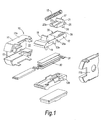
- a preferred form of latch mechanism is shown in the accompanying drawings and indicated by the reference numeral 10. It comprises a housing 11 formed by housing parts 11a and 11b. The housing receives a latch member 12 in such a fashion that the member 12 can reciprocate in a direction into and out of the housing 11 in a channel 13.
- the moveable member 12 is provided with an extension 14 which projects, in operation, out of the housing and forms the active part of the mechanism.
- the moveable member 12 is biased to the extended position with the portion 14 projecting out of the housing by means of a resilient member in the form of a coil spring 15, one end of which is received on a spring seat 16 provided on the moveable member 12 and the other end of which acts on the housing 11.
- the moveable member 12 acts as a freely reciprocating plunger under the bias of the spring 15.
- this control is such as to prevent the moveable member 12 being pushed into the housing against the action of the spring 15.
- This is achieved in a very simple fashion by means of a control member in the form of a pawl 17 which is best seen in Fig 1.
- the control member is arranged to partly project into a shaped recess 20 in the moveable member 12.
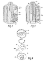
- the construction of the pawl 17 is important and from a comparison of the pawl 17 as shown in Figs 1, 2 and 3, it will be noted that it is provided with an angled arm 21 which is arranged to abut an angled internal surface 22 of the housing. Additionally, the pawl 17 is formed with legs 23 and 24 which extend away from a pivot 25 at an angle with respect to each other in order to form a bell crank lever.
- the leg 24 is shaped and of a length to extend into an elongate through hole 26 in the shaped recess 20 while the leg 23 extends substantially across the width of the recess 20 so that the end 23a of the leg 23 can be rotated into and out of engagement with the end wall 20a of the recess 20.
- the pawl 17 is biased to a position where the end 23a of the leg 23 is out of engagement with the end wall 20a of the recess 20 by virtue of the spring 15 acting on the angled arm 21.
- the member 12 With the mechanical assembly described thus far, and in the absence of any force being applied to the leg 24 of the pawl 17, the member 12 is still free to move in a direction into and out of the housing 11 under the action of the bias spring 15 in the presence of a force acting on the extension 14 of the member 12. However, if a force is applied to the leg 24 sufficient to overcome the spring force of the spring 15, the leg 23 is rotated about the pivot 22 resting on the angled surface 22 of the housing 11 to bring the end 23a of the leg 23 into engagement with the end wall 20a of the recess 20. When this occurs, the member 12 is blocked and cannot move in a direction into the housing 11 since the member 17 is trapped between the end 20a of the recess 20 and the sloping surface 22 of the housing.
- the force is applied to the leg 24 using a piezo ceramic actuator.
- the member 12 is a hollow member made up of two parts indicated by the sections 12a and 12b in Fig 1 and the piezo ceramic actuator indicated generally by the reference numeral 30 in Fig 1 is received within the hollow member 12.
- the electrical connections to the piezo ceramic actuator are not shown and the construction of the actuator is also merely exemplary of any one of a number of suitable constructions which might be used.
- the actuator is provided with an actuation member 31 which is moved into and out of engagement with the end of the leg 24.
- the portion 31 when the piezo electric actuator is energised, the portion 31 is moved to engage the leg 24 and as the member 12 tends to move into the housing, the leg 24 is rotated about the pivot 22 against the action of the spring 15 and thus the leg 23 is brought into blocking engagement with the end face 20a of the recess 20 in the moveable member 12.
- the portion 31 moves out of engagement with the end 24 and permits rotation of the bell crank lever under the action of the spring 15.
- the above construction has many advantages among which are the fact that the mechanism cannot be burst by simply applying a great deal of force on the portion 14 in order to force the member 12 into the housing 11 due to the fact that movement of the member 12 is being prevented by the pawl 17 and not by the piezo ceramic actuator itself which is merely acting as a control element. Additionally, the arrangement is mechanically self adjusting since the pawl 17 is not fixed to the internal surface 22 on the housing and so can slide down the incline in order to maintain contact with the member 12 even if wear occurs.
- the above construction has many uses, one being as a part of an electrically controllable clutch member in a mechanical drive.
- This use is exemplified in Fig 4 where the assembly 10 is fixed to a rotatable member 40 and selectively permits connection of the member 40 to a further rotatable member 41 by virtue of the extension 14 engaging in a slot 42 in order to transmit drive to the member 41 when the member 40 is rotated and vice versa.
- the power input means receives the necessary power to energise the electrically controlled actuator 30.
- Such a drive arrangement can conveniently be used in an electrically controlled door lock mechanism and it has low power consumption which means that it is suitable for battery powered operation.
Landscapes
- Engineering & Computer Science (AREA)
- Mechanical Engineering (AREA)
- Lock And Its Accessories (AREA)
- General Electrical Machinery Utilizing Piezoelectricity, Electrostriction Or Magnetostriction (AREA)
- Switch Cases, Indication, And Locking (AREA)
Claims (7)
- Verriegelungsmechanismus, der ein Gehäuse (11), einen Kolben (12), montiert in dem Gehäuse für eine Hin- und Herbewegung, und mit einem Bereich (14) besitzt, der, in einer Position des Kolbens, so angeordnet ist, um von dem Gehäuse vorzustehen, eine Klinke (17), die innerhalb des Gehäuses für eine Bewegung in einen Eingriff mit dem Kolben hinein und aus diesem heraus montiert ist, und Einrichtungen, um die Klinke zu bewegen, aufweist, wobei die Einrichtungen für die Bewegung der Klinke eine elektrisch gesteuerte Betätigungseinrichtung (30), die innerhalb des Kolbens angeordnet ist, aufweisen, und wobei die Klinke mit einem Teil (24) versehen ist, das in den Kolben hinein vorsteht und so angeordnet ist, um durch die Betätigungseinrichtung berührt zu werden, um eine Bewegung des Kolbens zu steuern, und
wobei dann, wenn die Betätigungseinrichtung (30) nicht in Kontakt mit dem Teil (24) steht, das in den Kolben vorsteht, der Kolben in der Lage ist, sich in dem Gehäuse hin- und herzubewegen. - Mechanismus nach Anspruch 1, wobei die Klinke in der Form eines Kipphebels vorliegt, wobei ein Arm davon einen Teil bildet, der in den Kolben vorsteht, und der andere Arm (23) so angeordnet ist, um gegen eine Oberfläche des Kolbens anzustoßen, um eine Bewegung des Kolbens zu verhindern.
- Mechanismus nach Anspruch 2, wobei die Klinke zu einer Position hin vorgespannt ist, wo der andere Arm (23) davor bewahrt wird, dass er gegen die Oberfläche des Kolbens anstößt.
- Mechanismus nach Anspruch 2, wobei die Betätigungseinrichtung in Kontakt mit der Klinke steht, wenn sich die Betätigungseinrichtung in einem nicht erregten Zustand befindet, und
wobei sich die Betätigungseinrichtung aus einem Kontakt mit der Klinke bewegt, wenn sich die Betätigungseinrichtung in einem erregten Zustand befindet. - Mechanismus nach Anspruch 2, 3 oder 4, wobei die Klinke in dem Gehäuse an einer schräg verlaufenden, inneren Fläche des Gehäuses angeordnet ist und frei ist, um sich sowohl zu drehen als auch linear auf der schräg verlaufenden, inneren Oberfläche zu bewegen.
- Mechanismus nach einem der vorhergehenden Ansprüche, wobei der Kolben zu einer verlängerten Position hin vorgespannt ist, wobei der Bereich (14) von dem Gehäuse vorsteht.
- Mechanismus nach einem der vorhergehenden Ansprüche, wobei die Betätigungseinrichtung in der Form einer piezokeramischen Vorrichtung vorliegt.
Applications Claiming Priority (3)
| Application Number | Priority Date | Filing Date | Title |
|---|---|---|---|
| GB0304671 | 2003-02-28 | ||
| GB0304671A GB2398826B (en) | 2003-02-28 | 2003-02-28 | Electrically controllable latch mechanism |
| PCT/GB2004/000729 WO2004077473A1 (en) | 2003-02-28 | 2004-02-25 | Electrically controllable latch mechanism |
Publications (2)
| Publication Number | Publication Date |
|---|---|
| EP1599888A1 EP1599888A1 (de) | 2005-11-30 |
| EP1599888B1 true EP1599888B1 (de) | 2006-08-02 |
Family
ID=9953896
Family Applications (1)
| Application Number | Title | Priority Date | Filing Date |
|---|---|---|---|
| EP04714366A Expired - Lifetime EP1599888B1 (de) | 2003-02-28 | 2004-02-25 | Elektrisch steuerbarer riegelmechanismus |
Country Status (7)
| Country | Link |
|---|---|
| US (1) | US7798538B2 (de) |
| EP (1) | EP1599888B1 (de) |
| JP (1) | JP2006519465A (de) |
| CN (1) | CN100409387C (de) |
| DE (1) | DE602004001763T2 (de) |
| GB (1) | GB2398826B (de) |
| WO (1) | WO2004077473A1 (de) |
Families Citing this family (13)
| Publication number | Priority date | Publication date | Assignee | Title |
|---|---|---|---|---|
| GB0427875D0 (en) * | 2004-12-20 | 2005-01-19 | Pbt Ip Ltd | Multiple purpose locking mechanism using active material switching |
| GB0512919D0 (en) * | 2005-06-24 | 2005-08-03 | Pbt Ip Ltd | Electronic securing device |
| GB2434398B (en) * | 2006-01-18 | 2010-09-08 | Pbt | Locking mechanism |
| GB0617827D0 (en) * | 2006-09-11 | 2006-10-18 | Pbt Ip Ltd | Electronic securing device |
| DE102007013480A1 (de) * | 2007-03-15 | 2008-09-18 | Euchner Gmbh + Co. Kg | Vorrichtung zum lösbaren Zuhalten eines verriegelten geschlossenen Zustandes einer Raumtrenneinrichtung |
| US7823993B2 (en) * | 2007-04-03 | 2010-11-02 | Carefusion 303, Inc. | Piezo actuated slide latching mechanism |
| GB2448527A (en) * | 2007-04-18 | 2008-10-22 | Pbt | Electronically controlled clutch arrangement for a locking mechanism comprising cams, actuator and sliding member |
| CN101383234B (zh) * | 2007-09-03 | 2013-04-03 | 美和锁株式会社 | 压电促动器 |
| FI121681B (fi) * | 2009-01-05 | 2011-02-28 | Megalock Oy | Lukon lisälaite |
| FI121679B (fi) * | 2009-03-23 | 2011-02-28 | Megalock Oy | Lukon lisälaite |
| FI20095694A7 (fi) | 2009-01-05 | 2010-07-06 | Megalock Oy | Langattomasti ohjattava sähkölukko |
| WO2010096034A1 (en) | 2009-02-20 | 2010-08-26 | Utc Fire & Security Corporation | Low energy clutch for electronic door lock |
| CN103038083B (zh) * | 2010-05-28 | 2016-11-16 | 凯毅德股份公司 | 用于机车的致动驱动器 |
Family Cites Families (25)
| Publication number | Priority date | Publication date | Assignee | Title |
|---|---|---|---|---|
| DE1138334B (de) * | 1962-02-07 | 1962-10-18 | Fuss Fritz Kg | Elektrischer Tueroeffner |
| US3799591A (en) * | 1972-05-09 | 1974-03-26 | Goal Lock Co | Latch lock |
| US4056276A (en) * | 1976-04-05 | 1977-11-01 | Jarvis Kenneth W | Door lock |
| GB2172753B (en) * | 1985-03-21 | 1989-01-05 | Delco Prod Overseas | Lockable electrically-operable actuator |
| US5386713A (en) * | 1991-03-07 | 1995-02-07 | Wilson; Bert | Remote control car deadbolt lock |
| US5278373A (en) * | 1991-10-18 | 1994-01-11 | Square D Company | Current limiting circuit breaker |
| DE4226304C2 (de) * | 1992-08-08 | 1995-01-05 | Kiekert Gmbh Co Kg | Elektromotorischer Stelltrieb für verstellbare Aggregate an einem Kraftfahrzeug |
| US5343179A (en) * | 1993-01-29 | 1994-08-30 | Eaton Corporation | Miniaturized solenoid operated trip device |
| FR2704090B1 (fr) * | 1993-04-16 | 1995-06-23 | Merlin Gerin | Declencheur auxiliaire pour disjoncteur. |
| CA2163320A1 (en) * | 1994-11-21 | 1996-05-22 | William C. Turnbull | Fused, spring latch |
| US5629662A (en) * | 1995-02-01 | 1997-05-13 | Siemens Energy & Automation, Inc. | Low energy memory metal actuated latch |
| US5649726A (en) * | 1996-05-21 | 1997-07-22 | General Motors Corporation | Vehicle closure latch |
| EP0851077B1 (de) * | 1996-12-30 | 2001-11-28 | NUOVA F.E.B. - Fabbrica Elettroapparecchiature Bologna S.r.l. | Verriegelungseinheit |
| CN2303371Y (zh) * | 1997-01-29 | 1999-01-06 | 陈华 | 用于供配电开关设备的机械软联锁装置 |
| US5936500A (en) * | 1997-06-18 | 1999-08-10 | Eaton Corporation | Bi-stable self-adjusting actuator mechanism |
| US5964487A (en) * | 1997-08-07 | 1999-10-12 | Shamblin; Rosco | Impact resistant security door auxiliary latch mechanism |
| JPH11224455A (ja) * | 1998-02-05 | 1999-08-17 | Nec Corp | ロック装置 |
| US6009732A (en) * | 1998-04-07 | 2000-01-04 | Detex Corporation | Panic exit device |
| WO2000036254A1 (en) * | 1998-12-16 | 2000-06-22 | Interlogix, Inc. | Slam bolt lock working in two way |
| GB9908927D0 (en) * | 1999-04-19 | 1999-06-16 | Pbt Limited | Electrically actuated mechanical release mechanism |
| US6211758B1 (en) * | 2000-01-11 | 2001-04-03 | General Electric Company | Circuit breaker accessory gap control mechanism |
| US6641183B2 (en) * | 2001-09-27 | 2003-11-04 | Jackson Corporation | Door latch device |
| ATE449227T1 (de) * | 2002-02-27 | 2009-12-15 | Emz Hanauer Gmbh & Co Kgaa | Einheit mit memory-metall-aktuator für türverriegelungen von haushaltsgeräten |
| KR20050004841A (ko) * | 2002-05-06 | 2005-01-12 | 나노머슬, 인크. | 형상기억합금으로 작동되는 재사용가능한 래치 |
| US20050046200A1 (en) * | 2003-08-28 | 2005-03-03 | Ford Global Technologies, Llc | Latch |
-
2003
- 2003-02-28 GB GB0304671A patent/GB2398826B/en not_active Expired - Fee Related
-
2004
- 2004-02-25 US US10/544,588 patent/US7798538B2/en not_active Expired - Fee Related
- 2004-02-25 CN CNB2004800052640A patent/CN100409387C/zh not_active Expired - Fee Related
- 2004-02-25 WO PCT/GB2004/000729 patent/WO2004077473A1/en not_active Ceased
- 2004-02-25 JP JP2006502319A patent/JP2006519465A/ja active Pending
- 2004-02-25 EP EP04714366A patent/EP1599888B1/de not_active Expired - Lifetime
- 2004-02-25 DE DE602004001763T patent/DE602004001763T2/de not_active Expired - Fee Related
Also Published As
| Publication number | Publication date |
|---|---|
| GB2398826A (en) | 2004-09-01 |
| CN1754238A (zh) | 2006-03-29 |
| WO2004077473A1 (en) | 2004-09-10 |
| EP1599888A1 (de) | 2005-11-30 |
| DE602004001763D1 (de) | 2006-09-14 |
| HK1065834A1 (en) | 2005-03-04 |
| US7798538B2 (en) | 2010-09-21 |
| GB2398826B (en) | 2006-02-01 |
| US20060214434A1 (en) | 2006-09-28 |
| CN100409387C (zh) | 2008-08-06 |
| JP2006519465A (ja) | 2006-08-24 |
| DE602004001763T2 (de) | 2007-08-02 |
| GB0304671D0 (en) | 2003-04-02 |
Similar Documents
| Publication | Publication Date | Title |
|---|---|---|
| EP1599888B1 (de) | Elektrisch steuerbarer riegelmechanismus | |
| US7827837B2 (en) | Electro-mechanical lock assembly | |
| JP4873595B2 (ja) | 電動複合ハンマ | |
| CN101770877B (zh) | 操作装置 | |
| CN112922461B (zh) | 一种锁止机构 | |
| CN100441824C (zh) | 电控门锁 | |
| US7724112B2 (en) | Safety switch | |
| CN110939340A (zh) | 一种门锁及其控制装置 | |
| WO2009109970A1 (en) | Lock mechanism blocking device | |
| JP4522291B2 (ja) | 安全スイッチ | |
| US20220098899A1 (en) | Electric door lock facility | |
| JPH07320590A (ja) | 自己復帰機能を有するスイッチ装置 | |
| EP0662553B1 (de) | Türdrückeranordnung | |
| JP7637716B2 (ja) | ソレノイドの駆動制御装置およびこれを備えた安全スイッチ | |
| WO1996042039A1 (en) | Electrically-operated latch | |
| JP2009024328A (ja) | ドアストライク装置 | |
| US7541555B2 (en) | Method and apparatus for dual mode switch | |
| US20220098900A1 (en) | Electric door lock device | |
| CN218676909U (zh) | 安全锁定装置 | |
| CN116658021B (zh) | 一种用于闭门器的连接装置及闭门器 | |
| WO2007049040A1 (en) | Low power lock mechanism | |
| RU2041519C1 (ru) | Фиксатор подвижного звена механизма | |
| JP3121177U (ja) | ドアの接点式給電装置 | |
| GB2084804A (en) | Rotary switch with electromagnetically retained resetting device | |
| JP2557687B2 (ja) | 係止装置における解除機構 |
Legal Events
| Date | Code | Title | Description |
|---|---|---|---|
| PUAI | Public reference made under article 153(3) epc to a published international application that has entered the european phase |
Free format text: ORIGINAL CODE: 0009012 |
|
| 17P | Request for examination filed |
Effective date: 20050729 |
|
| AK | Designated contracting states |
Kind code of ref document: A1 Designated state(s): DE FR GB IT |
|
| AX | Request for extension of the european patent |
Extension state: AL LT LV MK |
|
| GRAC | Information related to communication of intention to grant a patent modified |
Free format text: ORIGINAL CODE: EPIDOSCIGR1 |
|
| GRAP | Despatch of communication of intention to grant a patent |
Free format text: ORIGINAL CODE: EPIDOSNIGR1 |
|
| RBV | Designated contracting states (corrected) |
Designated state(s): DE FR GB IT |
|
| DAX | Request for extension of the european patent (deleted) | ||
| RBV | Designated contracting states (corrected) |
Designated state(s): DE FR GB IT |
|
| GRAS | Grant fee paid |
Free format text: ORIGINAL CODE: EPIDOSNIGR3 |
|
| GRAA | (expected) grant |
Free format text: ORIGINAL CODE: 0009210 |
|
| AK | Designated contracting states |
Kind code of ref document: B1 Designated state(s): DE FR GB IT |
|
| PG25 | Lapsed in a contracting state [announced via postgrant information from national office to epo] |
Ref country code: IT Free format text: LAPSE BECAUSE OF FAILURE TO SUBMIT A TRANSLATION OF THE DESCRIPTION OR TO PAY THE FEE WITHIN THE PRESCRIBED TIME-LIMIT;WARNING: LAPSES OF ITALIAN PATENTS WITH EFFECTIVE DATE BEFORE 2007 MAY HAVE OCCURRED AT ANY TIME BEFORE 2007. THE CORRECT EFFECTIVE DATE MAY BE DIFFERENT FROM THE ONE RECORDED. Effective date: 20060802 |
|
| REG | Reference to a national code |
Ref country code: GB Ref legal event code: FG4D |
|
| REF | Corresponds to: |
Ref document number: 602004001763 Country of ref document: DE Date of ref document: 20060914 Kind code of ref document: P |
|
| ET | Fr: translation filed | ||
| PLBE | No opposition filed within time limit |
Free format text: ORIGINAL CODE: 0009261 |
|
| STAA | Information on the status of an ep patent application or granted ep patent |
Free format text: STATUS: NO OPPOSITION FILED WITHIN TIME LIMIT |
|
| 26N | No opposition filed |
Effective date: 20070503 |
|
| PGFP | Annual fee paid to national office [announced via postgrant information from national office to epo] |
Ref country code: DE Payment date: 20090219 Year of fee payment: 6 |
|
| PGFP | Annual fee paid to national office [announced via postgrant information from national office to epo] |
Ref country code: IT Payment date: 20090212 Year of fee payment: 6 |
|
| PGFP | Annual fee paid to national office [announced via postgrant information from national office to epo] |
Ref country code: FR Payment date: 20090213 Year of fee payment: 6 |
|
| PGFP | Annual fee paid to national office [announced via postgrant information from national office to epo] |
Ref country code: GB Payment date: 20100202 Year of fee payment: 7 |
|
| REG | Reference to a national code |
Ref country code: FR Ref legal event code: ST Effective date: 20101029 |
|
| PG25 | Lapsed in a contracting state [announced via postgrant information from national office to epo] |
Ref country code: FR Free format text: LAPSE BECAUSE OF NON-PAYMENT OF DUE FEES Effective date: 20100301 |
|
| PG25 | Lapsed in a contracting state [announced via postgrant information from national office to epo] |
Ref country code: DE Free format text: LAPSE BECAUSE OF NON-PAYMENT OF DUE FEES Effective date: 20100901 |
|
| GBPC | Gb: european patent ceased through non-payment of renewal fee |
Effective date: 20110225 |
|
| PG25 | Lapsed in a contracting state [announced via postgrant information from national office to epo] |
Ref country code: GB Free format text: LAPSE BECAUSE OF NON-PAYMENT OF DUE FEES Effective date: 20110225 |
|
| PG25 | Lapsed in a contracting state [announced via postgrant information from national office to epo] |
Ref country code: IT Free format text: LAPSE BECAUSE OF NON-PAYMENT OF DUE FEES Effective date: 20100225 |