EP1599686B1 - Engrenage par friction destinee a un groupe auxiliaire separe d'un entrainement par courroie de groupe d'un moteur a combustion interne - Google Patents
Engrenage par friction destinee a un groupe auxiliaire separe d'un entrainement par courroie de groupe d'un moteur a combustion interne Download PDFInfo
- Publication number
- EP1599686B1 EP1599686B1 EP04706635A EP04706635A EP1599686B1 EP 1599686 B1 EP1599686 B1 EP 1599686B1 EP 04706635 A EP04706635 A EP 04706635A EP 04706635 A EP04706635 A EP 04706635A EP 1599686 B1 EP1599686 B1 EP 1599686B1
- Authority
- EP
- European Patent Office
- Prior art keywords
- contact surface
- friction
- friction wheel
- wheel
- drainage grooves
- Prior art date
- Legal status (The legal status is an assumption and is not a legal conclusion. Google has not performed a legal analysis and makes no representation as to the accuracy of the status listed.)
- Expired - Lifetime
Links
- 238000002485 combustion reaction Methods 0.000 description 7
- 229920001971 elastomer Polymers 0.000 description 4
- 239000002826 coolant Substances 0.000 description 3
- 239000012530 fluid Substances 0.000 description 3
- 239000007788 liquid Substances 0.000 description 3
- 239000005871 repellent Substances 0.000 description 3
- 230000002411 adverse Effects 0.000 description 2
- 239000000806 elastomer Substances 0.000 description 2
- 239000004033 plastic Substances 0.000 description 2
- 229920003023 plastic Polymers 0.000 description 2
- 239000005060 rubber Substances 0.000 description 2
- 239000007858 starting material Substances 0.000 description 2
- XLYOFNOQVPJJNP-UHFFFAOYSA-N water Substances O XLYOFNOQVPJJNP-UHFFFAOYSA-N 0.000 description 2
- 238000001816 cooling Methods 0.000 description 1
- 238000011161 development Methods 0.000 description 1
- 230000018109 developmental process Effects 0.000 description 1
- 230000000694 effects Effects 0.000 description 1
- 230000003993 interaction Effects 0.000 description 1
- 239000000463 material Substances 0.000 description 1
- 230000002940 repellent Effects 0.000 description 1
- 239000007921 spray Substances 0.000 description 1
Images


Classifications
-
- F—MECHANICAL ENGINEERING; LIGHTING; HEATING; WEAPONS; BLASTING
- F16—ENGINEERING ELEMENTS AND UNITS; GENERAL MEASURES FOR PRODUCING AND MAINTAINING EFFECTIVE FUNCTIONING OF MACHINES OR INSTALLATIONS; THERMAL INSULATION IN GENERAL
- F16H—GEARING
- F16H55/00—Elements with teeth or friction surfaces for conveying motion; Worms, pulleys or sheaves for gearing mechanisms
- F16H55/32—Friction members
- F16H55/34—Non-adjustable friction discs
-
- F—MECHANICAL ENGINEERING; LIGHTING; HEATING; WEAPONS; BLASTING
- F02—COMBUSTION ENGINES; HOT-GAS OR COMBUSTION-PRODUCT ENGINE PLANTS
- F02B—INTERNAL-COMBUSTION PISTON ENGINES; COMBUSTION ENGINES IN GENERAL
- F02B67/00—Engines characterised by the arrangement of auxiliary apparatus not being otherwise provided for, e.g. the apparatus having different functions; Driving auxiliary apparatus from engines, not otherwise provided for
- F02B67/04—Engines characterised by the arrangement of auxiliary apparatus not being otherwise provided for, e.g. the apparatus having different functions; Driving auxiliary apparatus from engines, not otherwise provided for of mechanically-driven auxiliary apparatus
- F02B67/06—Engines characterised by the arrangement of auxiliary apparatus not being otherwise provided for, e.g. the apparatus having different functions; Driving auxiliary apparatus from engines, not otherwise provided for of mechanically-driven auxiliary apparatus driven by means of chains, belts, or like endless members
-
- F—MECHANICAL ENGINEERING; LIGHTING; HEATING; WEAPONS; BLASTING
- F16—ENGINEERING ELEMENTS AND UNITS; GENERAL MEASURES FOR PRODUCING AND MAINTAINING EFFECTIVE FUNCTIONING OF MACHINES OR INSTALLATIONS; THERMAL INSULATION IN GENERAL
- F16H—GEARING
- F16H13/00—Gearing for conveying rotary motion with constant gear ratio by friction between rotary members
- F16H13/10—Means for influencing the pressure between the members
-
- F—MECHANICAL ENGINEERING; LIGHTING; HEATING; WEAPONS; BLASTING
- F16—ENGINEERING ELEMENTS AND UNITS; GENERAL MEASURES FOR PRODUCING AND MAINTAINING EFFECTIVE FUNCTIONING OF MACHINES OR INSTALLATIONS; THERMAL INSULATION IN GENERAL
- F16H—GEARING
- F16H7/00—Gearings for conveying rotary motion by endless flexible members
- F16H7/02—Gearings for conveying rotary motion by endless flexible members with belts; with V-belts
Definitions
- the invention relates to a friction wheel of a friction gear for an aggregates - belt drive an internal combustion engine separately arranged auxiliary unit, wherein the friction wheel is in frictional drive connection via a running surface on the one hand with the outside of the belt drive belt and on the other hand with a drive wheel of the auxiliary unit.
- the respective friction wheel cooperates with a substantially smooth outer side of the respective belt via a smooth running surface, whereby a fluid reaching between the contact surfaces of the friction partners adversely influences the drive connection by reducing the friction coefficient.
- the belt can be stimulated in particular by a slightly wobbling drive wheel to tilting movements, which lead to disadvantageous edge pressures in a friction wheel with a smooth, cylindrical tread.
- DE-A1-3934884 discloses the features of the preamble of claim 1.
- the invention has for its object to allow the running surface of a friction wheel such that the influence of a Reibbeiwert reducing liquid and the influence of edge stresses causing tilting movements of the belt are reduced about its longitudinal axis.
- the friction wheel is equipped on the outer circumference of a wheel body with a tire formed from liquid-repellent rubber, plastic or elastomer, the tread is divided by means of at least one drainage groove in tread areas, further wherein the tread in the edge regions or Shoulders of the tire is bevelled or rounded.
- the friction wheel running surface can be subdivided into separate running surface areas by at least one drainage groove extending in the circumferential direction of the friction wheel or by drainage grooves running transversely to the circumferential direction of the friction wheel.
- the friction wheel tread is divided into tread areas by means of a combination of at least one drainage groove extending in the circumferential direction with drainage grooves arranged transversely thereto.
- This also includes an embodiment with non-intersecting drainage grooves.
- a particularly effective liquid discharge is achieved in the case of a friction wheel tread, in which different tread areas are formed with a block profile and / or strip profile by means of differently oriented drainage grooves in an interconnected or crossing arrangement.
- the latter arrangement of drainage grooves achieves optimum fluid drainage with high frictional drive engagement, the drain additionally being provided over the tapered or rounded shoulders of the tread of the friction wheel tire is supported.
- a friction gear 3 is provided for a separate from the belt drive 1 on the internal combustion engine 2 auxiliary unit 4, which is preferably a coolant pump for the cooling circuit of the internal combustion engine 2.
- the friction gear 3 comprises a friction wheel 8, which frictionally cooperates with the outer side 7 of the belt 5 in a looping region of the belt 5 of a crankshaft side drive wheel 6 and a drive wheel 9 of the coolant pump 4 which can be frictionally driven by the friction wheel 8.
- the friction wheel 8 is controlled by means of a control device Controlled in particular at a cold start of the internal combustion engine 2 out of engagement with the pump-side drive wheel 9, as in Fig. 1 shown.
- the machine-side arranged control device 10 includes, for example, a controlled hub / rotatably driven, not visible eccentric, on a the friction wheel 8 leading arm 11 is pivotally mounted with an eye 12, wherein the friction wheel 8 is brought into and out of engagement with the drive wheel 9 via the controllable eccentric and the Schwenkarm11.
- the control device 10 is further equipped with a biased arranged, not apparent torsion spring which acts on the pivot arm 11 on the eye 12 so rotationally that the friction wheel 8 via its tread 13 at each adjustment relative to the drive wheel 9 equidistantly on the outside 7 of the belt 5 is guided pressed in the wrap of the drive wheel 6.
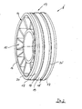
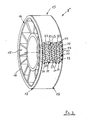
- the invention proposes that the respective, in the FIGS. 1 provided with 4 shown friction wheel 8,8 ', 8 ", 8'" on the outer circumference 14 of a wheel body 15 with a formed of liquid-repellent rubber, plastic or elastomer tire 16 whose tread 13 by means of at least one drainage groove 18, 18 '; 21, 22; 24, 25, 24 '; 28,29 is divided into tread areas, further wherein the tread 13 is chamfered or rounded in the edge regions or shoulders 17 of the tire 16.
- a simple embodiment of the invention according to Fig.2 is the tread 13 of the friction wheel 8 'by means of two axially spaced circumferentially - divided drainage grooves 18, 18' in a relatively wide central strip 19 and two relatively narrow side strips 20,20 'as respective annular tread areas.
- Figure 3 shows a friction wheel 8 "with a tread 13 shown only in sections, in which by means of differently directed drainage grooves 21 and 22 of each wave-shaped course in a crossing arrangement in the Running surface 13 is a profile of individually standing blocks 23 is formed. For example, rounded shoulders 17 close to the tread 13 with Kotzprofil 23 at.
- This block profile 23 with very narrow drainage grooves 21 and 22 is acoustically advantageous and has in the tread 13 on a high support share.
- FIG 4 a friction wheel 8 "', in which the tread 13 is subdivided into two relatively narrow center strips 26, 26' and two relatively wide side strips 27, 27 'in the middle region by means of differently shaped circumferential drainage grooves 24, 25 and 24'
- Running direction -arrow A -pulled transverse drainage grooves 28, 29 is formed in the center strips 26, 26 'a profile 30 with approximately square blocks 30' and in the side strips 27, 27 'a strip profile 31 with oblong rectangular blocks 31'
- the group of left drain grooves 28 is offset in the direction of running against the group of right drainage grooves 29.
- This configuration of the friction wheel running surface 13 is preferably used in the event of a high spray water attack.
Landscapes
- Engineering & Computer Science (AREA)
- General Engineering & Computer Science (AREA)
- Mechanical Engineering (AREA)
- Chemical & Material Sciences (AREA)
- Combustion & Propulsion (AREA)
- Tires In General (AREA)
Claims (8)
- Transmission à roue à friction pour une unité auxiliaire installée séparément d'une unité d'entraînement à courroie d'un moteur à combustion,
caractérisée en ce qu'- une roue à friction (8, 8', 8", 8"') est en contact d'entraînement par une surface de roulement (13) d'une part avec le côté extérieur (7) de la courroie (5) de l'entraînement à courroie et d'autre part, avec une roue d'entraînement (9) de l'unité auxiliaire (4) sous la forme d'une liaison d'entraînement par friction,- la périphérie extérieure (14) de la roue à friction (8, 8', 8", 8"') est munie d'un corps de roue (15) avec un bandage (16) repoussant le liquide, en caoutchouc, matière plastique ou élastomère, et dont- la surface de roulement (13) est subdivisée par une rainure de drainage (18, 18', 21, 22, 24, 25, 24', 28, 29) en zones de surface de circulation, et en outre- la surface de roulement (13) est inclinée ou arrondie dans les zones marginales ou les talons (17) du bandage (16). - Transmission à roue à friction selon la revendication 1,
caractérisée en ce que- la surface de roulement (13) de la roue à friction est subdivisée par au moins une rainure de drainage dans la direction périphérique de la roue à friction (8', 8", 8"'), des rainures de drainage (18, 18', 21, 24, 25, 24'), pour former des zones distinctes de surfaces de roulement. - Transmission à roue à friction selon la revendication 1,
caractérisée en ce que
la surface de roulement (13) de la roue à friction est subdivisée en zones de surface de roulement distinctes par des rainures de drainage (22, 28, 29) dirigées transversalement à la direction périphérique de la roue à friction (8", 8"'). - Transmission à roue à friction selon les revendications 2 et 3,
caractérisée en ce que- la surface de roulement (13) est subdivisée par au moins une rainure de drainage (18, 18', 21, 24, 25, 24') dans la direction périphérique combinée à des rainures de drainage (22, 28, 29) dirigées transversalement en des zones de surface de roulement. - Transmission à roue à friction selon la revendication 4,
caractérisée en ce qu'- des rainures de drainage (18, 18', 21, 22, 24, 25, 24', 28, 29), dirigées différemment, suivant une disposition reliée ou croisée, forment des zones de surface de roulement différentes avec un profil en forme de coin (23, 30) et/ou un profil en forme de bande (31). - Transmission à roue à friction selon la revendication 2,
caractérisée en ce que- la surface de roulement (13) de la roue à friction (8') est subdivisée par l'intermédiaire de deux rainures de drainage (18, 18'), périphériques, écartées axialement, en une bande centrale (19) relativement large et deux bandes latérales (20, 20') relativement étroites comme zones de surface de circulation annulaire, respectives, et- les bandes latérales (20, 20') se poursuivant chacune par un talon (17) incliné ou arrondi. - Transmission à roue à friction selon la revendication 5,
caractérisée en ce qu'- des rainures de drainage (21, 22) de direction différente avec un tracé respectif ondulé, et une disposition croisée dans la surface de roulement (13) de la roue à friction (8"), forment un profil en coin (23). - Transmission à roue à friction selon la revendication 5,
caractérisée en ce que- la surface de roulement (13) de la roue à friction (8"') présente dans sa zone médiane, deux bandes médianes (26, 26') relativement étroites grâce à des rainures de drainage périphériques (24, 25, 24') de largeur différente, et- en deux bandes latérales (27, 27') relativement larges, et par les rainures de drainage (28, 29) dirigées transversalement et en pointe par rapport à la direction de circulation de la roue à friction (8"'), on forme dans les bandes médianes (26, 26') un profil en forme de coin (30), et dans les bandes latérales (27, 27'), un profil en bande (31).
Applications Claiming Priority (3)
| Application Number | Priority Date | Filing Date | Title |
|---|---|---|---|
| DE2003109062 DE10309062A1 (de) | 2003-03-03 | 2003-03-03 | Reibrad eines Reibradgetriebes für ein von einem Aggregate-Riementrieb einer Brennkraftmaschine gesondert angeordnetes Nebenaggregat |
| DE10309062 | 2003-03-03 | ||
| PCT/EP2004/000849 WO2004079229A1 (fr) | 2003-03-03 | 2004-01-30 | Roue de friction d'un engrenage par friction destinee a un groupe auxiliaire separe d'un entrainement par courroie de groupe d'un moteur a combustion interne |
Publications (2)
| Publication Number | Publication Date |
|---|---|
| EP1599686A1 EP1599686A1 (fr) | 2005-11-30 |
| EP1599686B1 true EP1599686B1 (fr) | 2010-03-17 |
Family
ID=32864030
Family Applications (1)
| Application Number | Title | Priority Date | Filing Date |
|---|---|---|---|
| EP04706635A Expired - Lifetime EP1599686B1 (fr) | 2003-03-03 | 2004-01-30 | Engrenage par friction destinee a un groupe auxiliaire separe d'un entrainement par courroie de groupe d'un moteur a combustion interne |
Country Status (3)
| Country | Link |
|---|---|
| EP (1) | EP1599686B1 (fr) |
| DE (2) | DE10309062A1 (fr) |
| WO (1) | WO2004079229A1 (fr) |
Families Citing this family (5)
| Publication number | Priority date | Publication date | Assignee | Title |
|---|---|---|---|---|
| DE10346425A1 (de) | 2003-10-07 | 2005-05-19 | Bayerische Motoren Werke Ag | Reibradgetriebe für ein gesondertes Nebenaggregat einer mit riemengetriebenen Hilfsaggregaten ausgerüsteten Brennkraftmaschine |
| ITTO20030963A1 (it) | 2003-12-02 | 2005-06-03 | Dayco Europ Srl Con Unico Socio | Ruota di frizione perfezionata. |
| DE102005012006A1 (de) * | 2005-03-16 | 2006-09-28 | Bayerische Motoren Werke Ag | Brennkraftmaschine mit einem Riementrieb für Nebenaggregate |
| AT508908B1 (de) * | 2009-11-19 | 2011-05-15 | Faigle Kunststoffe Gmbh | Laufrad |
| FR2983905B1 (fr) * | 2011-12-09 | 2016-08-19 | Peugeot Citroen Automobiles Sa | Poulie d'entrainement de courroie d'accessoire de moteur a combustion interne, groupe motopropulseur et vehicule correspondants |
Family Cites Families (16)
| Publication number | Priority date | Publication date | Assignee | Title |
|---|---|---|---|---|
| DE492380C (de) * | 1928-05-16 | 1930-02-21 | Berlin Rixdorfer Gummiwaaren F | Gummilaufflaeche fuer Reibraedergetriebe |
| US2075865A (en) | 1936-03-02 | 1937-04-06 | Elwood C Phillips | Motor starter |
| GB633902A (en) * | 1946-05-21 | 1949-12-30 | Louis Granges | Driving means operating through friction |
| DE820230C (de) * | 1948-02-27 | 1951-11-08 | Andreas Breitbach | Reibrolle fuer Reibraedergetriebe |
| DE837946C (de) * | 1950-12-12 | 1952-05-02 | Continental Gummi Werke Ag | Reibrolle aus Gummi oder Gummiaustauschstoffen fuer Reibtriebe, insbesondere fuer Fahrradantriebsvorrichtungen |
| DE961318C (de) * | 1951-09-20 | 1957-04-04 | Continental Gummi Werke Ag | Reibraeder oder Reibrollen mit Belaegen aus Weichgummi |
| DE933840C (de) * | 1953-06-18 | 1955-10-06 | Continental Gummi Werke Ag | Hochbelastbares, elastisches Reibrad mit einem aus Gummi od. dgl. bestehenden Reibbelag |
| FR1172119A (fr) * | 1956-01-27 | 1959-02-05 | Vorwerk & Sohn | Organe rotatif applicable notamment comme poulie de contact pour ponceuses à ruban et comme bandage plein pour roues de véhicules |
| DE1810126U (de) * | 1960-02-24 | 1960-04-21 | Henschel Werke G M B H | Reibradantrieb fuer hilfsantriebe an fahrzeugmotoren. |
| FR1299074A (fr) * | 1961-06-08 | 1962-07-20 | G Ab | Variateur de vitesses à frictions multiples |
| DE3934884A1 (de) * | 1989-10-19 | 1991-04-25 | Bayerische Motoren Werke Ag | Endloses zugmittelgetriebe einer brennkraftmaschine |
| JPH1047436A (ja) * | 1996-08-08 | 1998-02-20 | Bando Chem Ind Ltd | 動力伝達用ベルト又はローラ |
| DE10236746A1 (de) | 2002-08-10 | 2004-02-19 | Bayerische Motoren Werke Ag | Brennkraftmaschine mit einer Antriebsanordnung für Aggregat-Module |
| DE10255074A1 (de) | 2002-11-26 | 2004-06-03 | Bayerische Motoren Werke Ag | Riementrieb für Hilfsaggregate einer Brennkraftmaschine |
| DE10255073A1 (de) | 2002-11-26 | 2004-06-03 | Bayerische Motoren Werke Ag | Mit einem Reibradgetriebe kombinierter Riementrieb zum Antrieb von Aggregaten einer Brennkraftmaschine |
| DE10255075A1 (de) | 2002-11-26 | 2004-06-03 | Bayerische Motoren Werke Ag | In einem Riementrieb für Aggregate einer Brennkraftmaschine vorgesehenes Reibradgetriebe für ein gesondertes Nebenaggregat |
-
2003
- 2003-03-03 DE DE2003109062 patent/DE10309062A1/de not_active Withdrawn
-
2004
- 2004-01-30 DE DE502004010905T patent/DE502004010905D1/de not_active Expired - Lifetime
- 2004-01-30 EP EP04706635A patent/EP1599686B1/fr not_active Expired - Lifetime
- 2004-01-30 WO PCT/EP2004/000849 patent/WO2004079229A1/fr not_active Ceased
Also Published As
| Publication number | Publication date |
|---|---|
| DE502004010905D1 (de) | 2010-04-29 |
| WO2004079229A1 (fr) | 2004-09-16 |
| DE10309062A1 (de) | 2004-09-16 |
| EP1599686A1 (fr) | 2005-11-30 |
Similar Documents
| Publication | Publication Date | Title |
|---|---|---|
| DE69502968T2 (de) | Rad mit veränderlichem Aussendurchmesser und Fahrzeug versehen damit | |
| EP1381533B1 (fr) | Systeme d'essuie-glace destine notamment a une automobile, et son procede de realisation | |
| DE3418222C2 (fr) | ||
| WO2008145456A1 (fr) | Palier de jambe de suspension et jambe de suspension | |
| DE10127224A1 (de) | Zahnrad | |
| DE3687876T2 (de) | Ausladungsventil fuer integrierte lenkeinrichtung. | |
| DE69407584T2 (de) | In ihrem wirksamen durchmesser veränderbare riemenscheibe mit stabilisierungsvorrichtung für den treibring | |
| EP0491130A1 (fr) | Pompe à eau pour circuit de refroidissement pour usage sur le carter d'un moteur à combustion interne | |
| EP1599686A1 (fr) | Roue de friction d'un engrenage par friction destinee a un groupe auxiliaire separe d'un entrainement par courroie de groupe d'un moteur a combustion interne | |
| WO2008055745A1 (fr) | Transmission par arbre à cames avec stabilisation géométrique du galet de roulement | |
| DE2710849C2 (de) | Hilfskraftlenkung für Fahrzeuge mit Rückführung | |
| WO2014135313A1 (fr) | Pompe haute pression pour système d'injection de carburant | |
| DE10255073A1 (de) | Mit einem Reibradgetriebe kombinierter Riementrieb zum Antrieb von Aggregaten einer Brennkraftmaschine | |
| WO2011018260A1 (fr) | Pompe haute pression | |
| EP3765758B1 (fr) | Engrenage à vis sans fin comprenant un palier pivotant comprenant un axe de pivotement défini | |
| EP1311760A1 (fr) | Machine hydraulique a pistons radiaux | |
| EP1329637B1 (fr) | Pompe régénérative | |
| EP0383167A1 (fr) | Moteur à pistons axiaux | |
| DE3334784A1 (de) | Kontinuierlich rotierend angetriebene schlagbohrmaschine | |
| DE19800787C1 (de) | Rad zur Verwendung in einem Riementrieb und Riementrieb | |
| DE112016004344T5 (de) | Tripode-gleichlaufuniversalgelenk | |
| DE202004010697U1 (de) | Ackerwalze | |
| WO2005017323A1 (fr) | Element support hydraulique | |
| DE3435872C2 (fr) | ||
| DE3216618C2 (fr) |
Legal Events
| Date | Code | Title | Description |
|---|---|---|---|
| PUAI | Public reference made under article 153(3) epc to a published international application that has entered the european phase |
Free format text: ORIGINAL CODE: 0009012 |
|
| 17P | Request for examination filed |
Effective date: 20050720 |
|
| AK | Designated contracting states |
Kind code of ref document: A1 Designated state(s): AT BE BG CH CY CZ DE DK EE ES FI FR GB GR HU IE IT LI LU MC NL PT RO SE SI SK TR |
|
| AX | Request for extension of the european patent |
Extension state: AL LT LV MK |
|
| DAX | Request for extension of the european patent (deleted) | ||
| RBV | Designated contracting states (corrected) |
Designated state(s): DE ES FR GB IT |
|
| 17Q | First examination report despatched |
Effective date: 20090608 |
|
| GRAP | Despatch of communication of intention to grant a patent |
Free format text: ORIGINAL CODE: EPIDOSNIGR1 |
|
| RTI1 | Title (correction) |
Free format text: FRICTION DRIVE FOR THE SEPARATE AUXILIARY GROUP OF A BELT DRIVE FOR AN INTERNAL COMBUSTION ENGINE |
|
| GRAS | Grant fee paid |
Free format text: ORIGINAL CODE: EPIDOSNIGR3 |
|
| GRAA | (expected) grant |
Free format text: ORIGINAL CODE: 0009210 |
|
| AK | Designated contracting states |
Kind code of ref document: B1 Designated state(s): DE ES FR GB IT |
|
| REG | Reference to a national code |
Ref country code: GB Ref legal event code: FG4D Free format text: NOT ENGLISH |
|
| REF | Corresponds to: |
Ref document number: 502004010905 Country of ref document: DE Date of ref document: 20100429 Kind code of ref document: P |
|
| PG25 | Lapsed in a contracting state [announced via postgrant information from national office to epo] |
Ref country code: ES Free format text: LAPSE BECAUSE OF FAILURE TO SUBMIT A TRANSLATION OF THE DESCRIPTION OR TO PAY THE FEE WITHIN THE PRESCRIBED TIME-LIMIT Effective date: 20100628 |
|
| PLBE | No opposition filed within time limit |
Free format text: ORIGINAL CODE: 0009261 |
|
| STAA | Information on the status of an ep patent application or granted ep patent |
Free format text: STATUS: NO OPPOSITION FILED WITHIN TIME LIMIT |
|
| 26N | No opposition filed |
Effective date: 20101220 |
|
| PG25 | Lapsed in a contracting state [announced via postgrant information from national office to epo] |
Ref country code: IT Free format text: LAPSE BECAUSE OF FAILURE TO SUBMIT A TRANSLATION OF THE DESCRIPTION OR TO PAY THE FEE WITHIN THE PRESCRIBED TIME-LIMIT Effective date: 20100317 |
|
| REG | Reference to a national code |
Ref country code: FR Ref legal event code: PLFP Year of fee payment: 13 |
|
| REG | Reference to a national code |
Ref country code: FR Ref legal event code: PLFP Year of fee payment: 14 |
|
| PGFP | Annual fee paid to national office [announced via postgrant information from national office to epo] |
Ref country code: DE Payment date: 20170121 Year of fee payment: 14 Ref country code: FR Payment date: 20170124 Year of fee payment: 14 |
|
| PGFP | Annual fee paid to national office [announced via postgrant information from national office to epo] |
Ref country code: GB Payment date: 20170125 Year of fee payment: 14 |
|
| REG | Reference to a national code |
Ref country code: DE Ref legal event code: R119 Ref document number: 502004010905 Country of ref document: DE |
|
| GBPC | Gb: european patent ceased through non-payment of renewal fee |
Effective date: 20180130 |
|
| PG25 | Lapsed in a contracting state [announced via postgrant information from national office to epo] |
Ref country code: DE Free format text: LAPSE BECAUSE OF NON-PAYMENT OF DUE FEES Effective date: 20180801 Ref country code: FR Free format text: LAPSE BECAUSE OF NON-PAYMENT OF DUE FEES Effective date: 20180131 |
|
| REG | Reference to a national code |
Ref country code: FR Ref legal event code: ST Effective date: 20180928 |
|
| PG25 | Lapsed in a contracting state [announced via postgrant information from national office to epo] |
Ref country code: GB Free format text: LAPSE BECAUSE OF NON-PAYMENT OF DUE FEES Effective date: 20180130 |