EP1599686B1 - Friction drive for the separate auxiliary group of a belt drive for an internal combustion engine - Google Patents
Friction drive for the separate auxiliary group of a belt drive for an internal combustion engine Download PDFInfo
- Publication number
- EP1599686B1 EP1599686B1 EP04706635A EP04706635A EP1599686B1 EP 1599686 B1 EP1599686 B1 EP 1599686B1 EP 04706635 A EP04706635 A EP 04706635A EP 04706635 A EP04706635 A EP 04706635A EP 1599686 B1 EP1599686 B1 EP 1599686B1
- Authority
- EP
- European Patent Office
- Prior art keywords
- contact surface
- friction
- friction wheel
- wheel
- drainage grooves
- Prior art date
- Legal status (The legal status is an assumption and is not a legal conclusion. Google has not performed a legal analysis and makes no representation as to the accuracy of the status listed.)
- Expired - Lifetime
Links
- 238000002485 combustion reaction Methods 0.000 description 7
- 229920001971 elastomer Polymers 0.000 description 4
- 239000002826 coolant Substances 0.000 description 3
- 239000012530 fluid Substances 0.000 description 3
- 239000007788 liquid Substances 0.000 description 3
- 239000005871 repellent Substances 0.000 description 3
- 230000002411 adverse Effects 0.000 description 2
- 239000000806 elastomer Substances 0.000 description 2
- 239000004033 plastic Substances 0.000 description 2
- 229920003023 plastic Polymers 0.000 description 2
- 239000005060 rubber Substances 0.000 description 2
- 239000007858 starting material Substances 0.000 description 2
- XLYOFNOQVPJJNP-UHFFFAOYSA-N water Substances O XLYOFNOQVPJJNP-UHFFFAOYSA-N 0.000 description 2
- 238000001816 cooling Methods 0.000 description 1
- 238000011161 development Methods 0.000 description 1
- 230000018109 developmental process Effects 0.000 description 1
- 230000000694 effects Effects 0.000 description 1
- 230000003993 interaction Effects 0.000 description 1
- 239000000463 material Substances 0.000 description 1
- 230000002940 repellent Effects 0.000 description 1
- 239000007921 spray Substances 0.000 description 1
Images


Classifications
-
- F—MECHANICAL ENGINEERING; LIGHTING; HEATING; WEAPONS; BLASTING
- F16—ENGINEERING ELEMENTS AND UNITS; GENERAL MEASURES FOR PRODUCING AND MAINTAINING EFFECTIVE FUNCTIONING OF MACHINES OR INSTALLATIONS; THERMAL INSULATION IN GENERAL
- F16H—GEARING
- F16H55/00—Elements with teeth or friction surfaces for conveying motion; Worms, pulleys or sheaves for gearing mechanisms
- F16H55/32—Friction members
- F16H55/34—Non-adjustable friction discs
-
- F—MECHANICAL ENGINEERING; LIGHTING; HEATING; WEAPONS; BLASTING
- F02—COMBUSTION ENGINES; HOT-GAS OR COMBUSTION-PRODUCT ENGINE PLANTS
- F02B—INTERNAL-COMBUSTION PISTON ENGINES; COMBUSTION ENGINES IN GENERAL
- F02B67/00—Engines characterised by the arrangement of auxiliary apparatus not being otherwise provided for, e.g. the apparatus having different functions; Driving auxiliary apparatus from engines, not otherwise provided for
- F02B67/04—Engines characterised by the arrangement of auxiliary apparatus not being otherwise provided for, e.g. the apparatus having different functions; Driving auxiliary apparatus from engines, not otherwise provided for of mechanically-driven auxiliary apparatus
- F02B67/06—Engines characterised by the arrangement of auxiliary apparatus not being otherwise provided for, e.g. the apparatus having different functions; Driving auxiliary apparatus from engines, not otherwise provided for of mechanically-driven auxiliary apparatus driven by means of chains, belts, or like endless members
-
- F—MECHANICAL ENGINEERING; LIGHTING; HEATING; WEAPONS; BLASTING
- F16—ENGINEERING ELEMENTS AND UNITS; GENERAL MEASURES FOR PRODUCING AND MAINTAINING EFFECTIVE FUNCTIONING OF MACHINES OR INSTALLATIONS; THERMAL INSULATION IN GENERAL
- F16H—GEARING
- F16H13/00—Gearing for conveying rotary motion with constant gear ratio by friction between rotary members
- F16H13/10—Means for influencing the pressure between the members
-
- F—MECHANICAL ENGINEERING; LIGHTING; HEATING; WEAPONS; BLASTING
- F16—ENGINEERING ELEMENTS AND UNITS; GENERAL MEASURES FOR PRODUCING AND MAINTAINING EFFECTIVE FUNCTIONING OF MACHINES OR INSTALLATIONS; THERMAL INSULATION IN GENERAL
- F16H—GEARING
- F16H7/00—Gearings for conveying rotary motion by endless flexible members
- F16H7/02—Gearings for conveying rotary motion by endless flexible members with belts; with V-belts
Definitions
- the invention relates to a friction wheel of a friction gear for an aggregates - belt drive an internal combustion engine separately arranged auxiliary unit, wherein the friction wheel is in frictional drive connection via a running surface on the one hand with the outside of the belt drive belt and on the other hand with a drive wheel of the auxiliary unit.
- the respective friction wheel cooperates with a substantially smooth outer side of the respective belt via a smooth running surface, whereby a fluid reaching between the contact surfaces of the friction partners adversely influences the drive connection by reducing the friction coefficient.
- the belt can be stimulated in particular by a slightly wobbling drive wheel to tilting movements, which lead to disadvantageous edge pressures in a friction wheel with a smooth, cylindrical tread.
- DE-A1-3934884 discloses the features of the preamble of claim 1.
- the invention has for its object to allow the running surface of a friction wheel such that the influence of a Reibbeiwert reducing liquid and the influence of edge stresses causing tilting movements of the belt are reduced about its longitudinal axis.
- the friction wheel is equipped on the outer circumference of a wheel body with a tire formed from liquid-repellent rubber, plastic or elastomer, the tread is divided by means of at least one drainage groove in tread areas, further wherein the tread in the edge regions or Shoulders of the tire is bevelled or rounded.
- the friction wheel running surface can be subdivided into separate running surface areas by at least one drainage groove extending in the circumferential direction of the friction wheel or by drainage grooves running transversely to the circumferential direction of the friction wheel.
- the friction wheel tread is divided into tread areas by means of a combination of at least one drainage groove extending in the circumferential direction with drainage grooves arranged transversely thereto.
- This also includes an embodiment with non-intersecting drainage grooves.
- a particularly effective liquid discharge is achieved in the case of a friction wheel tread, in which different tread areas are formed with a block profile and / or strip profile by means of differently oriented drainage grooves in an interconnected or crossing arrangement.
- the latter arrangement of drainage grooves achieves optimum fluid drainage with high frictional drive engagement, the drain additionally being provided over the tapered or rounded shoulders of the tread of the friction wheel tire is supported.
- a friction gear 3 is provided for a separate from the belt drive 1 on the internal combustion engine 2 auxiliary unit 4, which is preferably a coolant pump for the cooling circuit of the internal combustion engine 2.
- the friction gear 3 comprises a friction wheel 8, which frictionally cooperates with the outer side 7 of the belt 5 in a looping region of the belt 5 of a crankshaft side drive wheel 6 and a drive wheel 9 of the coolant pump 4 which can be frictionally driven by the friction wheel 8.
- the friction wheel 8 is controlled by means of a control device Controlled in particular at a cold start of the internal combustion engine 2 out of engagement with the pump-side drive wheel 9, as in Fig. 1 shown.
- the machine-side arranged control device 10 includes, for example, a controlled hub / rotatably driven, not visible eccentric, on a the friction wheel 8 leading arm 11 is pivotally mounted with an eye 12, wherein the friction wheel 8 is brought into and out of engagement with the drive wheel 9 via the controllable eccentric and the Schwenkarm11.
- the control device 10 is further equipped with a biased arranged, not apparent torsion spring which acts on the pivot arm 11 on the eye 12 so rotationally that the friction wheel 8 via its tread 13 at each adjustment relative to the drive wheel 9 equidistantly on the outside 7 of the belt 5 is guided pressed in the wrap of the drive wheel 6.
- the invention proposes that the respective, in the FIGS. 1 provided with 4 shown friction wheel 8,8 ', 8 ", 8'" on the outer circumference 14 of a wheel body 15 with a formed of liquid-repellent rubber, plastic or elastomer tire 16 whose tread 13 by means of at least one drainage groove 18, 18 '; 21, 22; 24, 25, 24 '; 28,29 is divided into tread areas, further wherein the tread 13 is chamfered or rounded in the edge regions or shoulders 17 of the tire 16.
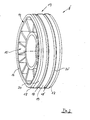
- a simple embodiment of the invention according to Fig.2 is the tread 13 of the friction wheel 8 'by means of two axially spaced circumferentially - divided drainage grooves 18, 18' in a relatively wide central strip 19 and two relatively narrow side strips 20,20 'as respective annular tread areas.
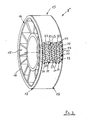
- Figure 3 shows a friction wheel 8 "with a tread 13 shown only in sections, in which by means of differently directed drainage grooves 21 and 22 of each wave-shaped course in a crossing arrangement in the Running surface 13 is a profile of individually standing blocks 23 is formed. For example, rounded shoulders 17 close to the tread 13 with Kotzprofil 23 at.
- This block profile 23 with very narrow drainage grooves 21 and 22 is acoustically advantageous and has in the tread 13 on a high support share.
- FIG 4 a friction wheel 8 "', in which the tread 13 is subdivided into two relatively narrow center strips 26, 26' and two relatively wide side strips 27, 27 'in the middle region by means of differently shaped circumferential drainage grooves 24, 25 and 24'
- Running direction -arrow A -pulled transverse drainage grooves 28, 29 is formed in the center strips 26, 26 'a profile 30 with approximately square blocks 30' and in the side strips 27, 27 'a strip profile 31 with oblong rectangular blocks 31'
- the group of left drain grooves 28 is offset in the direction of running against the group of right drainage grooves 29.
- This configuration of the friction wheel running surface 13 is preferably used in the event of a high spray water attack.
Landscapes
- Engineering & Computer Science (AREA)
- General Engineering & Computer Science (AREA)
- Mechanical Engineering (AREA)
- Chemical & Material Sciences (AREA)
- Combustion & Propulsion (AREA)
- Tires In General (AREA)
Description
Die Erfindung bezieht sich auf ein Reibrad eines Reibradgetriebes für von einem Aggregate - Riementrieb einer Brennkraftmaschine gesondert angeordnetes Nebenaggregat, wobei das Reibrad über eine Lauffläche einerseits mit der Außenseite des Riementrieb- Riemens und andererseits mit einem Antriebsrad des Nebenaggregates in reibschlüssiger Antriebsverbindung steht.The invention relates to a friction wheel of a friction gear for an aggregates - belt drive an internal combustion engine separately arranged auxiliary unit, wherein the friction wheel is in frictional drive connection via a running surface on the one hand with the outside of the belt drive belt and on the other hand with a drive wheel of the auxiliary unit.
Eine derartige Reibrad- Anordnung ist z.B. in der noch nicht veröffentlichten Patentanmeldung- P 102 55 074 gezeigt und beschrieben, wobei das Reibrad mittels eines exzentergesteuerten Schwingarmes in permanentem Eingriff mit dem Riemen und dem Antriebsrad gehalten ist. In den weiteren noch nicht veröffentlichten Patentanmeldungen P 102 55 075 und P 102 55 073, jeweils betreffend eine Steuerung des Reibrades zur Aufrechterhaltung oder zur Unterbrechung der Antriebsverbindung mit dem Antriebsrad des Nebenaggregates mittels eines auf unterschiedliche Weise gesteuerten Exzenters, sind ebenfalls die Außenseite des jeweiligen Riemens als auch die jeweiligen Laufflächen der gezeigten Reibräder glatt bzw. nicht profiliert dargestellt.Such Reibrad- arrangement is shown and described for example in the unpublished patent application P 102 55 074, wherein the friction wheel is held by means of an eccentric controlled swing arm in permanent engagement with the belt and the drive wheel. In the other unpublished patent applications P 102 55 075 and P 102 55 073, each relating to a control of the friction wheel for maintaining or interrupting the drive connection with the drive wheel of the auxiliary unit by means of a differently controlled eccentric, are also the outside of the respective belt as well as the respective running surfaces of the friction wheels shown smooth or not profiled.
Aus der
Derartige Profilierungen an Reibrad und Außenseite des Riemens sind in nachteiliger Weise aufwändig und somit kostenintensiv. Des weiteren sind solche Profilierungen aufgrund von Verschleiß wenig geeignet für Steuerungen des Reibrades in und außer Eingriff mit dem Antriebsrad, wobei das zu steuernde Reibrad zur Unterbrechung der Antriebsverbindung mit dem Antriebsrad in Längsrichtung des Riemens bewegt ist, wie in den vorgenannten Anmeldungen P 102 55 073 und P 102 55 075 angebeben. Eine Profilierung lediglich an einem der beiden Reibpartner ist zwar weniger aufwändig, jedoch mit einem starken Verschleiß verbunden.Such profiles on the friction wheel and the outside of the belt are disadvantageously complicated and thus costly. Furthermore, such profiles are due to wear little suitable for controls of the friction wheel in and out of engagement with the drive wheel, wherein the controlled friction wheel is moved to interrupt the drive connection with the drive wheel in the longitudinal direction of the belt, as in the aforementioned applications P 102 55 073 and P 102 55 075. Although a profiling on only one of the two friction partners is less complicated, but associated with a strong wear.
Bei den in den vorgenannten deutschen Anmeldungen gezeigten Reibrad-Anordnungen wirkt das jeweilige Reibrad über eine glatte Lauffläche mit einer im wesentlichen glatten Außenseite des jeweiligen Riemens zusammen, wobei eine zwischen die Kontaktflächen der Reibpartner gelangende Flüssigkeit durch Reduzierung des Reibbeiwertes die Antriebsverbindung ungünstig beeinflusst. Des weiteren kann der Riemen insbesondere durch ein geringfügig taumelndes Triebrad zu Kippbewegungen angeregt sein, die bei einem Reibrad mit glatter, zylindrischer Lauffläche zu nachteiligen Kantenpressungen führen.In the friction wheel arrangements shown in the aforementioned German applications, the respective friction wheel cooperates with a substantially smooth outer side of the respective belt via a smooth running surface, whereby a fluid reaching between the contact surfaces of the friction partners adversely influences the drive connection by reducing the friction coefficient. Furthermore, the belt can be stimulated in particular by a slightly wobbling drive wheel to tilting movements, which lead to disadvantageous edge pressures in a friction wheel with a smooth, cylindrical tread.
Diese Aufgabe ist mit dem Patentanspruch 1 dadurch gelöst, dass das Reibrad am Außenumfang eines Radkörpers mit einem aus flüssigkeitsabstoßenden Gummi, Kunststoff oder Elastomer gebildeten Reifen ausgerüstet ist, dessen Lauffläche mittels zumindest einer Drainagenut in Laufflächenbereiche unterteilt ist, wobei ferner die Lauffläche in den Randbereichen bzw. Schultern des Reifens abgeschrägt oder verrundet ist.This object is achieved by
Mit der Erfindung ist in vorteilhafter Weise ein Aquaplaning-Effekt im wesentlichen vermieden sowie ein materialschonendes Zusammenwirken von Riemen und Lauffläche des Reibrades erzielt.With the invention, an aquaplaning effect is avoided in an advantageous manner and achieved a material-friendly interaction of belt and tread of the friction wheel.
In Weiterbildungen der Erfindung kann die Reibrad - Lauffläche durch mindestens eine in Umfangsrichtung des Reibrades verlaufend angeordnete Drainagenut oder mittels quer zur Umfangsrichtung des Reibrades verlaufend angeordneten Drainagenuten jeweils in getrennte Laufflächenbereiche unterteilt sein. Für eine wirksame Ableitung von Wasser und / oder Öl aus dem Kontaktbereich von Reibrad und Riemen ist die Reibrad - Lauffläche mittels einer Kombination mindestens einer in Umfangsrichtung verlaufenden Drainagenut mit dazu quer gerichtet angeordneten Drainagenuten in Laufflächenbereiche unterteilt. Dies schließt auch eine Ausgestaltung mit sich nicht kreuzenden Drainagenuten ein. Eine besonders wirksame Flüssigkeits - Ableitung ist bei einer Reibrad - Lauffläche erreicht, bei der mittels unterschiedlich gerichteten Drainagenuten in einer miteinander verbundenen bzw. kreuzenden Anordnung unterschiedliche Laufflächenbereiche mit einem Klotzprofil und / oder Streifenprofil gebildet sind. In Verbindung mit der Wahl eines flüssigkeitabstoßenden Materials für die Reibrad - Lauffläche bzw. des Reifens ist mit der letztgenannten Anordnung von Drainagenuten eine optimale Flüssigkeitsableitung bei hoher reibschlüssige Antriebsverbindung erzielt, wobei die Ableitung zusätzlich über die abgeschrägten oder verrundeten Schultern des die Lauffläche aufweisenden Reifens des Reibrades unterstützt ist.In further developments of the invention, the friction wheel running surface can be subdivided into separate running surface areas by at least one drainage groove extending in the circumferential direction of the friction wheel or by drainage grooves running transversely to the circumferential direction of the friction wheel. For effective discharge of water and / or oil from the contact area of friction wheel and belt, the friction wheel tread is divided into tread areas by means of a combination of at least one drainage groove extending in the circumferential direction with drainage grooves arranged transversely thereto. This also includes an embodiment with non-intersecting drainage grooves. A particularly effective liquid discharge is achieved in the case of a friction wheel tread, in which different tread areas are formed with a block profile and / or strip profile by means of differently oriented drainage grooves in an interconnected or crossing arrangement. In conjunction with the choice of a fluid repellent material for the friction wheel tread, the latter arrangement of drainage grooves achieves optimum fluid drainage with high frictional drive engagement, the drain additionally being provided over the tapered or rounded shoulders of the tread of the friction wheel tire is supported.
Konkrete Ausgestaltungen der Erfindung sind in weiteren Ansprüchen angegeben.Concrete embodiments of the invention are specified in further claims.
Die Erfindung ist anhand von in der Zeichnung dargestellten Beispielen beschrieben. Es zeigt:
- Fig.1
- ein stirnseitig an einer abschnittsweise gezeigten Brennkraftmaschine mit einem Riementrieb zusammenwirkend angeordnetes Reibradgetriebe für ein gesondert angeordnetes Nebenaggregat, z.B. Kühlmittelpumpe,
- Fig. 2
- ein Reibrad des o.g. Reibradgetriebes mit einer Lauffläche, die durch mindestens eine in Umfangsrichtung des Reibrades verlaufend angeordnete Drainagenut in getrennte Laufflächenbereiche unterteilt ist,
- Fig.3
- ein Reibrad mit einer Lauffläche, die mittels unterschiedlich gerichteten Drainagenuten in einer kreuzenden Anordnung einen Lauftlächenbereich mit einem Klotzprofil aufweist, und
- Fig.4
- ein Reibrad mit einer Lauffläche, die mittels in Umfangsrichtung verlaufenden Drainagenuten in Kombination mit quer verlaufenden Drainagenuten in unterschiedliche Laufflächenbereiche mit einem Klotzprofil und einem Streifenprofil unterteilt ist.
- Fig.1
- an end face on a combustion engine shown in sections with a belt drive cooperatively arranged friction gear for a separately arranged auxiliary unit, eg coolant pump,
- Fig. 2
- a friction wheel of the above-mentioned friction gear with a running surface which is subdivided into separate running surface areas by at least one drainage groove arranged running in the circumferential direction of the friction wheel,
- Figure 3
- a friction wheel having a tread which has a tread region with a pad profile by means of differently directed drainage grooves in a crossing arrangement, and
- Figure 4
- a friction wheel having a tread which is divided by means of circumferentially extending drainage grooves in combination with transverse drainage grooves in different tread areas with a pad profile and a strip profile.
In einem Riementrieb 1 für nicht gezeigte Aggregate einer nur abschnittsweise dargestellten Brennkraftmaschine 2 ist ein Reibradgetriebe 3 vorgesehen für ein vom Riementrieb 1 gesondert an der Brennkraftmaschine 2 angeordnetes Nebenaggregat 4, das vorzugsweise eine Kühlmittelpumpe für den Kühlkreislauf der Brennkraftmaschine 2 ist.In a
Das Reibradgetriebe 3 umfasst ein in einem Umschlingungsbereich des Riemens 5 eines kurbelwellenseitigen Triebrades 6 der Brennkraftmaschine 2 mit der Außenseite 7 des Riemens 5 reibschlüssig zusammenwirkendes Reibrad 8 und ein mit dem Reibrad 8 reibschlüssig antreibbares Antriebsrad 9 der Kühlmittelpumpe 4. Das Reibrad 8 ist mittels einer Steuereinrichtung 10 insbesondere bei einem Kaltstart der Brennkraftmaschine 2 außer Eingriff mit dem pumpenseitigen Antriebsrad 9 gesteuert, wie in
Die maschinenseitig angeordnete Steuereinrichtung 10 umfasst z.B. einen gesteuert hub-/drehbeweglich antreibbaren, nicht ersichtlichen Exzenter, auf dem ein das Reibrad 8 führender Schwenkarm 11 mit einem Auge 12 schwenkbeweglich gelagert ist, wobei über den steuerbaren Exzenter und dem Schwenkarm11 das Reibrad 8 in und außer Eingriff mit dem Antriebsrad 9 gebracht ist. Die Steuereinrichtung 10 ist ferner mit einer vorgespannt angeordneten, nicht ersichtlichen Drehfeder ausgerüstet, die über das Auge 12 auf den Schwenkarm 11 derart drehend einwirkt, dass das Reibrad 8 über seine Lauffläche 13 bei jeder Verstellung relativ zum Antriebsrad 9 äquidistant auf der Außenseite 7 des Riemens 5 im Umschlingungsbereich des Triebrades 6 angedrückt geführt ist.The machine-side arranged
Um den nachteiligen Einfluss einer den Reibbeiwert reduzierenden Flüssigkeit zwischen den Kontaktflächen des Reibrades 8 und des Riemens 5 zu vermindern sowie am Reibrad Kantenpressungen verursachende Kippbewegungen des Riemens um die Riemenlängsachse insbesondere durch ein kurbelwellenseitig angetriebenes, taumelndes Triebrad, wird erfindungsgemäß vorgeschlagen, dass das jeweilige, in den
Gemäß einer einfachen Ausgestaltung der Erfindung nach
Schließlich zeigt
Mit der Erfindung ist ein verbesserter Kraftschluss zwischen dem jeweiligen Reibrad und dem Riemen des Aggregate - Riementriebes erzielt.With the invention, an improved frictional connection between the respective friction wheel and the belt of the aggregate belt drive is achieved.
Claims (8)
- A friction drive for an auxiliary unit arranged separately from a unit belt drive of an internal combustion engine, characterised in that- a friction wheel (8, 8', 8", 8"') is in frictional drive connection via a contact surface (13), on the one hand, with the outside (7) of the belt drive belt (5) and, on the other hand, with a drive wheel (9) of the auxiliary unit (4),- in that the friction wheel (8, 8', 8", 8"') is equipped at the outer periphery (14) of a wheel body (15) with a tyre (16) formed from liquid-repellent rubber, plastics material or elastomer, of which- the contact surface (13) is divided by means of at least one drainage groove (18, 18'; 21, 22; 24, 25, 24', 28, 29) into contact surface regions, wherein, furthermore,- the contact surface (13) is bevelled or rounded in the edge regions or shoulders (17) of the tyre (16).
- A friction drive according to claim 1, characterised in that- the friction wheel contact surface (13) is divided by at least one drainage groove (18, 18'; 21; 24, 25, 24') arranged running in the peripheral direction of the friction wheel (8', 8", 8"') into separate contact surface regions.
- A friction drive according to claim 1, characterised in that- the friction wheel contact surface (13) is divided by means of drainage grooves (22; 28, 29) arranged running transversely to the peripheral direction of the friction wheel (8", 8"') into separate contact surface regions.
- A friction drive according to claim 2 and 3, characterised in that- the contact surface (13) is divided by means of at least one drainage groove (18, 18'; 21; 24, 25, 24') extending in the peripheral direction in combination with drainage grooves (22; 28, 29) arranged directly transversely into separate contact surface regions.
- A friction drive according to claim 4, characterised in that- different contact surface regions with a block profile (23, 30) and/or a strip profile (31) are formed by means of differently directed drainage grooves (18, 18'; 21, 22; 24, 25, 24'; 28, 29) in an arrangement connected to or crossing one another.
- A friction drive according to claim 2, characterised in that- the contact surface (13) of the friction wheel (8') is divided by means of two axially spaced apart peripheral drainage grooves (18, 18') into a relatively broad central strip (19) and two relatively narrow side strips (20, 20') as respective annular contact surface regions, wherein- a bevelled or rounded shoulder (17) adjoins the side strips (20, 20') in each case.
- A friction drive according to claim 5, characterised in that- a block profile (23) is formed by means of differently directed drainage grooves (21, 22) with a respective wave-like course in a crossing arrangement in the contact surface (13) of the friction wheel (8").
- A friction drive according to claim 5, characterised in that- the contact surface (13) of the friction wheel (8"') is divided in the central region by means of peripheral drainage grooves (24, 25, 24') of different width into two relatively narrow central strips (26, 26') and- into two relatively wide side strips (27, 27'), wherein- a block profile (30) is formed by means of transverse drainage grooves (28, 29) with an arrow arrangement in the running direction of the friction wheel (8"') in the centre strips (26, 26') and a strip profile (31) is formed in the side strips (27, 27').
Applications Claiming Priority (3)
| Application Number | Priority Date | Filing Date | Title |
|---|---|---|---|
| DE2003109062 DE10309062A1 (en) | 2003-03-03 | 2003-03-03 | Friction wheel of a friction wheel transmission for an auxiliary unit arranged separately from an aggregate belt drive of an internal combustion engine |
| DE10309062 | 2003-03-03 | ||
| PCT/EP2004/000849 WO2004079229A1 (en) | 2003-03-03 | 2004-01-30 | Friction wheel for a friction drive for the separate auxiliary group of a belt drive for an internal combustion engine |
Publications (2)
| Publication Number | Publication Date |
|---|---|
| EP1599686A1 EP1599686A1 (en) | 2005-11-30 |
| EP1599686B1 true EP1599686B1 (en) | 2010-03-17 |
Family
ID=32864030
Family Applications (1)
| Application Number | Title | Priority Date | Filing Date |
|---|---|---|---|
| EP04706635A Expired - Lifetime EP1599686B1 (en) | 2003-03-03 | 2004-01-30 | Friction drive for the separate auxiliary group of a belt drive for an internal combustion engine |
Country Status (3)
| Country | Link |
|---|---|
| EP (1) | EP1599686B1 (en) |
| DE (2) | DE10309062A1 (en) |
| WO (1) | WO2004079229A1 (en) |
Families Citing this family (5)
| Publication number | Priority date | Publication date | Assignee | Title |
|---|---|---|---|---|
| DE10346425A1 (en) | 2003-10-07 | 2005-05-19 | Bayerische Motoren Werke Ag | Friction gear for a separate accessory of equipped with belt-driven auxiliary equipment internal combustion engine |
| ITTO20030963A1 (en) | 2003-12-02 | 2005-06-03 | Dayco Europ Srl Con Unico Socio | PERFECT CLUTCH WHEEL. |
| DE102005012006A1 (en) * | 2005-03-16 | 2006-09-28 | Bayerische Motoren Werke Ag | Internal combustion engine with a belt drive for ancillaries |
| AT508908B1 (en) * | 2009-11-19 | 2011-05-15 | Faigle Kunststoffe Gmbh | WHEEL |
| FR2983905B1 (en) * | 2011-12-09 | 2016-08-19 | Peugeot Citroen Automobiles Sa | INTERNAL COMBUSTION ENGINE ACCESSORY BELT DRIVE PULLEY, POWER UNIT AND CORRESPONDING VEHICLE |
Family Cites Families (16)
| Publication number | Priority date | Publication date | Assignee | Title |
|---|---|---|---|---|
| DE492380C (en) * | 1928-05-16 | 1930-02-21 | Berlin Rixdorfer Gummiwaaren F | Rubber tread for friction gear |
| US2075865A (en) | 1936-03-02 | 1937-04-06 | Elwood C Phillips | Motor starter |
| GB633902A (en) * | 1946-05-21 | 1949-12-30 | Louis Granges | Driving means operating through friction |
| DE820230C (en) * | 1948-02-27 | 1951-11-08 | Andreas Breitbach | Friction roller for friction gear transmission |
| DE837946C (en) * | 1950-12-12 | 1952-05-02 | Continental Gummi Werke Ag | Friction roller made of rubber or rubber substitutes for friction drives, especially for bicycle drive devices |
| DE961318C (en) * | 1951-09-20 | 1957-04-04 | Continental Gummi Werke Ag | Friction wheels or friction rollers with soft rubber pads |
| DE933840C (en) * | 1953-06-18 | 1955-10-06 | Continental Gummi Werke Ag | Heavy-duty, elastic friction wheel with a friction lining made of rubber or the like |
| FR1172119A (en) * | 1956-01-27 | 1959-02-05 | Vorwerk & Sohn | Rotary member applicable in particular as a contact pulley for belt sanders and as a solid tire for vehicle wheels |
| DE1810126U (en) * | 1960-02-24 | 1960-04-21 | Henschel Werke G M B H | FRICTION WHEEL DRIVE FOR AUXILIARY DRIVES ON VEHICLE ENGINES. |
| FR1299074A (en) * | 1961-06-08 | 1962-07-20 | G Ab | Multiple friction variable speed drive |
| DE3934884A1 (en) * | 1989-10-19 | 1991-04-25 | Bayerische Motoren Werke Ag | Auxiliary drive mechanism for IC engine - incorporates tension wheel pressing against belt and driving shaft |
| JPH1047436A (en) * | 1996-08-08 | 1998-02-20 | Bando Chem Ind Ltd | Power transmission belt or roller |
| DE10236746A1 (en) | 2002-08-10 | 2004-02-19 | Bayerische Motoren Werke Ag | Internal combustion engine with a drive arrangement for unit modules |
| DE10255075A1 (en) | 2002-11-26 | 2004-06-03 | Bayerische Motoren Werke Ag | In a belt drive for units of an internal combustion engine provided friction gear for a separate auxiliary unit |
| DE10255073A1 (en) | 2002-11-26 | 2004-06-03 | Bayerische Motoren Werke Ag | Belt drive combined with a friction gear for driving units of an internal combustion engine |
| DE10255074A1 (en) | 2002-11-26 | 2004-06-03 | Bayerische Motoren Werke Ag | Belt drive for auxiliary units of an internal combustion engine |
-
2003
- 2003-03-03 DE DE2003109062 patent/DE10309062A1/en not_active Withdrawn
-
2004
- 2004-01-30 EP EP04706635A patent/EP1599686B1/en not_active Expired - Lifetime
- 2004-01-30 WO PCT/EP2004/000849 patent/WO2004079229A1/en not_active Ceased
- 2004-01-30 DE DE502004010905T patent/DE502004010905D1/en not_active Expired - Lifetime
Also Published As
| Publication number | Publication date |
|---|---|
| WO2004079229A1 (en) | 2004-09-16 |
| EP1599686A1 (en) | 2005-11-30 |
| DE10309062A1 (en) | 2004-09-16 |
| DE502004010905D1 (en) | 2010-04-29 |
Similar Documents
| Publication | Publication Date | Title |
|---|---|---|
| DE69502968T2 (en) | Provide wheel with variable outside diameter and vehicle | |
| DE3418222C2 (en) | ||
| WO2002076797A1 (en) | Windshield wiper, especially for motor vehicles and method for the production of said windshield wiper | |
| WO2008145456A1 (en) | Shock strut bearing and shock strut | |
| DE10127224A1 (en) | Toothed wheel, especially for a worm gear mechanism, comprising a metal disc with a central opening for a shaft and a ring shaped plastic element | |
| DE3687876T2 (en) | DISCHARGE VALVE FOR INTEGRATED STEERING DEVICE. | |
| EP1599686B1 (en) | Friction drive for the separate auxiliary group of a belt drive for an internal combustion engine | |
| EP0491130B1 (en) | Cooling water pump for use on the housing of an internal combustion engine | |
| DE69407584T2 (en) | IN ITS EFFECTIVE DIAMETER CHANGEABLE PULLEY WITH STABILIZING DEVICE FOR THE DRIVE RING | |
| WO2008055745A1 (en) | Camshaft drive with geometric cam roller stabilization | |
| DE2710849C2 (en) | Power steering for vehicles with feedback | |
| WO2014135313A1 (en) | High-pressure pump for a fuel injection system | |
| DE10255073A1 (en) | Belt drive combined with a friction gear for driving units of an internal combustion engine | |
| WO2011018260A1 (en) | High-pressure pump | |
| EP1810904B1 (en) | Pump device | |
| DE10360290A1 (en) | Plastic-coated roller, in particular tensioning roller for a belt drive | |
| EP0928908B1 (en) | Wheel for use in a belt drive and belt drive | |
| EP3765758B1 (en) | Helical gear transmission comprising a pivot bearing with a defined pivot axis | |
| EP1311760A1 (en) | Hydraulic radial piston engine | |
| EP1329637B1 (en) | Regenerative pump | |
| DE112016004344T5 (en) | TRIPODE-TRACKING UNIVERSAL JOINT | |
| DE202004010697U1 (en) | Ackerwalze | |
| DE3435872C2 (en) | ||
| DE3216618C2 (en) | ||
| DE20212758U1 (en) | Pre-assembled cassette seal with integrated running surface |
Legal Events
| Date | Code | Title | Description |
|---|---|---|---|
| PUAI | Public reference made under article 153(3) epc to a published international application that has entered the european phase |
Free format text: ORIGINAL CODE: 0009012 |
|
| 17P | Request for examination filed |
Effective date: 20050720 |
|
| AK | Designated contracting states |
Kind code of ref document: A1 Designated state(s): AT BE BG CH CY CZ DE DK EE ES FI FR GB GR HU IE IT LI LU MC NL PT RO SE SI SK TR |
|
| AX | Request for extension of the european patent |
Extension state: AL LT LV MK |
|
| DAX | Request for extension of the european patent (deleted) | ||
| RBV | Designated contracting states (corrected) |
Designated state(s): DE ES FR GB IT |
|
| 17Q | First examination report despatched |
Effective date: 20090608 |
|
| GRAP | Despatch of communication of intention to grant a patent |
Free format text: ORIGINAL CODE: EPIDOSNIGR1 |
|
| RTI1 | Title (correction) |
Free format text: FRICTION DRIVE FOR THE SEPARATE AUXILIARY GROUP OF A BELT DRIVE FOR AN INTERNAL COMBUSTION ENGINE |
|
| GRAS | Grant fee paid |
Free format text: ORIGINAL CODE: EPIDOSNIGR3 |
|
| GRAA | (expected) grant |
Free format text: ORIGINAL CODE: 0009210 |
|
| AK | Designated contracting states |
Kind code of ref document: B1 Designated state(s): DE ES FR GB IT |
|
| REG | Reference to a national code |
Ref country code: GB Ref legal event code: FG4D Free format text: NOT ENGLISH |
|
| REF | Corresponds to: |
Ref document number: 502004010905 Country of ref document: DE Date of ref document: 20100429 Kind code of ref document: P |
|
| PG25 | Lapsed in a contracting state [announced via postgrant information from national office to epo] |
Ref country code: ES Free format text: LAPSE BECAUSE OF FAILURE TO SUBMIT A TRANSLATION OF THE DESCRIPTION OR TO PAY THE FEE WITHIN THE PRESCRIBED TIME-LIMIT Effective date: 20100628 |
|
| PLBE | No opposition filed within time limit |
Free format text: ORIGINAL CODE: 0009261 |
|
| STAA | Information on the status of an ep patent application or granted ep patent |
Free format text: STATUS: NO OPPOSITION FILED WITHIN TIME LIMIT |
|
| 26N | No opposition filed |
Effective date: 20101220 |
|
| PG25 | Lapsed in a contracting state [announced via postgrant information from national office to epo] |
Ref country code: IT Free format text: LAPSE BECAUSE OF FAILURE TO SUBMIT A TRANSLATION OF THE DESCRIPTION OR TO PAY THE FEE WITHIN THE PRESCRIBED TIME-LIMIT Effective date: 20100317 |
|
| REG | Reference to a national code |
Ref country code: FR Ref legal event code: PLFP Year of fee payment: 13 |
|
| REG | Reference to a national code |
Ref country code: FR Ref legal event code: PLFP Year of fee payment: 14 |
|
| PGFP | Annual fee paid to national office [announced via postgrant information from national office to epo] |
Ref country code: DE Payment date: 20170121 Year of fee payment: 14 Ref country code: FR Payment date: 20170124 Year of fee payment: 14 |
|
| PGFP | Annual fee paid to national office [announced via postgrant information from national office to epo] |
Ref country code: GB Payment date: 20170125 Year of fee payment: 14 |
|
| REG | Reference to a national code |
Ref country code: DE Ref legal event code: R119 Ref document number: 502004010905 Country of ref document: DE |
|
| GBPC | Gb: european patent ceased through non-payment of renewal fee |
Effective date: 20180130 |
|
| PG25 | Lapsed in a contracting state [announced via postgrant information from national office to epo] |
Ref country code: DE Free format text: LAPSE BECAUSE OF NON-PAYMENT OF DUE FEES Effective date: 20180801 Ref country code: FR Free format text: LAPSE BECAUSE OF NON-PAYMENT OF DUE FEES Effective date: 20180131 |
|
| REG | Reference to a national code |
Ref country code: FR Ref legal event code: ST Effective date: 20180928 |
|
| PG25 | Lapsed in a contracting state [announced via postgrant information from national office to epo] |
Ref country code: GB Free format text: LAPSE BECAUSE OF NON-PAYMENT OF DUE FEES Effective date: 20180130 |