EP1599685B1 - Engrenage a roue de friction destine a un groupe auxiliaire separe d'un entrainement a courroie de groupe d'un moteur a combustion interne - Google Patents
Engrenage a roue de friction destine a un groupe auxiliaire separe d'un entrainement a courroie de groupe d'un moteur a combustion interne Download PDFInfo
- Publication number
- EP1599685B1 EP1599685B1 EP04706667A EP04706667A EP1599685B1 EP 1599685 B1 EP1599685 B1 EP 1599685B1 EP 04706667 A EP04706667 A EP 04706667A EP 04706667 A EP04706667 A EP 04706667A EP 1599685 B1 EP1599685 B1 EP 1599685B1
- Authority
- EP
- European Patent Office
- Prior art keywords
- friction
- eccentric
- drive
- wheel
- gear
- Prior art date
- Legal status (The legal status is an assumption and is not a legal conclusion. Google has not performed a legal analysis and makes no representation as to the accuracy of the status listed.)
- Expired - Lifetime
Links
- 238000002485 combustion reaction Methods 0.000 title claims description 11
- 239000002826 coolant Substances 0.000 claims description 14
- 230000000284 resting effect Effects 0.000 claims description 2
- 230000005540 biological transmission Effects 0.000 description 4
- 238000010276 construction Methods 0.000 description 2
- 238000009434 installation Methods 0.000 description 1
- 238000000034 method Methods 0.000 description 1
Images




Classifications
-
- F—MECHANICAL ENGINEERING; LIGHTING; HEATING; WEAPONS; BLASTING
- F02—COMBUSTION ENGINES; HOT-GAS OR COMBUSTION-PRODUCT ENGINE PLANTS
- F02B—INTERNAL-COMBUSTION PISTON ENGINES; COMBUSTION ENGINES IN GENERAL
- F02B67/00—Engines characterised by the arrangement of auxiliary apparatus not being otherwise provided for, e.g. the apparatus having different functions; Driving auxiliary apparatus from engines, not otherwise provided for
- F02B67/04—Engines characterised by the arrangement of auxiliary apparatus not being otherwise provided for, e.g. the apparatus having different functions; Driving auxiliary apparatus from engines, not otherwise provided for of mechanically-driven auxiliary apparatus
- F02B67/06—Engines characterised by the arrangement of auxiliary apparatus not being otherwise provided for, e.g. the apparatus having different functions; Driving auxiliary apparatus from engines, not otherwise provided for of mechanically-driven auxiliary apparatus driven by means of chains, belts, or like endless members
-
- F—MECHANICAL ENGINEERING; LIGHTING; HEATING; WEAPONS; BLASTING
- F01—MACHINES OR ENGINES IN GENERAL; ENGINE PLANTS IN GENERAL; STEAM ENGINES
- F01P—COOLING OF MACHINES OR ENGINES IN GENERAL; COOLING OF INTERNAL-COMBUSTION ENGINES
- F01P5/00—Pumping cooling-air or liquid coolants
- F01P5/10—Pumping liquid coolant; Arrangements of coolant pumps
- F01P5/12—Pump-driving arrangements
-
- F—MECHANICAL ENGINEERING; LIGHTING; HEATING; WEAPONS; BLASTING
- F01—MACHINES OR ENGINES IN GENERAL; ENGINE PLANTS IN GENERAL; STEAM ENGINES
- F01P—COOLING OF MACHINES OR ENGINES IN GENERAL; COOLING OF INTERNAL-COMBUSTION ENGINES
- F01P5/00—Pumping cooling-air or liquid coolants
- F01P5/14—Safety means against, or active at, failure of coolant-pumps drives, e.g. shutting engine down; Means for indicating functioning of coolant pumps
-
- F—MECHANICAL ENGINEERING; LIGHTING; HEATING; WEAPONS; BLASTING
- F02—COMBUSTION ENGINES; HOT-GAS OR COMBUSTION-PRODUCT ENGINE PLANTS
- F02B—INTERNAL-COMBUSTION PISTON ENGINES; COMBUSTION ENGINES IN GENERAL
- F02B63/00—Adaptations of engines for driving pumps, hand-held tools or electric generators; Portable combinations of engines with engine-driven devices
-
- F—MECHANICAL ENGINEERING; LIGHTING; HEATING; WEAPONS; BLASTING
- F16—ENGINEERING ELEMENTS AND UNITS; GENERAL MEASURES FOR PRODUCING AND MAINTAINING EFFECTIVE FUNCTIONING OF MACHINES OR INSTALLATIONS; THERMAL INSULATION IN GENERAL
- F16H—GEARING
- F16H13/00—Gearing for conveying rotary motion with constant gear ratio by friction between rotary members
- F16H13/10—Means for influencing the pressure between the members
-
- F—MECHANICAL ENGINEERING; LIGHTING; HEATING; WEAPONS; BLASTING
- F16—ENGINEERING ELEMENTS AND UNITS; GENERAL MEASURES FOR PRODUCING AND MAINTAINING EFFECTIVE FUNCTIONING OF MACHINES OR INSTALLATIONS; THERMAL INSULATION IN GENERAL
- F16H—GEARING
- F16H7/00—Gearings for conveying rotary motion by endless flexible members
- F16H7/02—Gearings for conveying rotary motion by endless flexible members with belts; with V-belts
Definitions
- the invention relates to a friction gear for a separately arranged by an aggregate belt drive accessory which includes a drive wheel of the accessory and a controllable with the outside of the belt and the drive wheel in frictional drive connection friction wheel, and the friction wheel by means of a on an eccentric one is guided on the machine side arranged control device mounted pivot arm.
- Generic font for the above-described friction gear is DE-A-3934884.
- the eccentric can be driven in a motor-driven rotary manner against a spring pretension.
- the pivot arm guided friction wheel is controlled via the eccentric means of the spring bias in engagement with belt and drive wheel.
- a switchable solenoid as a servo motor, which puts the eccentric via a coarse thread in a stroke-rotational movement to the drive interruption of the friction wheel and the drive wheel.
- the friction wheel With shutdown of the electromagnet, the friction wheel is controlled via the spring-loaded eccentric in drive connection with the drive wheel of the auxiliary unit.
- the servo motor is on the arrangement of the eccentric on the coarse thread back-rotating helical spring a drive connection of the friction wheel with the drive wheel and thus achieved a failsafe function.
- the invention has for its object to show a simple in construction and thus cost eccentric drive the control device for the generic friction gear without sacrificing the failsafe function.
- a gear transmission is preferably provided for installation and mounting reasons querab arranged servomotor a worm gear with a multi-course, non-self-locking screw, whereas for a to the axis of rotation of the eccentric axially parallel servomotor arranged a one- or multiple-reducing spur gear or an angle gear for driving connection with the eccentric serves.
- the invention is particularly advantageous when using commercially available purchased parts for the eccentric drive, wherein in addition to a hydraulic or a pneumatic servomotor, in particular an electric servomotor represents a cost-effective solution due to the high availability.
- an electric stepping motor is used, with which an on demand exemption of the friction wheel from the drive wheel of the auxiliary unit is achieved without additional devices safely.
- a friction gear 3 is provided for a separate from the belt drive 1 to the engine 2 auxiliary unit 4, which is in particular a coolant pump for the circulation of the internal combustion engine 2.
- the friction gear 3 comprises a friction wheel 8, which frictionally cooperates with the outer side 7 of the belt 5 in a looping region of the belt 5 of a crankshaft side drive wheel 6, and a drive wheel 9 of the coolant pump 4 which can be frictionally driven by the friction wheel 8.
- the friction wheel 8 is controlled by means of a control device 10 controlled in particular in a cold start of the internal combustion engine 2 out of engagement with the pump-side drive wheel 9.
- the friction wheel 8 is guided by means of a pivot arm 11 relative to the belt 5 and the drive wheel 9.
- the pivot arm 11 is pivotally mounted on a machine side rotatably mounted eccentric 13.
- a helical spring 14 is arranged biased, which is supported with one end on the eye 12, and with the other end on the eccentric 13.
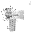
- the invention provides that one to a base 17 of the control device 10 to the rotation axis 18 of the eccentric 13th axially parallel or querab arranged servomotor 16 via a in both directions without self-locking rotatable gear 19 is in drive connection with the eccentric 13, wherein the servo motor 16 is in driving connection with the gear mechanism 19 to achieve the failsafe function in case of failure of the servo motor 16 with the interposition of a rotatable only in servomotor drive direction locking freewheel device 20.
- the drive interruption according to the invention between servomotor 16 and eccentric 13 this can control the friction wheel 8 in frictional engagement with the drive wheel 9 of the coolant pump 4 under the action of the helical spring 14 and freely rotatable toothed gear 19.
- a querab to the axis of rotation 18 of the eccentric 13 on the base 17 via flanges 21,21 'releasably arranged servo motor 16 is available as a gear 19, a worm gear 22 with a multi-course, non-self-locking screw 22' to the free reverse rotation of the eccentric 13 including the drive-connected worm gear 22 to achieve the failsafe function.
- the servomotor 16 Serving as the servomotor 16 is an electric motor, preferably a stepper motor, by means of which the position of the friction wheel 8 separated from the drive wheel 9 is achieved simply and reliably by maintaining the current supply.
- the omission of the energization is sufficient since the eccentric 13 spring-loaded automatically rotates back to restore the drive connection between the friction wheel 8 via the freewheel device 20 assigned to the respective toothed gear 19 or worm gear 22 and drive wheel 9.
- the stepping motor is thus advantageously not to supply any electrical energy, in particular from the electrical system.
- the servo motor 16 or 16 ' can also be provided in an arrangement parallel to the axis of rotation 18 of the eccentric 13, wherein the eccentric 13 is connected via a simple or multi-reduction, not shown spur gear or a not-shown bevel gear under respective interposition of the freewheel device 20 driven by the respective servo motor 16,16 'driven.
- the eccentric 13 is rotatably mounted on the machine side rotationally fixed bearing bush 15 with the front side resting on the base 17 bottom 15 'rotatably, wherein in the bearing bush 15 coaxial with this passing through retaining pin 23 of the control device 10 another Screw spring 24 is arranged.
- This helical torsion spring 24 is connected in parallel to protect the fail-safe function of the control device 10 with the first helical torsion spring 14 by a rotational action rectified on the eccentric 13.
- the friction gear 3 shown in Figure 6 is an electric servomotor 16 or a hydraulic or pneumatic servomotor 16 'axially parallel to the axis of rotation 18 of the unrecognizable eccentric 13 of the control device 10 at the base 17' is arranged.
- the eccentric 13 is in this case socket side equipped with a gear which cooperates with a pinion of a spur gear or angle gear, not shown, wherein the pinion with the interposition of a freewheel device with the rotor of the respective servomotor 16, 16 'is in drive connection.
- the auxiliary unit 4 is preferably a coolant pump of the internal combustion engine 2, wherein the friction wheel 8 of the friction gear 3 is signal-controlled separated by the drive wheel 9 of the coolant pump 4 by a parameter of the internal combustion engine 2 or by means of a map stored in an electronic control unit.
- the friction wheel 8 is held out of engagement by means of an energized stepping motor 16 or by means of a counteracting against a rotation stop hydraulic or pneumatic servo motor 16 '.
Landscapes
- Engineering & Computer Science (AREA)
- General Engineering & Computer Science (AREA)
- Mechanical Engineering (AREA)
- Chemical & Material Sciences (AREA)
- Combustion & Propulsion (AREA)
- Transmission Devices (AREA)
- Arrangement Or Mounting Of Propulsion Units For Vehicles (AREA)
Claims (9)
- Engrenage par friction pour un groupe auxiliaire séparé d'une transmission à courroie de groupes, comprenant une roue d'entraînement (9) du groupe auxiliaire (4) et une roue de friction (8) pouvant être commandée pour former une liaison d'entraînement par adhérence avec la face extérieure (7) de la courroie (5) et la roue d'entraînement (9), et la roue de friction (8) est guidée au moyen d'un bras pivotant (11) logé sur un excentrique (13) d'un dispositif de commande (10) disposé côté machine,
caractérisé en ce que- l'excentrique (13) peut être entraîné en rotation par un moteur à l'encontre d'une précontrainte de ressort,- lors d'une défaillance d'un servomoteur (16, 16'), la liaison d'entraînement des partenaires de friction (8 et 9) étant coupée, la roue de friction (8) guidée par le bras pivotant est commandée par l'excentrique (13) au moyen de la précontrainte de ressort en prise avec la courroie (5) et la roue d'entraînement (9),- un servomoteur (16, 16') disposé sur un socle (17) du dispositif de commande (10) parallèlement à l'axe de celui-ci ou transversalement est en liaison d'entraînement avec l'excentrique (13) par l'intermédiaire d'un engrenage (19, 22) rotatif dans les deux sens de rotation sans blocage automatique,- le servomoteur (16, 16') est en liaison d'entraînement avec l'engrenage (19, 22) par l'intermédiaire d'un dispositif de roue libre (20) bloqué en rotation dans le sens d'entraînement. - Engrenage par friction selon la revendication 1,
caractérisé en ce que
l'engrenage (19) est un engrenage à vis sans fin (22) avec une vis (22') à filetage multiple sans blocage automatique ou un engrenage droit à démultiplication simple ou multiple ou un engrenage angulaire. - Engrenage par friction selon les revendications 1 et 2,
caractérisé en ce qu'
on prévoit un servomoteur (16) électrique ou un servomoteur (16') hydraulique ou pneumatique. - Engrenage par friction selon la revendication 3,
caractérisé en ce que
le servomoteur (16) électrique est un moteur pas à pas. - Engrenage par friction selon les revendications 1 à 4,
caractérisé en ce que- le bras pivotant (11) logé au moyen d'un oeillet (12) sur l'excentrique (13) disposé en rotation côté machine est sollicité au moyen d'un ressort hélicoïdal (14) disposé côté périphérie entre l'oeillet (12) et l'excentrique (13) pour appliquer la roue de friction (8) contre la face extérieure de courroie (7),- le ressort hélicoïdal (14) étant en outre dimensionné de telle sorte que lors d'une défaillance du servomoteur (16, 16') pendant une liaison d'entraînement interrompue de la roue de friction (8) et de la roue d'entraînement (9) et si l'engrenage (19) rotatif librement est découplé du servomoteur (16, 16'), la roue de friction (8) est amenée en position de prise avec la roue d'entraînement (9) par le bras pivotant (11) au moyen de l'excentrique (13) entraîné par ressort. - Engrenage par friction selon la revendication 5,
caractérisé en ce que- l'excentrique (13) est logé mobile en rotation sur un coussinet (15) disposé côté machine immobile en rotation avec un fond (15') reposant côté frontal sur le socle (17),- dans le coussinet (15) un autre ressort hélicoïdal (24) est disposé coaxialement à un boulon de retenue (23) du dispositif de commande (10) traversant le coussinet,- les deux ressorts hélicoïdaux (14, 24) mis en parallèle sont disposés pour agir dans le même sens sur l'excentrique (13). - Engrenage par friction selon les revendications 1 à 6,
caractérisé en ce que
sur l'excentrique (13), côté socle, une vis sans fin (22") fait saillie dans une rainure annulaire (25) du socle (17) et coopère avec une vis sans fin à filetage multiple (22'), qui est en liaison d'entraînement avec le moteur pas à pas (16) bridé transversalement au socle (17). - Engrenage par friction selon les revendications 1 à 6,
caractérisé en ce que
côté socle l'excentrique est muni d'une roue dentée qui coopère avec le pignon d'un engrenage droit ou angulaire, le pignon étant en liaison d'entraînement avec le servomoteur (16, 16') disposé sur le socle parallèlement à l'axe de rotation de l'excentrique par l'intermédiaire d'un dispositif de roue libre. - Engrenage par friction selon l'une quelconque des revendications 1 à 8,
caractérisé en ce que- le groupe auxiliaire (4) est une pompe à réfrigérant du moteur à combustion interne (2),- la roue de friction (8) est, si nécessaire, séparée de la roue d'entraînement (9) de la pompe à réfrigérant (4), grâce à une commande par signal, par un paramètre du moteur à combustion interne (2) ou au moyen d'un champ caractéristique enregistré dans un appareil de commande électronique, et- la roue de friction (8) est maintenue hors prise au moyen d'un moteur pas à pas (16) alimenté en courant ou au moyen d'un servomoteur (16') hydraulique ou pneumatique agissant contre une butée de rotation.
Applications Claiming Priority (3)
| Application Number | Priority Date | Filing Date | Title |
|---|---|---|---|
| DE10309063 | 2003-03-03 | ||
| DE2003109063 DE10309063A1 (de) | 2003-03-03 | 2003-03-03 | Reibradgetriebe für ein von einem Aggregate-Riementrieb einer Brennkraftmaschine gesondert angeordnetes Nebenaggregat |
| PCT/EP2004/000847 WO2004079225A1 (fr) | 2003-03-03 | 2004-01-30 | Engrenage a roue de friction destine a un groupe auxiliaire separe d'un entrainement a courroie de groupe d'un moteur a combustion interne |
Publications (2)
| Publication Number | Publication Date |
|---|---|
| EP1599685A1 EP1599685A1 (fr) | 2005-11-30 |
| EP1599685B1 true EP1599685B1 (fr) | 2006-06-21 |
Family
ID=32945822
Family Applications (1)
| Application Number | Title | Priority Date | Filing Date |
|---|---|---|---|
| EP04706667A Expired - Lifetime EP1599685B1 (fr) | 2003-03-03 | 2004-01-30 | Engrenage a roue de friction destine a un groupe auxiliaire separe d'un entrainement a courroie de groupe d'un moteur a combustion interne |
Country Status (4)
| Country | Link |
|---|---|
| EP (1) | EP1599685B1 (fr) |
| DE (2) | DE10309063A1 (fr) |
| ES (1) | ES2265139T3 (fr) |
| WO (1) | WO2004079225A1 (fr) |
Families Citing this family (14)
| Publication number | Priority date | Publication date | Assignee | Title |
|---|---|---|---|---|
| DE10255079A1 (de) * | 2002-11-26 | 2004-06-03 | Bayerische Motoren Werke Ag | Einem Aggregate-Riementrieb einer Brennkraftmaschine zugeordnetes Reibradgetriebe für ein gesondertes Nebenaggregat |
| EP1464870B1 (fr) * | 2003-04-02 | 2012-08-29 | DAYCO EUROPE S.r.l. | Système de propulsion pour l'entraînement de corps rotatif, en particulier pour pompe à eau d'un moteur à combustion thermique |
| ITTO20030441A1 (it) * | 2003-06-12 | 2004-12-13 | Dayco Europe Srl | Dispositivo di trasmissione a ruota di frizione. |
| DE10346426A1 (de) | 2003-10-07 | 2005-05-19 | Bayerische Motoren Werke Ag | Schwenkarm-Anordnung für ein Reibradgetriebe eines Nebenaggregates einer mit riemengetriebenen Hilfsaggregaten ausgerüsteten Brennkraftmaschine |
| DE10346425A1 (de) | 2003-10-07 | 2005-05-19 | Bayerische Motoren Werke Ag | Reibradgetriebe für ein gesondertes Nebenaggregat einer mit riemengetriebenen Hilfsaggregaten ausgerüsteten Brennkraftmaschine |
| DE602005021197D1 (de) * | 2005-02-28 | 2010-06-24 | Dayco Europe Srl | Reibradaktuator |
| FR2884886B1 (fr) | 2005-04-21 | 2009-04-17 | Renault Sas | Dispositif d'entrainement par friction d'un accessoire de moteur a combustion interne |
| AU2014277796B2 (en) * | 2005-06-20 | 2017-02-23 | Lazer Safe Pty Ltd | Imaging and safety system & method for an industrial machine |
| US8692877B2 (en) | 2005-06-20 | 2014-04-08 | Lazer Safe Pty Ltd | Imaging and safety system and method for an industrial machine |
| EP1896203B1 (fr) * | 2005-06-20 | 2020-08-19 | Lazer Safe Pty Ltd | Systeme et procede d'imagerie et de securite pour machine industrielle |
| CN102767510A (zh) * | 2012-07-30 | 2012-11-07 | 长城汽车股份有限公司 | 实现车辆水泵智能启停的控制系统 |
| DE102013011214B4 (de) * | 2013-07-04 | 2019-12-24 | Audi Ag | Förderpumpenanordnung einer Antriebseinrichtung eines Kraftfahrzeugs sowie Verfahren zum Betreiben einer Förderpumpenanordnung |
| JP6352148B2 (ja) | 2014-10-31 | 2018-07-04 | Ntn株式会社 | 動力伝達ローラ |
| CN106704504A (zh) * | 2017-03-15 | 2017-05-24 | 四川田奥环保科技有限公司 | 一种自适应自动调节的摩擦轮安装驱动装置 |
Family Cites Families (5)
| Publication number | Priority date | Publication date | Assignee | Title |
|---|---|---|---|---|
| DE3934884A1 (de) * | 1989-10-19 | 1991-04-25 | Bayerische Motoren Werke Ag | Endloses zugmittelgetriebe einer brennkraftmaschine |
| DE4039206A1 (de) * | 1990-12-08 | 1992-06-11 | Audi Ag | Antriebsvorrichtung |
| CA2139788A1 (fr) * | 1995-01-09 | 1996-07-10 | John Hugh Kerr | Poulies motrices d'accessoire pour vehicules automobiles, incorporant un embrayage a roue libre en spirale |
| DE19630221C1 (de) * | 1996-07-26 | 1997-08-28 | Daimler Benz Ag | Reibradgetriebe für einen Anlasser einer Verbrennungskraftmaschine |
| JP2000257553A (ja) * | 1999-03-09 | 2000-09-19 | Seiko Seiki Co Ltd | マルチコンプレッサの動力伝達機構 |
-
2003
- 2003-03-03 DE DE2003109063 patent/DE10309063A1/de not_active Withdrawn
-
2004
- 2004-01-30 EP EP04706667A patent/EP1599685B1/fr not_active Expired - Lifetime
- 2004-01-30 WO PCT/EP2004/000847 patent/WO2004079225A1/fr not_active Ceased
- 2004-01-30 DE DE502004000837T patent/DE502004000837D1/de not_active Expired - Lifetime
- 2004-01-30 ES ES04706667T patent/ES2265139T3/es not_active Expired - Lifetime
Also Published As
| Publication number | Publication date |
|---|---|
| EP1599685A1 (fr) | 2005-11-30 |
| WO2004079225A1 (fr) | 2004-09-16 |
| ES2265139T3 (es) | 2007-02-01 |
| DE10309063A1 (de) | 2004-10-14 |
| DE502004000837D1 (de) | 2006-08-03 |
Similar Documents
| Publication | Publication Date | Title |
|---|---|---|
| EP1599685B1 (fr) | Engrenage a roue de friction destine a un groupe auxiliaire separe d'un entrainement a courroie de groupe d'un moteur a combustion interne | |
| DE3734392C2 (de) | Antriebsvorrichtung für Scheibenwischer von Kraftfahrzeugen | |
| DE3642415C2 (fr) | ||
| DE69818946T2 (de) | Vorrichtung zur Steuerung der Drehphase | |
| EP1404956B1 (fr) | Mecanisme de commande a moteur electrique, muni d'une vis sans fin | |
| DE3045504A1 (de) | Wischanlage fuer kraftfahrzeuge | |
| DE102009000772A1 (de) | Einstellvorrichtung zur Einstellung des Verdichtungsverhältnisses einer Hubkolbenbrennkraftmaschine | |
| EP1565671B1 (fr) | Entrainement a courroie pour des accessoires d'un moteur a combustion | |
| DE69100037T2 (de) | Anlasseranordnung fuer verbrennungsmotor. | |
| DE69013569T2 (de) | Schwingende Mähvorrichtung. | |
| DE10135141A1 (de) | Starter | |
| WO2015082221A1 (fr) | Dispositif d'entraînement pour appareil de commande | |
| DE10312982A1 (de) | Scheibenwischvorrichtung, insbesondere für ein Kraftfahrzeug | |
| EP0082298A1 (fr) | Dispositif pour essuyer des glaces d'automobile | |
| WO2003095782A1 (fr) | Mecanisme de commande a moteur electrique | |
| EP2594711B1 (fr) | Dispositif de fermeture électromécanique avec une installation de fermeture rapide | |
| DE69100172T2 (de) | Anlassvorrichtung für Verbrennungsmotor. | |
| DE3740312C2 (de) | Antriebsvorrichtung, insbesondere für eine Scheibenwischeranlage an einem Kraftfahrzeug | |
| DE102019120718A1 (de) | Klappenvorrichtung für einen Kraftwagen | |
| DE19861278B4 (de) | Spindel- oder Schneckenantrieb für Verstelleinrichtungen in Kraftfahrzeugen | |
| DE3600411C2 (fr) | ||
| EP1671052B1 (fr) | Dispositif de reglage | |
| DE60200806T2 (de) | Elektrischer Türantrieb | |
| CH389755A (de) | Nullspannungs-Rückstelleinrichtung an einem elektromotorischen Antrieb für ein mechanisches bzw. hydraulisches Stellglied | |
| EP4222393B1 (fr) | Actionneur, et dispositif pour la mise en prise d'un frein de stationnement d'une transmission automatique de véhicule à moteur ayant un tel actionneur, et véhicule à moteur équipé de celui-ci |
Legal Events
| Date | Code | Title | Description |
|---|---|---|---|
| PUAI | Public reference made under article 153(3) epc to a published international application that has entered the european phase |
Free format text: ORIGINAL CODE: 0009012 |
|
| 17P | Request for examination filed |
Effective date: 20050716 |
|
| AK | Designated contracting states |
Kind code of ref document: A1 Designated state(s): AT BE BG CH CY CZ DE DK EE ES FI FR GB GR HU IE IT LI LU MC NL PT RO SE SI SK TR |
|
| AX | Request for extension of the european patent |
Extension state: AL LT LV MK |
|
| GRAP | Despatch of communication of intention to grant a patent |
Free format text: ORIGINAL CODE: EPIDOSNIGR1 |
|
| RBV | Designated contracting states (corrected) |
Designated state(s): DE ES FR GB IT |
|
| DAX | Request for extension of the european patent (deleted) | ||
| GRAS | Grant fee paid |
Free format text: ORIGINAL CODE: EPIDOSNIGR3 |
|
| GRAA | (expected) grant |
Free format text: ORIGINAL CODE: 0009210 |
|
| AK | Designated contracting states |
Kind code of ref document: B1 Designated state(s): DE ES FR GB IT |
|
| PG25 | Lapsed in a contracting state [announced via postgrant information from national office to epo] |
Ref country code: IT Free format text: LAPSE BECAUSE OF FAILURE TO SUBMIT A TRANSLATION OF THE DESCRIPTION OR TO PAY THE FEE WITHIN THE PRESCRIBED TIME-LIMIT;WARNING: LAPSES OF ITALIAN PATENTS WITH EFFECTIVE DATE BEFORE 2007 MAY HAVE OCCURRED AT ANY TIME BEFORE 2007. THE CORRECT EFFECTIVE DATE MAY BE DIFFERENT FROM THE ONE RECORDED. Effective date: 20060621 |
|
| REG | Reference to a national code |
Ref country code: GB Ref legal event code: FG4D Free format text: NOT ENGLISH |
|
| REF | Corresponds to: |
Ref document number: 502004000837 Country of ref document: DE Date of ref document: 20060803 Kind code of ref document: P |
|
| GBT | Gb: translation of ep patent filed (gb section 77(6)(a)/1977) |
Effective date: 20060721 |
|
| ET | Fr: translation filed | ||
| REG | Reference to a national code |
Ref country code: ES Ref legal event code: FG2A Ref document number: 2265139 Country of ref document: ES Kind code of ref document: T3 |
|
| PLBE | No opposition filed within time limit |
Free format text: ORIGINAL CODE: 0009261 |
|
| STAA | Information on the status of an ep patent application or granted ep patent |
Free format text: STATUS: NO OPPOSITION FILED WITHIN TIME LIMIT |
|
| 26N | No opposition filed |
Effective date: 20070322 |
|
| REG | Reference to a national code |
Ref country code: FR Ref legal event code: PLFP Year of fee payment: 13 |
|
| REG | Reference to a national code |
Ref country code: FR Ref legal event code: PLFP Year of fee payment: 14 |
|
| REG | Reference to a national code |
Ref country code: FR Ref legal event code: PLFP Year of fee payment: 15 |
|
| PGFP | Annual fee paid to national office [announced via postgrant information from national office to epo] |
Ref country code: FR Payment date: 20230123 Year of fee payment: 20 Ref country code: ES Payment date: 20230216 Year of fee payment: 20 |
|
| PGFP | Annual fee paid to national office [announced via postgrant information from national office to epo] |
Ref country code: IT Payment date: 20230131 Year of fee payment: 20 Ref country code: GB Payment date: 20230124 Year of fee payment: 20 Ref country code: DE Payment date: 20230110 Year of fee payment: 20 |
|
| P01 | Opt-out of the competence of the unified patent court (upc) registered |
Effective date: 20230503 |
|
| REG | Reference to a national code |
Ref country code: DE Ref legal event code: R071 Ref document number: 502004000837 Country of ref document: DE |
|
| REG | Reference to a national code |
Ref country code: ES Ref legal event code: FD2A Effective date: 20240206 |
|
| REG | Reference to a national code |
Ref country code: GB Ref legal event code: PE20 Expiry date: 20240129 |
|
| PG25 | Lapsed in a contracting state [announced via postgrant information from national office to epo] |
Ref country code: ES Free format text: LAPSE BECAUSE OF EXPIRATION OF PROTECTION Effective date: 20240131 |
|
| PG25 | Lapsed in a contracting state [announced via postgrant information from national office to epo] |
Ref country code: ES Free format text: LAPSE BECAUSE OF EXPIRATION OF PROTECTION Effective date: 20240131 Ref country code: GB Free format text: LAPSE BECAUSE OF EXPIRATION OF PROTECTION Effective date: 20240129 |