EP1565671B1 - Entrainement a courroie pour des accessoires d'un moteur a combustion - Google Patents
Entrainement a courroie pour des accessoires d'un moteur a combustion Download PDFInfo
- Publication number
- EP1565671B1 EP1565671B1 EP03757980A EP03757980A EP1565671B1 EP 1565671 B1 EP1565671 B1 EP 1565671B1 EP 03757980 A EP03757980 A EP 03757980A EP 03757980 A EP03757980 A EP 03757980A EP 1565671 B1 EP1565671 B1 EP 1565671B1
- Authority
- EP
- European Patent Office
- Prior art keywords
- eccentric
- belt drive
- wheel
- unit
- servomotor
- Prior art date
- Legal status (The legal status is an assumption and is not a legal conclusion. Google has not performed a legal analysis and makes no representation as to the accuracy of the status listed.)
- Expired - Lifetime
Links
- 238000002485 combustion reaction Methods 0.000 title claims description 19
- 239000002826 coolant Substances 0.000 claims description 13
- 239000002184 metal Substances 0.000 claims description 3
- 108010001267 Protein Subunits Proteins 0.000 claims 1
- 230000006835 compression Effects 0.000 description 2
- 238000007906 compression Methods 0.000 description 2
- 230000001133 acceleration Effects 0.000 description 1
- 238000001816 cooling Methods 0.000 description 1
- 238000005538 encapsulation Methods 0.000 description 1
- 230000004048 modification Effects 0.000 description 1
- 238000012986 modification Methods 0.000 description 1
- 230000000149 penetrating effect Effects 0.000 description 1
- 230000002787 reinforcement Effects 0.000 description 1
- 230000000284 resting effect Effects 0.000 description 1
Images



Classifications
-
- F—MECHANICAL ENGINEERING; LIGHTING; HEATING; WEAPONS; BLASTING
- F16—ENGINEERING ELEMENTS AND UNITS; GENERAL MEASURES FOR PRODUCING AND MAINTAINING EFFECTIVE FUNCTIONING OF MACHINES OR INSTALLATIONS; THERMAL INSULATION IN GENERAL
- F16H—GEARING
- F16H7/00—Gearings for conveying rotary motion by endless flexible members
- F16H7/02—Gearings for conveying rotary motion by endless flexible members with belts; with V-belts
-
- F—MECHANICAL ENGINEERING; LIGHTING; HEATING; WEAPONS; BLASTING
- F01—MACHINES OR ENGINES IN GENERAL; ENGINE PLANTS IN GENERAL; STEAM ENGINES
- F01P—COOLING OF MACHINES OR ENGINES IN GENERAL; COOLING OF INTERNAL-COMBUSTION ENGINES
- F01P5/00—Pumping cooling-air or liquid coolants
- F01P5/10—Pumping liquid coolant; Arrangements of coolant pumps
- F01P5/12—Pump-driving arrangements
-
- F—MECHANICAL ENGINEERING; LIGHTING; HEATING; WEAPONS; BLASTING
- F02—COMBUSTION ENGINES; HOT-GAS OR COMBUSTION-PRODUCT ENGINE PLANTS
- F02B—INTERNAL-COMBUSTION PISTON ENGINES; COMBUSTION ENGINES IN GENERAL
- F02B67/00—Engines characterised by the arrangement of auxiliary apparatus not being otherwise provided for, e.g. the apparatus having different functions; Driving auxiliary apparatus from engines, not otherwise provided for
- F02B67/04—Engines characterised by the arrangement of auxiliary apparatus not being otherwise provided for, e.g. the apparatus having different functions; Driving auxiliary apparatus from engines, not otherwise provided for of mechanically-driven auxiliary apparatus
- F02B67/06—Engines characterised by the arrangement of auxiliary apparatus not being otherwise provided for, e.g. the apparatus having different functions; Driving auxiliary apparatus from engines, not otherwise provided for of mechanically-driven auxiliary apparatus driven by means of chains, belts, or like endless members
-
- F—MECHANICAL ENGINEERING; LIGHTING; HEATING; WEAPONS; BLASTING
- F16—ENGINEERING ELEMENTS AND UNITS; GENERAL MEASURES FOR PRODUCING AND MAINTAINING EFFECTIVE FUNCTIONING OF MACHINES OR INSTALLATIONS; THERMAL INSULATION IN GENERAL
- F16H—GEARING
- F16H13/00—Gearing for conveying rotary motion with constant gear ratio by friction between rotary members
- F16H13/10—Means for influencing the pressure between the members
-
- F—MECHANICAL ENGINEERING; LIGHTING; HEATING; WEAPONS; BLASTING
- F01—MACHINES OR ENGINES IN GENERAL; ENGINE PLANTS IN GENERAL; STEAM ENGINES
- F01P—COOLING OF MACHINES OR ENGINES IN GENERAL; COOLING OF INTERNAL-COMBUSTION ENGINES
- F01P7/00—Controlling of coolant flow
- F01P7/14—Controlling of coolant flow the coolant being liquid
- F01P7/16—Controlling of coolant flow the coolant being liquid by thermostatic control
- F01P7/162—Controlling of coolant flow the coolant being liquid by thermostatic control by cutting in and out of pumps
Definitions
- the invention relates to an aggregate belt drive of an internal combustion engine with a friction gear with control device and auxiliary unit, wherein the friction gear comprises a frictionally engaged in a Umschlingungs Scheme a belt of a drive wheel of the engine or other unit with the outside of the belt friction wheel and a with this friction wheel frictionally driven drive wheel of the separately arranged auxiliary unit, wherein the friction wheel is controlled by means of a control device, if necessary, in and out of engagement with the belt or the drive wheel.
- German patent application P 102 36 746 such an arrangement has been described by means of basic illustrations, However, without a concretely designed control device for a switch off and switchable friction wheel for variable drive of the auxiliary unit show.
- the reliability of the control device according to the invention is achieved by means of the coarse thread under spring action automatically in a connection of the accessory effecting position from which the eccentric is controlled by switched servo motor in one of the shutdown of the accessory serving counter position to remove the friction wheel from the accessory drive wheel.
- control device advantageously causes constant engagement of the friction wheel with the belt of the belt drive as well as with the drive wheel of the auxiliary device, no failure harmful to the operation of the internal combustion engine is disadvantageous if the servomotor fails. That is, for example, serving as a coolant pump of the engine accessory that this z. B. at cold start of the engine is not switched off and thus the internal combustion engine only has to deliver more power, but the coolant circulation is secured in any case.
- a friction gear 3 is provided for a separately arranged on the internal combustion engine 2 auxiliary unit 4, which is in particular a coolant pump for the cooling circuit of the internal combustion engine 2.
- the friction gear 3 comprises a friction wheel 8, which frictionally cooperates with the outer side 7 of the belt 5 in a looping region of the belt 5 of a crankshaft side drive wheel 6 and a drive wheel 9 of the coolant pump 4 which can be driven frictionally with the friction wheel 8.
- the friction wheel 8 is controlled by means of a control device 10 is controlled in particular in a cold start of the internal combustion engine 2 out of engagement with the pump-side drive wheel 9.
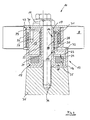
- the friction wheel 8 is connected via a pivot arm 11 arranged in a machine-mounted receptacle 12 eccentric 13 in conjunction, the eccentric 13 is guided in the receptacle 12 via a coarse thread 14 such that one out the caused against a spring resistance by means of a servo motor 15 lifting movement of the Eccentric 13 forcibly coupled rotational movement of the eccentric 13 of the control of the associated with the friction wheel 8 pivot arm 11 for switching off / on the coolant pump 4 is used.
- a compact and smooth-running control device 10 is achieved with a designed as a pot-shaped housing 16 receptacle 12 with a central tubular extension 17 with arranged on the outer circumference first threads 18 for a ball screw 19, wherein the secured in a cylindrical cage 20 threaded balls in the inner circumference of the eccentric thirteenth penetrating aperture 21 arranged second threads 22 engage.
- the eccentric 13 is rotatably guided in the housing 16 via a centering collar 23, and further is arranged to support a compact design of the free end face 24 of the Zentrierbundes 23 opposite the housing 16, a switchable solenoid 25 as a servo motor 15.
- a switchable solenoid 25 as a servo motor 15.
- one eye 26 of the pivoting arm 11 is arranged on the eccentric 13 so drivingly acting helical spring 27 is arranged that the eccentric 13 via the coarse thread 14 with de-energized electromagnet 25 on the one hand held at this stroke distance and the other at the same time in a the friction wheel is rotated in operative engagement with the drive wheel 9 of the coolant pump 4 holding position.
- One of the compact design of the control device 10 conducive arrangement provides that in the eye 26 formed of a plastic pivot arm 11 against a shoulder 28 of a arranged in the eye 26 for reinforcement metal housing 29 on the one hand fitting screw torsion 27 on the other hand via a in the metal housing 29th centered with game and axially secured to the eccentric 13 connected via a screw 30 cover 31.
- Fig.2 which is arranged with a rotational bias coil spring 27 at one end to the eccentric 13 and the other end to the eye 26 of the pivot arm 11 each rotatably connected.
- the above-described spring arrangement enables a high level of operational reliability in that by means of the helical torsion spring 27 via electromagnets 25, the eccentric 13 is rotated via the coarse thread 14 into a position by means of which the friction wheel 8 guided equidistantly to the drive wheel 6 on the outside of the belt 7 under tensile load the swing arm 11 is brought and held in frictional engagement with the drive wheel 9.
- the coolant pump 4 thus advantageously remains in drive connection via the friction gear 3 with the belt drive 1.
- the inventively preferred tensile load of the pivot arm 11 for the frictional engagement of the friction wheel 8 with the drive wheel 9 allows in an advantageous manner Way a lightweight pivot arm 11.
- a servo motor side with the eccentric 13 rotatably connected lid 32 is provided and on the other hand on the tube extension 17 frontally resting, non-rotatably secured end cover 33, wherein the entire control device 10 including the friction wheel 8 supporting the swing arm 11 by means of a Lid 31, 32, 33 and the tube extension 17 passing through bolts 34 on a machine-side slug 35 frontally of the engine 2 in the open Region between drive wheel 6 and adjacent drive wheel 9 of the coolant pump 4 is arranged.
- This advantageous space utilization is achieved with the invention small-sized control device 10.
- FIG. 5 shows in a modification of a control device 10 ', in which the receptacle 12' is a cup-shaped housing 36 with a central, penetrated by a fastening bolt 37 tube extension 38 to the coaxial one acting on the eccentric 39 compression spring 40 is arranged, wherein the eccentric 39 guided via an interposed ball - steep thread 41 guided between its outer circumference and the inner circumference of the outer wall 42 of the housing 36 rotatable and liftable by means of a servo motor 43 in operative connection with the compression spring 40.
- the receptacle 12' is a cup-shaped housing 36 with a central, penetrated by a fastening bolt 37 tube extension 38 to the coaxial one acting on the eccentric 39 compression spring 40 is arranged, wherein the eccentric 39 guided via an interposed ball - steep thread 41 guided between its outer circumference and the inner circumference of the outer wall 42 of the housing 36 rotatable and liftable by means of a servo motor 43 in operative connection with the compression spring 40.
- the auxiliary unit 4 is preferably a coolant pump serving for the internal combustion engine 2, the friction wheel 8 of which is controlled via the mechanism of the respective control device 10, 10 'in engagement with the coolant pump drive wheel 9 and is kept in engagement, as required, either by a parameter Internal combustion engine 2 or by a map of a Motronic driven servomotor 15 is disengaged. This may be the case in particular when the internal combustion engine 2 is cold-starting, and it is also conceivable in its high-speed range, preferably in an intermittent connection and disconnection.
Landscapes
- Engineering & Computer Science (AREA)
- General Engineering & Computer Science (AREA)
- Mechanical Engineering (AREA)
- Chemical & Material Sciences (AREA)
- Combustion & Propulsion (AREA)
- Transmission Devices (AREA)
- Devices For Conveying Motion By Means Of Endless Flexible Members (AREA)
Claims (9)
- Unité d'entraînement à courroie de moteur à combustion interne comportant une transmission à roue à friction et une installation de commande ainsi qu'un accessoire,- la transmission à roue à friction (3) comprend une roue à friction (8) coopérant par friction avec le côté extérieur (7) de la courroie (5), dans la zone d'enveloppement de la courroie (5) d'une roue d'entraînement (6) du moteur à combustion (2) ou d'une autre unité, ainsi qu'une roue d'entraînement (9) de l'accessoire (4), entraînée par friction par cette roue à friction (8),caractérisée en ce que- la roue à friction (8) est commandée par une installation de commande (10, 10') pour être, à la demande, mise en prise ou hors de prise de la courroie (5) ou de la roue d'entraînement (9),- la roue à friction (8) est reliée par un bras pivotant (11, 11') avec un excentrique (13, 39) de l'installation de commande (10, 10'), cet excentrique étant dans un logement (12, 12') fixe, côté moteur à combustion, et- l'excentrique (13, 39) est monté de façon guidée dans le logement (12, 12') par un filetage à pas rapide (14, 41) de façon que,- un mouvement de rotation couplé de force à un mouvement de translation de l'excentrique (13, 39) produit par un servomoteur (15, 43) de l'installation de commande (10, 10') contre une résistance de ressort, pour le bras pivotant (11, 11') relié à la roue à friction (8) serve au branchement/à la coupure de l'accessoire (4).
- Unité d'entraînement à courroie selon la revendication 1,
caractérisée en ce que- le logement (12) est un boîtier (16) en forme de pot, ayant un prolongement tubulaire centré (17) dont la périphérie extérieure est munie de premiers filets (18) pour une vis à billes (19),- les billes de la vis étant fixées dans une cage cylindrique (20) venant en prise dans des seconds filets (22) de la périphérie intérieure d'un passage (21) traversant l'excentrique (13). - Unité d'entraînement à courroie selon la revendication 2,
caractérisée en ce que- l'excentrique (13) est guidé en rotation dans le boîtier (16) par l'intermédiaire d'une collerette de centrage (23), et- un électro-aimant (25) commutable fonctionnant comme servomoteur (15) est prévu au niveau de la surface frontale libre (24) de la collerette de centrage (23) en regard du boîtier (16), et dans celui-ci- l'excentrique (13) est maintenu à distance par rapport à un électro-aimant (25) non alimenté/servomoteur (15) par l'intermédiaire d'un ressort hélicoïdal (27) agissant dans le sens de l'entraînement sur l'excentrique (13) par l'intermédiaire d'un oeillet (26) du bras pivotant (11). - Unité d'entraînement à courroie selon les revendications 2 et 3,
caractérisée en ce que- le ressort hélicoïdal (27) est maintenu fixé axialement dans l'oeillet (26) du bras pivotant (11) en matière plastique, contre d'une part, un épaulement (28) d'un boîtier métallique (29) logé dans l'oeillet (26) et d'autre part, avec un couvercle (31) centré avec du jeu dans le boîtier métallique (29) de l'oeillet (26), et relié à l'excentrique (13) par un moyen de vissage (30), et- le ressort hélicoïdal (27) installé avec précontrainte en rotation, est relié solidairement en rotation au niveau d'une extrémité avec l'excentrique (13) et au niveau de l'autre extrémité, avec l'oeillet (26) du bras pivotant (11). - Unité d'entraînement à courroie selon les revendications 2 à 4,
caractérisée en ce que- l'excentrique (13) est tourné par l'intermédiaire de son filetage à pas rapide (14) dans une position par le ressort hélicoïdal (27) grâce à sa précontrainte de rotation lorsque l'électro-aimant (25) est coupé du courant/ servomoteur (15), position dans laquelle,- la roue à friction (8) guidée de manière équidistante par rapport à la roue à friction (6) respective, est mise et maintenue en prise de friction avec la roue motrice (9) par la contrainte en traction du bras pivotant (11). - Unité d'entraînement à courroie selon les revendications 2 à 5,
caractérisée en ce qu'- en cas d'électro-aimant (25) coupé du courant, l'excentrique (13) est tourné dans une position opposée par le filetage à pas rapide (814) de façon que,- la roue à friction (8) est mise hors de prise par le bras pivotant (11) par rapport à la roue d'entraînement (9) et est maintenue ainsi et- le ressort hélicoïdal (27) agissant sur le bras pivotant (11) par sa précontrainte en rotation, est pressé de manière guidée contre le côté extérieur (7) de la courroie, à équidistance dans la zone d'enveloppement de la roue d'entraînement (6) respective pour un fonctionnement en roue libre avec liaison par friction. - Unité d'entraînement à courroie selon les revendications 2 à 6,
caractérisée en ce que- pour encapsuler l'oeillet (26) du côté du servomoteur, un couvercle (32) est relié solidairement en rotation à l'excentrique (13), et- d'autre part, un couvercle de fermeture (33) fixé solidairement en rotation est appliqué sur le côté frontal du prolongement tubulaire (17), et- l'ensemble de l'installation de commande (10) est prévu sur un relief (35) côté machine en étant fixé par une vis (34) traversant les couvercles (31, 32, 33) et le prolongement tubulaire (17). - Unité d'entraînement à courroie selon la revendication 1,
caractérisée en ce que- le logement (12') est un boîtier (36) en forme de pot, muni d'un prolongement tubulaire (38) centré, traversant un goujon de fixation (37) et pour lequel,- un ressort de compression (40) à action axiale est installé coaxialement sur l'excentrique (39) et pour lequel,- l'excentrique (13) est installé par l'intermédiaire d'un filetage à pas rapide (41) à billes, interposé entre sa périphérie extérieure et la périphérie intérieure de la paroi extérieure (42) du boîtier (36), de manière guidée et mobile en rotation et en translation par l'intermédiaire d'un servomoteur (43) en liaison avec le ressort de compression (40). - Unité d'entraînement à courroie selon les revendications 2 à 8,
caractérisée en ce que- l'accessoire (4) du moteur à combustion (2) est sa pompe de liquide de refroidissement dont- la roue à friction (8) est mise hors de prise de la roue à friction (9) par l'intermédiaire du servomoteur (15) en fonction d'un paramètre du moteur à combustion (2) ou par une commande selon un champ de caractéristiques enregistrées dans l'électronique du moteur et- le servomoteur (15) est un électro-aimant commutable (25).
Applications Claiming Priority (3)
| Application Number | Priority Date | Filing Date | Title |
|---|---|---|---|
| DE10255075 | 2002-11-26 | ||
| DE2002155075 DE10255075A1 (de) | 2002-11-26 | 2002-11-26 | In einem Riementrieb für Aggregate einer Brennkraftmaschine vorgesehenes Reibradgetriebe für ein gesondertes Nebenaggregat |
| PCT/EP2003/011404 WO2004048808A1 (fr) | 2002-11-26 | 2003-10-15 | Engrenage a roue de friction dispose dans un mecanisme d'entrainement par courroie, destine aux unites d'un moteur a combustion interne et a une unite auxiliaire separee |
Publications (2)
| Publication Number | Publication Date |
|---|---|
| EP1565671A1 EP1565671A1 (fr) | 2005-08-24 |
| EP1565671B1 true EP1565671B1 (fr) | 2010-02-24 |
Family
ID=32240429
Family Applications (1)
| Application Number | Title | Priority Date | Filing Date |
|---|---|---|---|
| EP03757980A Expired - Lifetime EP1565671B1 (fr) | 2002-11-26 | 2003-10-15 | Entrainement a courroie pour des accessoires d'un moteur a combustion |
Country Status (3)
| Country | Link |
|---|---|
| EP (1) | EP1565671B1 (fr) |
| DE (2) | DE10255075A1 (fr) |
| WO (1) | WO2004048808A1 (fr) |
Families Citing this family (15)
| Publication number | Priority date | Publication date | Assignee | Title |
|---|---|---|---|---|
| DE10255079A1 (de) * | 2002-11-26 | 2004-06-03 | Bayerische Motoren Werke Ag | Einem Aggregate-Riementrieb einer Brennkraftmaschine zugeordnetes Reibradgetriebe für ein gesondertes Nebenaggregat |
| DE10309062A1 (de) | 2003-03-03 | 2004-09-16 | Bayerische Motoren Werke Ag | Reibrad eines Reibradgetriebes für ein von einem Aggregate-Riementrieb einer Brennkraftmaschine gesondert angeordnetes Nebenaggregat |
| DE10309061A1 (de) | 2003-03-03 | 2004-10-14 | Bayerische Motoren Werke Ag | Mit einem Aggregate-Riementrieb einer Brennkraftmaschine zusammenwirkendes Reibradgetriebe für ein gesondert angeordnetes Nebenaggregat |
| EP1464870B1 (fr) * | 2003-04-02 | 2012-08-29 | DAYCO EUROPE S.r.l. | Système de propulsion pour l'entraînement de corps rotatif, en particulier pour pompe à eau d'un moteur à combustion thermique |
| ITTO20030441A1 (it) * | 2003-06-12 | 2004-12-13 | Dayco Europe Srl | Dispositivo di trasmissione a ruota di frizione. |
| DE10330672B4 (de) * | 2003-07-08 | 2006-10-12 | Bayerische Motoren Werke Ag | Riementrieb für Hilfsaggregate einer Brennkraftmaschine |
| DE10346426A1 (de) * | 2003-10-07 | 2005-05-19 | Bayerische Motoren Werke Ag | Schwenkarm-Anordnung für ein Reibradgetriebe eines Nebenaggregates einer mit riemengetriebenen Hilfsaggregaten ausgerüsteten Brennkraftmaschine |
| DE10346425A1 (de) | 2003-10-07 | 2005-05-19 | Bayerische Motoren Werke Ag | Reibradgetriebe für ein gesondertes Nebenaggregat einer mit riemengetriebenen Hilfsaggregaten ausgerüsteten Brennkraftmaschine |
| DE602005021197D1 (de) * | 2005-02-28 | 2010-06-24 | Dayco Europe Srl | Reibradaktuator |
| FR2884886B1 (fr) | 2005-04-21 | 2009-04-17 | Renault Sas | Dispositif d'entrainement par friction d'un accessoire de moteur a combustion interne |
| US9334932B2 (en) | 2011-05-13 | 2016-05-10 | Litens Automotive Partnership | Intelligent belt drive system and method |
| US9464697B2 (en) | 2011-09-05 | 2016-10-11 | Litens Automotive Partnership | Intelligent belt drive system and method |
| US9447850B2 (en) | 2012-04-28 | 2016-09-20 | Litens Automotive Partnership | Adjustable tensioner |
| WO2016199186A1 (fr) * | 2015-06-08 | 2016-12-15 | 日産自動車株式会社 | Dispositif d'entraînement d'accessoire pour véhicule |
| JP6344529B2 (ja) * | 2015-06-22 | 2018-06-20 | 日産自動車株式会社 | 車両用補機駆動装置 |
Family Cites Families (10)
| Publication number | Priority date | Publication date | Assignee | Title |
|---|---|---|---|---|
| US1391572A (en) * | 1919-01-24 | 1921-09-20 | Thomas B Nickel | Pump-operating mechanism |
| GB461603A (en) * | 1936-07-20 | 1937-02-19 | Karl Metzger | Improvements in or relating to air-conditioning systems in motor vehicles |
| US2823546A (en) * | 1952-06-27 | 1958-02-18 | Barrett Walter William Henry | Coupling for the transmission of rotary motion |
| CH492247A (fr) * | 1967-12-27 | 1970-02-27 | Piquerez Sa Ervin | Boîte de montre étanche |
| DE3225388A1 (de) * | 1982-07-07 | 1984-01-12 | Robert Bosch Gmbh, 7000 Stuttgart | Vorrichtung zum antrieb von hilfsaggregaten von kraftfahrzeugen |
| US4822321A (en) * | 1988-07-18 | 1989-04-18 | General Motors Corporation | Combination water pump and belt tensioner |
| DE3934884A1 (de) | 1989-10-19 | 1991-04-25 | Bayerische Motoren Werke Ag | Endloses zugmittelgetriebe einer brennkraftmaschine |
| DE4039206A1 (de) * | 1990-12-08 | 1992-06-11 | Audi Ag | Antriebsvorrichtung |
| DE19727914A1 (de) * | 1997-07-01 | 1999-01-07 | Bayerische Motoren Werke Ag | Schlupfkupplung für ein antreibbares Aggregat, insbesondere Nebenaggregat einer Brennkraftmaschine |
| DE10236746A1 (de) | 2002-08-10 | 2004-02-19 | Bayerische Motoren Werke Ag | Brennkraftmaschine mit einer Antriebsanordnung für Aggregat-Module |
-
2002
- 2002-11-26 DE DE2002155075 patent/DE10255075A1/de not_active Ceased
-
2003
- 2003-10-15 DE DE50312456T patent/DE50312456D1/de not_active Expired - Lifetime
- 2003-10-15 EP EP03757980A patent/EP1565671B1/fr not_active Expired - Lifetime
- 2003-10-15 WO PCT/EP2003/011404 patent/WO2004048808A1/fr not_active Ceased
Also Published As
| Publication number | Publication date |
|---|---|
| EP1565671A1 (fr) | 2005-08-24 |
| DE10255075A1 (de) | 2004-06-03 |
| DE50312456D1 (de) | 2010-04-08 |
| WO2004048808A1 (fr) | 2004-06-10 |
Similar Documents
| Publication | Publication Date | Title |
|---|---|---|
| EP1565671B1 (fr) | Entrainement a courroie pour des accessoires d'un moteur a combustion | |
| DE4315826C5 (de) | Motor-Pumpen-Aggregat | |
| DE4401074B4 (de) | Pumpenanordnung, insbesondere zur Förderung von Kraftstoff aus einem Vorratsbehälter zu einer Brennkraftmaschine | |
| EP1414636B1 (fr) | Entrainement lineaire electromecanique | |
| DE69800206T2 (de) | Hochbelastbarer viskose Ventilatorantrieb sowie Haltevorrichtung dafür | |
| DE10311037B4 (de) | Elektrische Ölpumpenvorrichtung | |
| EP1188003A1 (fr) | Dispositif de tension pour moyens d'entrainement tels que courroies ou chaines | |
| EP0855515A1 (fr) | Pompe, en particulier pompe de refroidissement réglable, pour véhicules | |
| DE3503471A1 (de) | Foerdermengen-steuervorrichtung fuer einen kuehlmittelverdichter mit foerdermengen-einstellvorrichtung | |
| DE69717244T2 (de) | Pumpvorrichtung zum Zuführen von Kraftstoff von einem Tank zu einer Brennkraftmaschine | |
| DE102021125611A1 (de) | Elektromechanischer Betätigungsaktor und Verfahren zum Betreiben eines elektromechanischen Betätigungsaktors | |
| DE102005047203A1 (de) | Brennkraftmaschine mit variablem Verdichtungsverhältnis | |
| DE202022002768U1 (de) | Elektromechanischer Betätigungsaktor | |
| WO2004048759A1 (fr) | Mecanisme d'entrainement par courroie pour unites auxiliaires d'un moteur a combustion interne | |
| EP1381744B1 (fr) | Cylindre de blocage | |
| DE10309063A1 (de) | Reibradgetriebe für ein von einem Aggregate-Riementrieb einer Brennkraftmaschine gesondert angeordnetes Nebenaggregat | |
| DE202008011202U1 (de) | Reibschaltkupplung mit einem von einem Antriebsmotor über einen Antriebsriemen angetriebenen Antriebsrad und Antriebseinheit | |
| EP1671050B1 (fr) | Ensemble bras articule pour un engranage a friction d'un groupe secondaire d'un moteur a combustion interne equipe de groupes auxiliares entraines par courroie | |
| EP1565672B1 (fr) | Entraînement à courroie pour des accessoires d'un moteur à combustion | |
| EP3077676A1 (fr) | Pompe réglable pour moteur à combustion interne | |
| EP1455064B1 (fr) | Entraînement à courroie d'un moteur avec entraînement par friction de roue avec un contrôleur et un accessoire de moteur | |
| DE29716110U1 (de) | Magnetkupplungspumpe | |
| DE69000833T2 (de) | Vorrichtung zur verstellung des vorhubs einer kraftstoffeinspritzpumpe. | |
| DE19843120C1 (de) | Verstellbare Radialkolbenmaschine | |
| WO2013056855A1 (fr) | Pompe à liquide de refroidissement réglable |
Legal Events
| Date | Code | Title | Description |
|---|---|---|---|
| PUAI | Public reference made under article 153(3) epc to a published international application that has entered the european phase |
Free format text: ORIGINAL CODE: 0009012 |
|
| 17P | Request for examination filed |
Effective date: 20050211 |
|
| AK | Designated contracting states |
Kind code of ref document: A1 Designated state(s): AT BE BG CH CY CZ DE DK EE ES FI FR GB GR HU IE IT LI LU MC NL PT RO SE SI SK TR |
|
| RBV | Designated contracting states (corrected) |
Designated state(s): DE ES FR GB IT |
|
| 17Q | First examination report despatched |
Effective date: 20080320 |
|
| RTI1 | Title (correction) |
Free format text: ACCESSORIES BELT DRIVE OF AN INTERNAL COMBUSTION ENGINE |
|
| GRAP | Despatch of communication of intention to grant a patent |
Free format text: ORIGINAL CODE: EPIDOSNIGR1 |
|
| RTI1 | Title (correction) |
Free format text: ACCESSORIES BELT DRIVE OF AN INTERNAL COMBUSTION ENGINE |
|
| GRAS | Grant fee paid |
Free format text: ORIGINAL CODE: EPIDOSNIGR3 |
|
| GRAA | (expected) grant |
Free format text: ORIGINAL CODE: 0009210 |
|
| AK | Designated contracting states |
Kind code of ref document: B1 Designated state(s): DE ES FR GB IT |
|
| REG | Reference to a national code |
Ref country code: GB Ref legal event code: FG4D Free format text: NOT ENGLISH |
|
| REF | Corresponds to: |
Ref document number: 50312456 Country of ref document: DE Date of ref document: 20100408 Kind code of ref document: P |
|
| PG25 | Lapsed in a contracting state [announced via postgrant information from national office to epo] |
Ref country code: ES Free format text: LAPSE BECAUSE OF FAILURE TO SUBMIT A TRANSLATION OF THE DESCRIPTION OR TO PAY THE FEE WITHIN THE PRESCRIBED TIME-LIMIT Effective date: 20100604 |
|
| PLBE | No opposition filed within time limit |
Free format text: ORIGINAL CODE: 0009261 |
|
| STAA | Information on the status of an ep patent application or granted ep patent |
Free format text: STATUS: NO OPPOSITION FILED WITHIN TIME LIMIT |
|
| 26N | No opposition filed |
Effective date: 20101125 |
|
| PG25 | Lapsed in a contracting state [announced via postgrant information from national office to epo] |
Ref country code: IT Free format text: LAPSE BECAUSE OF FAILURE TO SUBMIT A TRANSLATION OF THE DESCRIPTION OR TO PAY THE FEE WITHIN THE PRESCRIBED TIME-LIMIT Effective date: 20100224 |
|
| REG | Reference to a national code |
Ref country code: FR Ref legal event code: PLFP Year of fee payment: 13 |
|
| REG | Reference to a national code |
Ref country code: FR Ref legal event code: PLFP Year of fee payment: 14 |
|
| REG | Reference to a national code |
Ref country code: FR Ref legal event code: PLFP Year of fee payment: 15 |
|
| REG | Reference to a national code |
Ref country code: FR Ref legal event code: PLFP Year of fee payment: 16 |
|
| PGFP | Annual fee paid to national office [announced via postgrant information from national office to epo] |
Ref country code: FR Payment date: 20221020 Year of fee payment: 20 |
|
| PGFP | Annual fee paid to national office [announced via postgrant information from national office to epo] |
Ref country code: GB Payment date: 20221024 Year of fee payment: 20 Ref country code: DE Payment date: 20220621 Year of fee payment: 20 |
|
| P01 | Opt-out of the competence of the unified patent court (upc) registered |
Effective date: 20230502 |
|
| REG | Reference to a national code |
Ref country code: DE Ref legal event code: R071 Ref document number: 50312456 Country of ref document: DE |
|
| REG | Reference to a national code |
Ref country code: GB Ref legal event code: PE20 Expiry date: 20231014 |
|
| PG25 | Lapsed in a contracting state [announced via postgrant information from national office to epo] |
Ref country code: GB Free format text: LAPSE BECAUSE OF EXPIRATION OF PROTECTION Effective date: 20231014 |
|
| PG25 | Lapsed in a contracting state [announced via postgrant information from national office to epo] |
Ref country code: GB Free format text: LAPSE BECAUSE OF EXPIRATION OF PROTECTION Effective date: 20231014 |