EP1565671B1 - Accessories belt drive of an internal combustion engine - Google Patents
Accessories belt drive of an internal combustion engine Download PDFInfo
- Publication number
- EP1565671B1 EP1565671B1 EP03757980A EP03757980A EP1565671B1 EP 1565671 B1 EP1565671 B1 EP 1565671B1 EP 03757980 A EP03757980 A EP 03757980A EP 03757980 A EP03757980 A EP 03757980A EP 1565671 B1 EP1565671 B1 EP 1565671B1
- Authority
- EP
- European Patent Office
- Prior art keywords
- eccentric
- belt drive
- wheel
- unit
- servomotor
- Prior art date
- Legal status (The legal status is an assumption and is not a legal conclusion. Google has not performed a legal analysis and makes no representation as to the accuracy of the status listed.)
- Expired - Lifetime
Links
- 238000002485 combustion reaction Methods 0.000 title claims description 19
- 239000002826 coolant Substances 0.000 claims description 13
- 239000002184 metal Substances 0.000 claims description 3
- 108010001267 Protein Subunits Proteins 0.000 claims 1
- 230000006835 compression Effects 0.000 description 2
- 238000007906 compression Methods 0.000 description 2
- 230000001133 acceleration Effects 0.000 description 1
- 238000001816 cooling Methods 0.000 description 1
- 238000005538 encapsulation Methods 0.000 description 1
- 230000004048 modification Effects 0.000 description 1
- 238000012986 modification Methods 0.000 description 1
- 230000000149 penetrating effect Effects 0.000 description 1
- 230000002787 reinforcement Effects 0.000 description 1
- 230000000284 resting effect Effects 0.000 description 1
Images



Classifications
-
- F—MECHANICAL ENGINEERING; LIGHTING; HEATING; WEAPONS; BLASTING
- F16—ENGINEERING ELEMENTS AND UNITS; GENERAL MEASURES FOR PRODUCING AND MAINTAINING EFFECTIVE FUNCTIONING OF MACHINES OR INSTALLATIONS; THERMAL INSULATION IN GENERAL
- F16H—GEARING
- F16H7/00—Gearings for conveying rotary motion by endless flexible members
- F16H7/02—Gearings for conveying rotary motion by endless flexible members with belts; with V-belts
-
- F—MECHANICAL ENGINEERING; LIGHTING; HEATING; WEAPONS; BLASTING
- F01—MACHINES OR ENGINES IN GENERAL; ENGINE PLANTS IN GENERAL; STEAM ENGINES
- F01P—COOLING OF MACHINES OR ENGINES IN GENERAL; COOLING OF INTERNAL-COMBUSTION ENGINES
- F01P5/00—Pumping cooling-air or liquid coolants
- F01P5/10—Pumping liquid coolant; Arrangements of coolant pumps
- F01P5/12—Pump-driving arrangements
-
- F—MECHANICAL ENGINEERING; LIGHTING; HEATING; WEAPONS; BLASTING
- F02—COMBUSTION ENGINES; HOT-GAS OR COMBUSTION-PRODUCT ENGINE PLANTS
- F02B—INTERNAL-COMBUSTION PISTON ENGINES; COMBUSTION ENGINES IN GENERAL
- F02B67/00—Engines characterised by the arrangement of auxiliary apparatus not being otherwise provided for, e.g. the apparatus having different functions; Driving auxiliary apparatus from engines, not otherwise provided for
- F02B67/04—Engines characterised by the arrangement of auxiliary apparatus not being otherwise provided for, e.g. the apparatus having different functions; Driving auxiliary apparatus from engines, not otherwise provided for of mechanically-driven auxiliary apparatus
- F02B67/06—Engines characterised by the arrangement of auxiliary apparatus not being otherwise provided for, e.g. the apparatus having different functions; Driving auxiliary apparatus from engines, not otherwise provided for of mechanically-driven auxiliary apparatus driven by means of chains, belts, or like endless members
-
- F—MECHANICAL ENGINEERING; LIGHTING; HEATING; WEAPONS; BLASTING
- F16—ENGINEERING ELEMENTS AND UNITS; GENERAL MEASURES FOR PRODUCING AND MAINTAINING EFFECTIVE FUNCTIONING OF MACHINES OR INSTALLATIONS; THERMAL INSULATION IN GENERAL
- F16H—GEARING
- F16H13/00—Gearing for conveying rotary motion with constant gear ratio by friction between rotary members
- F16H13/10—Means for influencing the pressure between the members
-
- F—MECHANICAL ENGINEERING; LIGHTING; HEATING; WEAPONS; BLASTING
- F01—MACHINES OR ENGINES IN GENERAL; ENGINE PLANTS IN GENERAL; STEAM ENGINES
- F01P—COOLING OF MACHINES OR ENGINES IN GENERAL; COOLING OF INTERNAL-COMBUSTION ENGINES
- F01P7/00—Controlling of coolant flow
- F01P7/14—Controlling of coolant flow the coolant being liquid
- F01P7/16—Controlling of coolant flow the coolant being liquid by thermostatic control
- F01P7/162—Controlling of coolant flow the coolant being liquid by thermostatic control by cutting in and out of pumps
Definitions
- the invention relates to an aggregate belt drive of an internal combustion engine with a friction gear with control device and auxiliary unit, wherein the friction gear comprises a frictionally engaged in a Umschlingungs Scheme a belt of a drive wheel of the engine or other unit with the outside of the belt friction wheel and a with this friction wheel frictionally driven drive wheel of the separately arranged auxiliary unit, wherein the friction wheel is controlled by means of a control device, if necessary, in and out of engagement with the belt or the drive wheel.
- German patent application P 102 36 746 such an arrangement has been described by means of basic illustrations, However, without a concretely designed control device for a switch off and switchable friction wheel for variable drive of the auxiliary unit show.
- the reliability of the control device according to the invention is achieved by means of the coarse thread under spring action automatically in a connection of the accessory effecting position from which the eccentric is controlled by switched servo motor in one of the shutdown of the accessory serving counter position to remove the friction wheel from the accessory drive wheel.
- control device advantageously causes constant engagement of the friction wheel with the belt of the belt drive as well as with the drive wheel of the auxiliary device, no failure harmful to the operation of the internal combustion engine is disadvantageous if the servomotor fails. That is, for example, serving as a coolant pump of the engine accessory that this z. B. at cold start of the engine is not switched off and thus the internal combustion engine only has to deliver more power, but the coolant circulation is secured in any case.
- a friction gear 3 is provided for a separately arranged on the internal combustion engine 2 auxiliary unit 4, which is in particular a coolant pump for the cooling circuit of the internal combustion engine 2.
- the friction gear 3 comprises a friction wheel 8, which frictionally cooperates with the outer side 7 of the belt 5 in a looping region of the belt 5 of a crankshaft side drive wheel 6 and a drive wheel 9 of the coolant pump 4 which can be driven frictionally with the friction wheel 8.
- the friction wheel 8 is controlled by means of a control device 10 is controlled in particular in a cold start of the internal combustion engine 2 out of engagement with the pump-side drive wheel 9.
- the friction wheel 8 is connected via a pivot arm 11 arranged in a machine-mounted receptacle 12 eccentric 13 in conjunction, the eccentric 13 is guided in the receptacle 12 via a coarse thread 14 such that one out the caused against a spring resistance by means of a servo motor 15 lifting movement of the Eccentric 13 forcibly coupled rotational movement of the eccentric 13 of the control of the associated with the friction wheel 8 pivot arm 11 for switching off / on the coolant pump 4 is used.
- a compact and smooth-running control device 10 is achieved with a designed as a pot-shaped housing 16 receptacle 12 with a central tubular extension 17 with arranged on the outer circumference first threads 18 for a ball screw 19, wherein the secured in a cylindrical cage 20 threaded balls in the inner circumference of the eccentric thirteenth penetrating aperture 21 arranged second threads 22 engage.
- the eccentric 13 is rotatably guided in the housing 16 via a centering collar 23, and further is arranged to support a compact design of the free end face 24 of the Zentrierbundes 23 opposite the housing 16, a switchable solenoid 25 as a servo motor 15.
- a switchable solenoid 25 as a servo motor 15.
- one eye 26 of the pivoting arm 11 is arranged on the eccentric 13 so drivingly acting helical spring 27 is arranged that the eccentric 13 via the coarse thread 14 with de-energized electromagnet 25 on the one hand held at this stroke distance and the other at the same time in a the friction wheel is rotated in operative engagement with the drive wheel 9 of the coolant pump 4 holding position.
- One of the compact design of the control device 10 conducive arrangement provides that in the eye 26 formed of a plastic pivot arm 11 against a shoulder 28 of a arranged in the eye 26 for reinforcement metal housing 29 on the one hand fitting screw torsion 27 on the other hand via a in the metal housing 29th centered with game and axially secured to the eccentric 13 connected via a screw 30 cover 31.
- Fig.2 which is arranged with a rotational bias coil spring 27 at one end to the eccentric 13 and the other end to the eye 26 of the pivot arm 11 each rotatably connected.
- the above-described spring arrangement enables a high level of operational reliability in that by means of the helical torsion spring 27 via electromagnets 25, the eccentric 13 is rotated via the coarse thread 14 into a position by means of which the friction wheel 8 guided equidistantly to the drive wheel 6 on the outside of the belt 7 under tensile load the swing arm 11 is brought and held in frictional engagement with the drive wheel 9.
- the coolant pump 4 thus advantageously remains in drive connection via the friction gear 3 with the belt drive 1.
- the inventively preferred tensile load of the pivot arm 11 for the frictional engagement of the friction wheel 8 with the drive wheel 9 allows in an advantageous manner Way a lightweight pivot arm 11.
- a servo motor side with the eccentric 13 rotatably connected lid 32 is provided and on the other hand on the tube extension 17 frontally resting, non-rotatably secured end cover 33, wherein the entire control device 10 including the friction wheel 8 supporting the swing arm 11 by means of a Lid 31, 32, 33 and the tube extension 17 passing through bolts 34 on a machine-side slug 35 frontally of the engine 2 in the open Region between drive wheel 6 and adjacent drive wheel 9 of the coolant pump 4 is arranged.
- This advantageous space utilization is achieved with the invention small-sized control device 10.
- FIG. 5 shows in a modification of a control device 10 ', in which the receptacle 12' is a cup-shaped housing 36 with a central, penetrated by a fastening bolt 37 tube extension 38 to the coaxial one acting on the eccentric 39 compression spring 40 is arranged, wherein the eccentric 39 guided via an interposed ball - steep thread 41 guided between its outer circumference and the inner circumference of the outer wall 42 of the housing 36 rotatable and liftable by means of a servo motor 43 in operative connection with the compression spring 40.
- the receptacle 12' is a cup-shaped housing 36 with a central, penetrated by a fastening bolt 37 tube extension 38 to the coaxial one acting on the eccentric 39 compression spring 40 is arranged, wherein the eccentric 39 guided via an interposed ball - steep thread 41 guided between its outer circumference and the inner circumference of the outer wall 42 of the housing 36 rotatable and liftable by means of a servo motor 43 in operative connection with the compression spring 40.
- the auxiliary unit 4 is preferably a coolant pump serving for the internal combustion engine 2, the friction wheel 8 of which is controlled via the mechanism of the respective control device 10, 10 'in engagement with the coolant pump drive wheel 9 and is kept in engagement, as required, either by a parameter Internal combustion engine 2 or by a map of a Motronic driven servomotor 15 is disengaged. This may be the case in particular when the internal combustion engine 2 is cold-starting, and it is also conceivable in its high-speed range, preferably in an intermittent connection and disconnection.
Landscapes
- Engineering & Computer Science (AREA)
- General Engineering & Computer Science (AREA)
- Mechanical Engineering (AREA)
- Chemical & Material Sciences (AREA)
- Combustion & Propulsion (AREA)
- Transmission Devices (AREA)
- Devices For Conveying Motion By Means Of Endless Flexible Members (AREA)
Description
Die Erfindung bezieht sich auf ein Aggregate-Riementrieb einer Brennkraftmaschine mit einem Reibradgetriebe mit Steuereinrichtung und Nebenaggregat, wobei das Reibradgetriebe ein in einem Umschlingungsbereich eines Riemens eines Triebrades der Brennkraftmaschine oder eines sonstigen Aggregates mit der Außenseite des Riemens reibschlüssig zusammenwirkendes Reibrad umfasst sowie ein mit diesem Reibrad reibschlüssig antreibbares Antriebsrad des gesondert angeordneten Nebenaggregates, wobei das Reibrad mittels einer Steuereinrichtung bedarfsweise in und außer Eingriff mit dem Riemen oder dem Antriebsrad gesteuert ist.The invention relates to an aggregate belt drive of an internal combustion engine with a friction gear with control device and auxiliary unit, wherein the friction gear comprises a frictionally engaged in a Umschlingungsbereich a belt of a drive wheel of the engine or other unit with the outside of the belt friction wheel and a with this friction wheel frictionally driven drive wheel of the separately arranged auxiliary unit, wherein the friction wheel is controlled by means of a control device, if necessary, in and out of engagement with the belt or the drive wheel.
Aus der
In der nicht vorveröffentlichten deutschen Patentanmeldung
Eine Steuereinrichtung mit einer aufgrund ihres technischen Konzeptes hohen Ausfallsicherheit (failsafe) bei einfachem Aufbau zu schaffen ist Aufgabe der Erfindung.A control device with a due to their technical concept high failure safety (failsafe) with a simple structure to create object of the invention.
Diese Aufgabe ist mit dem Patentanspruch 1 dadurch gelöst, dass das Reibrad über einen Schwenkarm mit einem in einer brennkraftmaschinenseitig fixierten Aufnahme angeordneten Exzenter der Steuereinrichtung in Verbindung steht, wobei der Exzenter in der Aufnahme über ein Steilgewinde geführt angeordnet ist derart, dass eine aus der gegen einen Federwiderstand mittels eines Servomotors der Steuereinrichtung bewirkten Hubbewegung des Exzenters zwangsweise gekoppelte Drehbewegung des Exzenters der Steuerung des mit dem Reibrad verbundenen Schwenkarmes für eine Zu-/Abschaltung des Nebenaggregates dient.This object is achieved with the
Die Ausfallsicherheit der erfindungsgemäßen Steuereinrichtung ist mittels des über das Steilgewinde unter Federwirkung selbsttätig in eine die Zuschaltung des Nebenaggregates bewirkende Position erzielt, aus der der Exzenter mittels zugeschaltetem Servomotor in eine der Abschaltung des Nebenaggregates dienende Gegenposition zur Entfernung des Reibrades vom Nebenaggregate-Antriebsrad gesteuert ist.The reliability of the control device according to the invention is achieved by means of the coarse thread under spring action automatically in a connection of the accessory effecting position from which the eccentric is controlled by switched servo motor in one of the shutdown of the accessory serving counter position to remove the friction wheel from the accessory drive wheel.
Da die erfindungsgemäße Steuereinrichtung über ihre Mechanik in vorteilhafter Weise einen ständigen Eingriff des Reibrades sowohl mit dem Riemen des Riementriebes als auch mit dem Antriebsrad des Nebenaggregates bewirkt, tritt bei Ausfall des Servomotors kein für den Betrieb der Brennkraftmaschine systemschädlicher Nachteil auf. D.h. bei einem beispielsweise als Kühlmittelpumpe der Brennkraftmaschine dienenden Nebenaggregat, dass dieses z. B. bei Kaltstart der Brennkraftmaschine nicht abschaltbar ist und damit die Brennkraftmaschine lediglich mehr Leistung abgeben muss, der Kühlmittelumlauf aber in jedem Fall gesichert ist.Since the control device according to the invention advantageously causes constant engagement of the friction wheel with the belt of the belt drive as well as with the drive wheel of the auxiliary device, no failure harmful to the operation of the internal combustion engine is disadvantageous if the servomotor fails. That is, for example, serving as a coolant pump of the engine accessory that this z. B. at cold start of the engine is not switched off and thus the internal combustion engine only has to deliver more power, but the coolant circulation is secured in any case.
Vorteilhafte Ausgestaltungen der Erfindung sind in Unteransprüchen angegeben.Advantageous embodiments of the invention are specified in subclaims.
Die Erfindung ist anhand von in der Zeichnung dargestellten Ausführungsbeispielen beschrieben.The invention is described with reference to embodiments shown in the drawing.
Es zeigt:
- Fig. 1
- ein stirnseitig an einer abschnittsweise gezeigten Brennkraftmaschine mit einem Riementrieb zusammenwirkend angeordnetes Reibrad - getriebe für ein gesondert angeordnetes Nebenaggregat, insbesondere Kühlmittelpumpe,
- Fig.2
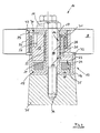
- eine erfindungsgemäße Steuereinrichtung des Reibradgetriebes in Schnittdarstellung mit nicht aktiviertem Servomotor zum ständigen Reibradeingriff,
- Fig.3
- die Steuereinrichtung mit aktiviertem Servomotor für unterbrochenem Reibradeingriff,
- Fig.4
- die Steuereinrichtung mit das Reibrad tragenden Schwenkarm in Explosionsdarstellung,
- Fig. 5
- eine Variante der Steuereinrichtung.
- Fig. 1
- a frictional wheel gear arranged co-operatively with a belt drive at an end side on an internal combustion engine shown in sections, for a separately arranged ancillary unit, in particular a coolant pump,
- Fig.2
- a control device according to the invention of the friction gear in a sectional view with non-activated servomotor for permanent Reibradeingriff,
- Figure 3
- the control device with activated servomotor for interrupted friction wheel engagement,
- Figure 4
- the control device with the friction wheel bearing arm in exploded view,
- Fig. 5
- a variant of the control device.
In einem Riementrieb 1 für nicht gezeigte Aggregate einer nur abschnittsweise dargestellten Brennkraftmaschine 2 ist ein Reibradgetriebe 3 vorgesehen für ein gesondert an der Brennkraftmaschine 2 angeordnetes Nebenaggregat 4 , das insbesondere eine Kühlmittelpumpe für den Kühlkreislauf der Brennkraftmaschine 2 ist.In a
Das Reibradgetriebe 3 umfasst ein in einem Umschlingungsbereich des Riemens 5 eines kurbelwellenseitigen Triebrades 6 der Brennkraftmaschine 2 mit der Außenseite 7 des Riemens 5 reibschlüssig zusammenwirkendes Reibrad 8 sowie ein mit dem Reibrad 8 reibschlüssig antreibbares Antriebsrad 9 der Kühlmittelpumpe 4. Das Reibrad 8 ist mittels einer Steuereinrichtung 10 insbesondere bei einem Kaltstart der Brennkraftmaschine 2 außer Eingriff mit dem pumpenseitigen Antriebsrad 9 gesteuert.The
Zur Erzielung einer konzeptionell bedingt ausfallsicheren Steuereinrichtung 10 steht das Reibrad 8 über einen Schwenkarm 11 mit einem in einer maschinenseitig fixierten Aufnahme 12 angeordneten Exzenter 13 in Verbindung, wobei der Exzenter 13 in der Aufnahme 12 über ein Steilgewinde 14 geführt angeordnet ist derart, dass eine aus der gegen einen Federwiderstand mittels eines Servomotors 15 bewirkten Hubbewegung des Exzenters 13 zwangsweise gekoppelte Drehbewegung des Exzenters 13 der Steuerung des mit dem Reibrad 8 verbundenen Schwenkarmes 11 für eine Ab - / Zuschaltung der Kühlmittelpumpe 4 dient.To achieve a conceptionally conditionally fail-
Eine kompakte und leichtgängige Steuereinrichtung 10 ist mit einer als topfartiges Gehäuse 16 gestalteten Aufnahme 12 erzielt mit einem zentrischen Rohrfortsatz 17 mit am Außenumfang angeordneten ersten Gewindegängen 18 für ein Kugelgewinde 19, wobei die in einem zylindrischen Käfig 20 gesicherten Gewindekugeln in am Innenumfang einer den Exzenter 13 durchsetzenden Durchbrechung 21 angeordnete zweite Gewindegänge 22 eingreifen.A compact and smooth-running
In weiterer Ausgestaltung ist der Exzenter 13 in dem Gehäuse 16 über einen Zentrierbund 23 drehgeführt angeordnet, und ferner ist zur Unterstützung einer kompakten Bauweise der freien Stirnfläche 24 des Zentrierbundes 23 gegenüber im Gehäuse 16 ein schaltbarer Elektromagnet 25 als Servomotor 15 angeordnet. In einem Auge 26 des Schwenkarmes 11 ist eine auf den Exzenter 13 derart treibend einwirkende Schraubendrehfeder 27 angeordnet, dass der Exzenter 13 über das Steilgewinde 14 bei unbestromtem Elektromagneten 25 zum einen zu diesem auf Hub- Distanz gehalten und zum anderen zugleich in eine das Reibrad 8 in Wirkeingriff mit dem Antriebsrad 9 der Kühlmittelpumpe 4 haltend Position gedreht ist.In a further embodiment, the eccentric 13 is rotatably guided in the
Eine der kompakten Bauweise der Steuereinrichtung 10 förderliche Anordnung sieht vor , dass die in dem Auge 26 des aus einem Kunststoff gebildeten Schwenkarmes 11 gegen einen Absatz 28 eines in dem Auge 26 zur Verstärkung angeordneten Metallgehäuses 29 einerseits anliegende Schraubendrehfeder 27 andererseits über einen in dem Metallgehäuse 29 mit Spiel zentrierten und mit dem Exzenter 13 über eine Verschraubung 30 verbundenen Deckel 31 axialgesichert gehalten ist. Wie aus
Die vorbeschriebene Federanordnung ermöglicht eine hohe Betriebssicherheit dadurch, dass mittels der Schraubendrehfeder 27 über ihre Drehvorspannung bei stromlosen Elektromagneten 25 der Exzenter 13 über das Steilgewinde 14 in eine Position gedreht ist, mittels der das äquidistant zum Triebrad 6 auf der Riemenaußenseite 7 geführte Reibrad 8 unter Zugbelastung des Schwenkarmes 11 in reibschlüssigen Eingriff mit dem Antriebsrad 9 gebracht und gehalten ist. Bei Ausfall des Servomotors 15 bzw. des Elektromagneten 25 bleibt die Kühlmittelpumpe 4 somit in vorteilhafter Weise in Antriebsverbindung über das Reibradgetriebe 3 mit dem Riementrieb 1. Die erfindungsgemäß bevorzugte Zugbelastung des Schwenkarmes 11 für den reibschlüssigen Eingriff des Reibrades 8 mit dem Antriebsrad 9 erlaubt in vorteilhafter Weise einen leichtbauenden Schwenkarm 11.The above-described spring arrangement enables a high level of operational reliability in that by means of the
Demgegenüber ist bei bestromtem Elektromagneten 25 bzw. aktiviertem Servomotor 15 der Exzenter 13 über das Steilgewinde 14 in eine Gegenposition gedreht derart, dass das Reibrad 8 über den Schwenkarm 11 außer Eingriff mit dem Antriebsrad 9 gebracht und gehalten ist, wobei mittels der auf den Schwenkarm 11 über ihre Drehvorspannung einwirkende Schraubendrehfeder 27 das Reibrad 8 gegen die Riemenaußenseite 7 äquidistant im Umschlingungsbereich des Triebrades 6 geführt angedrückt ist zum reibschlüssigen Freilauf des Reibrades 8. Damit ist zum einen eine die reibschlüssige Mitnahme des Reibrades 8 störende Verschmutzung der Riemenaußenseite 7 unterbunden und zum anderen ist beim gesteuerten Eingriff des Reibrades 8 mit dem Antriebsrad 9 lediglich die Kühlmittelpumpe 4 einer Drehbeschleunigung ausgesetzt.In contrast, when
Im weiteren ist zur Kapselung des Auges 26 servomotorseitig ein mit dem Exzenter 13 drehfest verbundener Deckel 32 vorgesehen und andererseits ein auf dem Rohrfortsatz 17 stirnseitig aufliegender, drehfest gesicherter Abschlussdeckel 33 , wobei die gesamte Steuereinrichtung 10 einschließlich des das Reibrad 8 tragenden Schwenkarmes 11 mittels eines die Deckel 31 , 32 , 33 und den Rohrfortsatz 17 durchsetzenden Schraubbolzen 34 an einem maschinenseitigen Butzen 35 stirnseitig der Brennkraftmaschine 2 im freien Bereich zwischen Triebrad 6 und benachbartem Antriebsrad 9 der Kühlmittelpumpe 4 angeordnet ist. Diese vorteilhafte Platzausnutzung ist mit der erfindungsgemäß kleinbauenden Steuereinrichtung 10 erzielt.
Wie bereits weiter vorne ausgeführt, ist das Nebenaggregat 4 vorzugsweise eine der Brennkraftmaschine 2 dienende Kühlmittelpumpe, deren über die Mechanik der jeweiligen Steuereinrichtung 10 , 10' in Eingriff mit dem Kühlmittelpumpen - Antriebsrad 9 gesteuertes und in Eingriff gehaltenes Reibrad 8 bedarfsweise entweder durch einen Parameter der Brennkraftmaschine 2 oder durch ein Kennfeld einer Motronic angesteuerten Servomotor 15 außer Eingriff gebracht ist. Dies kann insbesondere bei Kaltstart der Brennkraftmaschine 2 sein, ferner ist es auch in deren Hochdrehzahlbereich denkbar, vorzugsweise in einer intermittierendem Zu - und Abschaltung .As already stated above, the
Claims (9)
- A unit belt drive of an internal combustion engine comprising a friction gear with a control device and a sub-unit,- wherein the friction gear (3) comprises a friction wheel (8) frictionally co-operating with the outside (7) of a belt drive in a loop region thereof, the belt (5) belonging to a drive wheel (6) of the internal combustion engine (2) or of another unit, and also comprises a driving wheel (9) frictionally drivable by the friction wheel (8) and belonging to the sub-unit (4), characterised in that- the friction wheel (8), via a control device (10, 10') is brought into and out of engagement with the belt (5) or the driving wheel (9) as required,- the friction wheel (8), via a swivel arm (11, 11'), is connected to an eccentric (13, 39) of the control device (10, 10') disposed in a receiver (12, 12') fixed to the engine, wherein- the eccentric (13, 39) is guided in the receiver (12, 12') by a quick-acting screw thread (14, 41), such that- automatically couples rotation of the eccentric (13, 39) of the control means of the swivel arm (11, 11') connected to the friction wheel (8), resulting from the reciprocating movement of the eccentric (13, 39) caused by a servomotor (15, 43) of the control device (10, 10') against spring resistance, is used for switching the sub-unit (4) off and on.
- A unit belt drive according to claim 1 , characterised in that- the receiver (12) is a pot-like casing (16) comprising a central tubular extension (17) with first screw threads (18) disposed on the outer periphery for a ball screw (19), wherein- the balls, secured in a cylindrical cage (20), engage in second screw threads (22) disposed on the inner periphery of an aperture (21) through the eccentric (13).
- A unit belt drive according to claim 2, characterised in that- the eccentric (13) is guided in rotation in the casing (16) via a centring collar (23) and- a servomotor (15) in the form of a switchable electromagnet (25) is disposed in the casing (16) opposite the free end face (24) of the centring collar (23), wherein- the eccentric (13), relative to the electromagnet (25) or servomotor (15) when not energised, is held at a distance by a helical torsion spring (27) acting on and driving the eccentric (13) in an eyelet (26) of the swivel arm (11).
- A unit belt drive according to claims 2 and 3, characterised in that- the helical torsion spring (27), which at one end abuts a heel (28) of a metal casing (29) disposed in the eyelet (26), in the eyelet (26) of the swivel arm (11), which is made of plastic,- is axially held and secured at the other end by a cover (31) connected by screws (30) to the eccentric (13) and centred with clearance in the middle casing (29) of the eyelet (26), wherein- the helical torsion spring (27), which is prestressed in rotation, is co-rotatably connected at one end to the eccentric (13) and at the other end to the eyelet (26) of the swivel arm (11).
- A unit belt drive according to claims 2 to 4, characterised in that- by means of the rotary prestress on the helical torsion spring (27) when the electromagnet (25) or servomotor (15) is not energised, the eccentric (13) is rotated by the quick-acting screwthread (14) into a position by means of which- the friction wheel (8), guided in equidistant manner relative to the respective drive wheel (6), is brought and held in frictional engagement with the driving wheel (9) under tensile loading by the swivel arm (11).
- A unit belt drive according to claims 2 to 5,
characterised in that when the electromagnet (25) is energised, the eccentric (13) is rotated by the quick-acting screwthread (14) into a matching position,- by means of which the friction wheel (8), via the swivel arm (11), is brought and held out of engagement with the driving wheel (9), wherein- by means of the helical torsion spring (27) acting on the swivel arm (11) via its rotational prestress, the friction wheel (8) is pressed and guided against the outer side (7) of the belt in equidistant manner in the looped region of the respective driving wheel (6) so that it can run freely under friction. - A unit belt drive according to claims 2 to 6,
characterised in that- a cover (32) co-rotatably connected to the eccentric (13) on the servomotor side is provided for encapsulating the eyelet (26) and- on the other side a co-rotatably secured closing cover (33) bears on the end face of the tubular extension (17), wherein- the entire control device is secured on a stub (35) of the invention by means of a screw bolt (34) extending through the covers (31, 32, 33) and the tubular extension (17). - A unit belt drive according to claim 1,
characterised in that- the receiver (12') is a pot-like casing (36) with a central tubular extension (38) through which a fastening bolt (37) extends, and- is disposed coaxially with a pressure spring (40) axially acting on the eccentric (39), wherein- the eccentric (13) via an interposed ball and quick-acting screwthread (41) between its outer periphery and the inner periphery of the outer wall (42) of the casing (36) is guided in rotation and reciprocation by a servomotor (43) in conjunction with the pressure spring (40). - A unit belt drive according to claims 2 to 8,
characterised in that- the sub-unit (4) is a coolant pump for the internal combustion engine (2),- wherein the friction wheel (8) is brought out of engagement with the driving wheel (9) by the servomotor (15), using a parameter of the engine (2) or a performance graph deposited in a motronic, wherein- the servomotor (15) is a switchable electromagnet (25).
Applications Claiming Priority (3)
| Application Number | Priority Date | Filing Date | Title |
|---|---|---|---|
| DE10255075 | 2002-11-26 | ||
| DE2002155075 DE10255075A1 (en) | 2002-11-26 | 2002-11-26 | In a belt drive for units of an internal combustion engine provided friction gear for a separate auxiliary unit |
| PCT/EP2003/011404 WO2004048808A1 (en) | 2002-11-26 | 2003-10-15 | Friction gear mechanism for a separate ancillary unit provided in a belt drive for units of an internal combustion engine |
Publications (2)
| Publication Number | Publication Date |
|---|---|
| EP1565671A1 EP1565671A1 (en) | 2005-08-24 |
| EP1565671B1 true EP1565671B1 (en) | 2010-02-24 |
Family
ID=32240429
Family Applications (1)
| Application Number | Title | Priority Date | Filing Date |
|---|---|---|---|
| EP03757980A Expired - Lifetime EP1565671B1 (en) | 2002-11-26 | 2003-10-15 | Accessories belt drive of an internal combustion engine |
Country Status (3)
| Country | Link |
|---|---|
| EP (1) | EP1565671B1 (en) |
| DE (2) | DE10255075A1 (en) |
| WO (1) | WO2004048808A1 (en) |
Families Citing this family (15)
| Publication number | Priority date | Publication date | Assignee | Title |
|---|---|---|---|---|
| DE10255079A1 (en) * | 2002-11-26 | 2004-06-03 | Bayerische Motoren Werke Ag | A friction gear for a separate auxiliary unit assigned to an aggregate belt drive of an internal combustion engine |
| DE10309062A1 (en) | 2003-03-03 | 2004-09-16 | Bayerische Motoren Werke Ag | Friction wheel of a friction wheel transmission for an auxiliary unit arranged separately from an aggregate belt drive of an internal combustion engine |
| DE10309061A1 (en) | 2003-03-03 | 2004-10-14 | Bayerische Motoren Werke Ag | Friction gear for a separately arranged auxiliary unit interacting with a belt drive of an internal combustion engine |
| EP1464870B1 (en) * | 2003-04-02 | 2012-08-29 | DAYCO EUROPE S.r.l. | Drive assembly for driving a rotary member, in particular a combustion engine water pump shaft |
| ITTO20030441A1 (en) * | 2003-06-12 | 2004-12-13 | Dayco Europe Srl | CLUTCH WHEEL TRANSMISSION DEVICE. |
| DE10330672B4 (en) * | 2003-07-08 | 2006-10-12 | Bayerische Motoren Werke Ag | Belt drive for auxiliary equipment of an internal combustion engine |
| DE10346426A1 (en) * | 2003-10-07 | 2005-05-19 | Bayerische Motoren Werke Ag | Swivel arm arrangement for a friction gear of an accessory of an equipped with belt-driven auxiliary equipment internal combustion engine |
| DE10346425A1 (en) | 2003-10-07 | 2005-05-19 | Bayerische Motoren Werke Ag | Friction gear for a separate accessory of equipped with belt-driven auxiliary equipment internal combustion engine |
| DE602005021197D1 (en) * | 2005-02-28 | 2010-06-24 | Dayco Europe Srl | Reibradaktuator |
| FR2884886B1 (en) | 2005-04-21 | 2009-04-17 | Renault Sas | DEVICE FOR FRICTION DRIVING AN INTERNAL COMBUSTION ENGINE ACCESSORY |
| US9334932B2 (en) | 2011-05-13 | 2016-05-10 | Litens Automotive Partnership | Intelligent belt drive system and method |
| US9464697B2 (en) | 2011-09-05 | 2016-10-11 | Litens Automotive Partnership | Intelligent belt drive system and method |
| US9447850B2 (en) | 2012-04-28 | 2016-09-20 | Litens Automotive Partnership | Adjustable tensioner |
| WO2016199186A1 (en) * | 2015-06-08 | 2016-12-15 | 日産自動車株式会社 | Accessory driving device for vehicle |
| JP6344529B2 (en) * | 2015-06-22 | 2018-06-20 | 日産自動車株式会社 | Auxiliary drive device for vehicle |
Family Cites Families (10)
| Publication number | Priority date | Publication date | Assignee | Title |
|---|---|---|---|---|
| US1391572A (en) * | 1919-01-24 | 1921-09-20 | Thomas B Nickel | Pump-operating mechanism |
| GB461603A (en) * | 1936-07-20 | 1937-02-19 | Karl Metzger | Improvements in or relating to air-conditioning systems in motor vehicles |
| US2823546A (en) * | 1952-06-27 | 1958-02-18 | Barrett Walter William Henry | Coupling for the transmission of rotary motion |
| CH492247A (en) * | 1967-12-27 | 1970-02-27 | Piquerez Sa Ervin | Waterproof watch box |
| DE3225388A1 (en) * | 1982-07-07 | 1984-01-12 | Robert Bosch Gmbh, 7000 Stuttgart | Device for driving auxiliary units of motor vehicles |
| US4822321A (en) * | 1988-07-18 | 1989-04-18 | General Motors Corporation | Combination water pump and belt tensioner |
| DE3934884A1 (en) | 1989-10-19 | 1991-04-25 | Bayerische Motoren Werke Ag | Auxiliary drive mechanism for IC engine - incorporates tension wheel pressing against belt and driving shaft |
| DE4039206A1 (en) * | 1990-12-08 | 1992-06-11 | Audi Ag | Drive mechanism with first and second drive pieces - has continuous belts ,one toothed and one flat, with drive and driven wheels |
| DE19727914A1 (en) * | 1997-07-01 | 1999-01-07 | Bayerische Motoren Werke Ag | Slip clutch for a drivable unit, in particular an auxiliary unit of an internal combustion engine |
| DE10236746A1 (en) | 2002-08-10 | 2004-02-19 | Bayerische Motoren Werke Ag | Internal combustion engine with a drive arrangement for unit modules |
-
2002
- 2002-11-26 DE DE2002155075 patent/DE10255075A1/en not_active Ceased
-
2003
- 2003-10-15 DE DE50312456T patent/DE50312456D1/en not_active Expired - Lifetime
- 2003-10-15 EP EP03757980A patent/EP1565671B1/en not_active Expired - Lifetime
- 2003-10-15 WO PCT/EP2003/011404 patent/WO2004048808A1/en not_active Ceased
Also Published As
| Publication number | Publication date |
|---|---|
| EP1565671A1 (en) | 2005-08-24 |
| DE10255075A1 (en) | 2004-06-03 |
| DE50312456D1 (en) | 2010-04-08 |
| WO2004048808A1 (en) | 2004-06-10 |
Similar Documents
| Publication | Publication Date | Title |
|---|---|---|
| EP1565671B1 (en) | Accessories belt drive of an internal combustion engine | |
| DE4315826C5 (en) | Motor-pump assembly | |
| DE4401074B4 (en) | Pump arrangement, in particular for conveying fuel from a reservoir to an internal combustion engine | |
| EP1414636B1 (en) | Electromechanical linear drive | |
| DE69800206T2 (en) | Heavy-duty viscous fan drive and holding device therefor | |
| DE10311037B4 (en) | Electric oil pump device | |
| EP1188003A1 (en) | Tensioning device for traction means such as belts or chains | |
| EP0855515A1 (en) | Pump, especially adjustable coolant pump, for motor vehicles | |
| DE3503471A1 (en) | FLOW RATE CONTROL DEVICE FOR A COOLANT COMPRESSOR WITH FLOW RATE ADJUSTMENT DEVICE | |
| DE69717244T2 (en) | Pump device for supplying fuel from a tank to an internal combustion engine | |
| DE102021125611A1 (en) | Electromechanical actuation actuator and method for operating an electromechanical actuation actuator | |
| DE102005047203A1 (en) | Internal combustion engine with variable compression ratio | |
| DE202022002768U1 (en) | Electromechanical actuating actuator | |
| WO2004048759A1 (en) | Belt drive for auxiliary units in an internal combustion engine | |
| EP1381744B1 (en) | Locking cylinder | |
| DE10309063A1 (en) | Friction gear for an auxiliary unit arranged separately from an assembly belt drive of an internal combustion engine | |
| DE202008011202U1 (en) | Reibschaltkupplung with one of a drive motor via a drive belt driven drive wheel and drive unit | |
| EP1671050B1 (en) | Articulated-arm assembly for a friction gear of a secondary assembly in an internal combustion engine that is equipped with belt-driven auxiliary assemblies | |
| EP1565672B1 (en) | Accessories belt drive of an internal combustion engine | |
| EP3077676A1 (en) | Variable pump for an internal combustion engine | |
| EP1455064B1 (en) | Belt drive for engine accessories with a friction wheel drive with a controller and a accessory | |
| DE29716110U1 (en) | Magnetic clutch pump | |
| DE69000833T2 (en) | DEVICE FOR ADJUSTING THE STROKE OF A FUEL INJECTION PUMP. | |
| DE19843120C1 (en) | Adjustable radial piston pump or motor | |
| WO2013056855A1 (en) | Adjustable coolant pump |
Legal Events
| Date | Code | Title | Description |
|---|---|---|---|
| PUAI | Public reference made under article 153(3) epc to a published international application that has entered the european phase |
Free format text: ORIGINAL CODE: 0009012 |
|
| 17P | Request for examination filed |
Effective date: 20050211 |
|
| AK | Designated contracting states |
Kind code of ref document: A1 Designated state(s): AT BE BG CH CY CZ DE DK EE ES FI FR GB GR HU IE IT LI LU MC NL PT RO SE SI SK TR |
|
| RBV | Designated contracting states (corrected) |
Designated state(s): DE ES FR GB IT |
|
| 17Q | First examination report despatched |
Effective date: 20080320 |
|
| RTI1 | Title (correction) |
Free format text: ACCESSORIES BELT DRIVE OF AN INTERNAL COMBUSTION ENGINE |
|
| GRAP | Despatch of communication of intention to grant a patent |
Free format text: ORIGINAL CODE: EPIDOSNIGR1 |
|
| RTI1 | Title (correction) |
Free format text: ACCESSORIES BELT DRIVE OF AN INTERNAL COMBUSTION ENGINE |
|
| GRAS | Grant fee paid |
Free format text: ORIGINAL CODE: EPIDOSNIGR3 |
|
| GRAA | (expected) grant |
Free format text: ORIGINAL CODE: 0009210 |
|
| AK | Designated contracting states |
Kind code of ref document: B1 Designated state(s): DE ES FR GB IT |
|
| REG | Reference to a national code |
Ref country code: GB Ref legal event code: FG4D Free format text: NOT ENGLISH |
|
| REF | Corresponds to: |
Ref document number: 50312456 Country of ref document: DE Date of ref document: 20100408 Kind code of ref document: P |
|
| PG25 | Lapsed in a contracting state [announced via postgrant information from national office to epo] |
Ref country code: ES Free format text: LAPSE BECAUSE OF FAILURE TO SUBMIT A TRANSLATION OF THE DESCRIPTION OR TO PAY THE FEE WITHIN THE PRESCRIBED TIME-LIMIT Effective date: 20100604 |
|
| PLBE | No opposition filed within time limit |
Free format text: ORIGINAL CODE: 0009261 |
|
| STAA | Information on the status of an ep patent application or granted ep patent |
Free format text: STATUS: NO OPPOSITION FILED WITHIN TIME LIMIT |
|
| 26N | No opposition filed |
Effective date: 20101125 |
|
| PG25 | Lapsed in a contracting state [announced via postgrant information from national office to epo] |
Ref country code: IT Free format text: LAPSE BECAUSE OF FAILURE TO SUBMIT A TRANSLATION OF THE DESCRIPTION OR TO PAY THE FEE WITHIN THE PRESCRIBED TIME-LIMIT Effective date: 20100224 |
|
| REG | Reference to a national code |
Ref country code: FR Ref legal event code: PLFP Year of fee payment: 13 |
|
| REG | Reference to a national code |
Ref country code: FR Ref legal event code: PLFP Year of fee payment: 14 |
|
| REG | Reference to a national code |
Ref country code: FR Ref legal event code: PLFP Year of fee payment: 15 |
|
| REG | Reference to a national code |
Ref country code: FR Ref legal event code: PLFP Year of fee payment: 16 |
|
| PGFP | Annual fee paid to national office [announced via postgrant information from national office to epo] |
Ref country code: FR Payment date: 20221020 Year of fee payment: 20 |
|
| PGFP | Annual fee paid to national office [announced via postgrant information from national office to epo] |
Ref country code: GB Payment date: 20221024 Year of fee payment: 20 Ref country code: DE Payment date: 20220621 Year of fee payment: 20 |
|
| P01 | Opt-out of the competence of the unified patent court (upc) registered |
Effective date: 20230502 |
|
| REG | Reference to a national code |
Ref country code: DE Ref legal event code: R071 Ref document number: 50312456 Country of ref document: DE |
|
| REG | Reference to a national code |
Ref country code: GB Ref legal event code: PE20 Expiry date: 20231014 |
|
| PG25 | Lapsed in a contracting state [announced via postgrant information from national office to epo] |
Ref country code: GB Free format text: LAPSE BECAUSE OF EXPIRATION OF PROTECTION Effective date: 20231014 |
|
| PG25 | Lapsed in a contracting state [announced via postgrant information from national office to epo] |
Ref country code: GB Free format text: LAPSE BECAUSE OF EXPIRATION OF PROTECTION Effective date: 20231014 |