EP1599658B1 - Soupape d'echange des gaz d'un moteur a combustion - Google Patents
Soupape d'echange des gaz d'un moteur a combustion Download PDFInfo
- Publication number
- EP1599658B1 EP1599658B1 EP05706738A EP05706738A EP1599658B1 EP 1599658 B1 EP1599658 B1 EP 1599658B1 EP 05706738 A EP05706738 A EP 05706738A EP 05706738 A EP05706738 A EP 05706738A EP 1599658 B1 EP1599658 B1 EP 1599658B1
- Authority
- EP
- European Patent Office
- Prior art keywords
- valve
- keeper
- cone
- stem
- hand
- Prior art date
- Legal status (The legal status is an assumption and is not a legal conclusion. Google has not performed a legal analysis and makes no representation as to the accuracy of the status listed.)
- Expired - Fee Related
Links
Images

Classifications
-
- F—MECHANICAL ENGINEERING; LIGHTING; HEATING; WEAPONS; BLASTING
- F01—MACHINES OR ENGINES IN GENERAL; ENGINE PLANTS IN GENERAL; STEAM ENGINES
- F01L—CYCLICALLY OPERATING VALVES FOR MACHINES OR ENGINES
- F01L3/00—Lift-valve, i.e. cut-off apparatus with closure members having at least a component of their opening and closing motion perpendicular to the closing faces; Parts or accessories thereof
- F01L3/20—Shapes or constructions of valve members, not provided for in preceding subgroups of this group
-
- F—MECHANICAL ENGINEERING; LIGHTING; HEATING; WEAPONS; BLASTING
- F01—MACHINES OR ENGINES IN GENERAL; ENGINE PLANTS IN GENERAL; STEAM ENGINES
- F01L—CYCLICALLY OPERATING VALVES FOR MACHINES OR ENGINES
- F01L2303/00—Manufacturing of components used in valve arrangements
Definitions
- the invention relates to a gas exchange valve of an internal combustion engine according to the preamble of patent claim 1.
- Such gas exchange valves are known, for example, from WO99 / 16295 and US 2,398,514.
- the invention is concerned with the problem of minimizing the stresses on the valve disk, in particular in its bottom region, due to temperature and combustion chamber pressure by means of an optimized disk geometry, in particular in its bottom area, while at the same time having as small a wall thickness as possible.
- the overall deformation of the valve should be taken into account, with regard to a displacement of the valve stem on the one hand and to the deformation of the valve bottom between the support in the bottom center and the outer bottom region under combustion chamber pressure on the other.
- the invention is based on the general idea of reinforcing the valve bottom in the case of an overall convex outward shape by means of annular bead regions surrounding the valve axis, each having a convexly outwardly extending bead cross section.
- annular bead which may also be referred to as a torus section
- a plurality of annular beads arranged concentrically with one another within the valve base can also be provided.
- the central portion of the valve bottom when adjacent to a hollow valve stem, may be outwardly convex or concave.
- the individual elements of the gas exchange valve according to the invention are usually welded together in an embodiment of the valve made of metal.
- valve cone which is generally used in practice, "cone” with respect to its shape is not strictly mathematical, but rather to be understood in the sense of an arbitrary funnel shape.
- the valve bottom closes via a connection collar to the valve cone at.
- the connection is made such that the radially outer edge regions of the valve bottom in the form of the connection collar on the one hand and the valve cone on the other hand in a conical surface formed by the lateral surface of a fictitious, erected in the valve axis cone with a reference to the valve cone tapered connection surface and in this conical surface together in the direction of the cone base surface leak.
- valve disc made of metal are welded together without the welds are shown as such.
- the valve disk according to the invention according to FIG. 1 comprises a valve bottom 1, a hollow valve cone 2 and a hollow valve stem 3.
- the valve base 1 is welded to the hollow cylindrical seated valve stem 3 on the one hand and the outer edge of the valve cone 2 on the other.
- the tapered end of the valve cone 2 is welded to the valve stem 3.
- the interconnected, aforementioned components together form a rigid rotating surface supporting structure.
- the valve bottom 1 has a largely flat central area 4 in the middle of the floor.
- the annular region lying between this central region 4 and the outer edge of the valve base 1 is designed as an annular bead 5, which can also be referred to as a torus section, with an outwardly convex curvature.
- connection collar 7 is additionally formed between the annular bead 5 and a radially outer joining region 6 between the valve bottom 1 and the valve plug 2.
- connection collar 7 adjoins the valve cone 2 in a connection surface which is formed on a cone erected in the valve axis by a lateral surface of a fictitious cone with a constriction which is rectilinear with respect to the valve cone 2.
- the connection collar 7 and the adjacent edge region of the valve cone 2 run together in this conical surface in the direction of the cone base surface.
- valve stem 3 with a widened area 8 inside the valve is used in a departure from the embodiment according to FIG. Through this widened region 8 improved support of the valve bottom 1 is achieved in its central region.
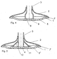
- valve embodiment according to FIG. 4 differs from that according to FIG. 3 only in that the valve bottom 1 is convexly curved in a central region 9 outwardly within the widened region 8 of the valve stem 3 to the outside.
- FIG. 5 is based on a basic valve shape according to FIG. 2.
- a support cone 10 is provided in the interior of the valve cone 2. In its tapered region of this support cone 10 is welded to the valve stem 3. At the valve bottom 1 of the support cone 10 is also welded.
- the valve bottom with two concentric annular beads 5 ', 11 has a particularly good stability.
Landscapes
- Engineering & Computer Science (AREA)
- Physics & Mathematics (AREA)
- Geometry (AREA)
- Mechanical Engineering (AREA)
- General Engineering & Computer Science (AREA)
- Lift Valve (AREA)
Claims (9)
- Soupape de renouvellement des gaz d'un moteur à combustion interne comportant respectivement une tige de soupape en particulier creuse (3) et une tête de soupape, dans laquelle- la tête de soupape comprend un plateau de soupape (1) et un cône de soupape creux (2) relié au bord extérieur de celle-ci, le cône de soupape (2) rétrécissant au fur et à mesure de l'éloignement par rapport au plateau,- la tige de soupape (3) traverse le cône de soupape creux (2) et est respectivement reliée fermement d'une part au plateau de soupape (1) ainsi que d'autre part à l'extrémité étroite du cône de soupape(2),- l'extrémité de la tige de soupape (3) reliée au plateau de soupape (1) fait saillie au-delà du plan de liaison entre le cône de soupape (2) et le plateau de soupape (1),caractérisée en ce
que le plateau de soupape (1) comporte dans la zone annulaire située entre son rattachement à la tige de soupape (3) d'une part et le cône de soupape (2) d'autre part, au moins une moulure annulaire (5 ; 5', 11) adjacente radialement, présentant une surface de section transversale de moulure annulaire s'étendant de manière convexe vers l'extérieur. - Soupape de renouvellement des gaz selon la revendication 1 ou 2,
caractérisée en ce
que la tige de soupape (3) possède un diamètre plus grand à son extrémité reliée au plateau de soupape (1) qu'à sa zone de liaison avec le cône de soupape (2). - Soupape de renouvellement des gaz selon l'une des revendications précédentes, comportant une tige de soupape cylindrique creuse, reposant de manière ouverte sur le plateau de soupape (9),
caractérisée en ce
que le plateau de soupape (1) est courbé de manière convexe vers l'extérieur à l'intérieur de sa zone adjacente à l'espace creux de la tige de soupape (3). - Soupape de renouvellement des gaz selon la revendication 1 ou 2,
caractérisée en ce
que le plateau de soupape (1) est courbé de manière concave de l'extérieur vers l'intérieur à l'intérieur de sa zone adjacente à l'espace creux de la tige de soupape (3). - Soupape de renouvellement des gaz selon l'une des revendications précédentes,
caractérisée en ce
qu'à l'intérieur du cône de soupape (2) est prévu un cône d'appui (10) intérieur avec une liaison d'une part au plateau de soupape (1), dans une zone entre deux moulures (5', 11) adjacentes l'une à l'autre radialement et d'autre part à la tige de soupape (3) dans sa zone étroite. - Soupape de renouvellement des gaz selon l'une des revendications précédentes,
caractérisée en ce
que les moulures annulaires (5 ; 5', 11) présentent un profil de section transversale réalisé suivant une forme parabolique, hyperbolique ou logarithmique. - Soupape de renouvellement des gaz d'un moteur à combustion interne comportant respectivement une tige de soupape (3) et une tête de soupape, dans laquelle- la tête de soupape comprend un plateau de soupape (1) et un cône de soupape creux (2) relié au bord extérieur de celle-ci, le cône de soupape (2) rétrécissant au fur et à mesure de l'éloignement par rapport au plateau de soupape (1),- la tige de soupape (3) traverse le cône de soupape creux (2) et est respectivement reliée fermement d'une part au plateau de soupape (1) ainsi que d'autre part à l'extrémité étroite du cône de soupape (2), selon en particulier l'une des revendications précédentescaractérisée en ce
que les zones marginales radialement extérieures du plateau de soupape (1) se situent sous la forme d'une collerette de raccordement (7) d'une part ainsi que du cône de soupape (2) d'autre part, dans une surface de liaison formée par la génératrice d'un cône fictif dressé dans l'axe de la soupape comportant un rétrécissement orienté dans la même direction que le cône de soupape (2), et s'étendent ensemble dans cette surface conique en direction de la surface de la base du cône. - Soupape de renouvellement des gaz selon la revendication 7,
caractérisée en ce
que l'angle de cône du cône imaginé par la surface de génératrice mesure par rapport à sa surface de base 180°- α, où α = 15° à 45°. - Soupape de renouvellement des gaz selon la revendication 8,
caractérisée en ce
que l'angle α est compris entre 15° et 35°.
Applications Claiming Priority (3)
| Application Number | Priority Date | Filing Date | Title |
|---|---|---|---|
| DE102004010309 | 2004-03-03 | ||
| DE102004010309A DE102004010309A1 (de) | 2004-03-03 | 2004-03-03 | Gaswechselventil eines Verbrennungsmotors |
| PCT/DE2005/000179 WO2005085605A1 (fr) | 2004-03-03 | 2005-02-04 | Soupape d'echange des gaz d'un moteur a combustion |
Publications (2)
| Publication Number | Publication Date |
|---|---|
| EP1599658A1 EP1599658A1 (fr) | 2005-11-30 |
| EP1599658B1 true EP1599658B1 (fr) | 2006-05-17 |
Family
ID=34877288
Family Applications (1)
| Application Number | Title | Priority Date | Filing Date |
|---|---|---|---|
| EP05706738A Expired - Fee Related EP1599658B1 (fr) | 2004-03-03 | 2005-02-04 | Soupape d'echange des gaz d'un moteur a combustion |
Country Status (4)
| Country | Link |
|---|---|
| EP (1) | EP1599658B1 (fr) |
| JP (1) | JP4708413B2 (fr) |
| DE (2) | DE102004010309A1 (fr) |
| WO (1) | WO2005085605A1 (fr) |
Cited By (1)
| Publication number | Priority date | Publication date | Assignee | Title |
|---|---|---|---|---|
| DE102006061128B4 (de) * | 2006-12-22 | 2015-06-11 | Mahle International Gmbh | Gaswechselventil eines Verbrennungsmotors |
Families Citing this family (6)
| Publication number | Priority date | Publication date | Assignee | Title |
|---|---|---|---|---|
| DE102006061127B4 (de) * | 2006-12-22 | 2016-07-14 | Mahle International Gmbh | Metallisches Leichtbauventil eines Verbrennungsmotors |
| WO2014155667A1 (fr) * | 2013-03-29 | 2014-10-02 | 日鍛バルブ株式会社 | Soupape champignon creuse |
| DE102013210900A1 (de) * | 2013-06-11 | 2014-12-11 | Mahle International Gmbh | Gaswechselventil einer Brennkraftmaschine |
| DE102013210899A1 (de) | 2013-06-11 | 2014-12-11 | Mahle International Gmbh | Verfahren zur Herstellung eines gebauten Hohlventils |
| DE102016207799A1 (de) * | 2016-05-04 | 2017-11-09 | Mahle International Gmbh | Gaswechselventil für eine Brennkraftmaschine |
| DE102017119887A1 (de) * | 2017-08-30 | 2019-02-28 | Man Truck & Bus Ag | Ventil für einen Verbrennungsmotor |
Family Cites Families (12)
| Publication number | Priority date | Publication date | Assignee | Title |
|---|---|---|---|---|
| US1727621A (en) * | 1928-02-18 | 1929-09-10 | Gen Motors Corp | Exhaust valve |
| GB471605A (en) * | 1935-08-17 | 1937-09-08 | Teves Kg Alfred | Improvements in or relating to hollow poppet valves |
| US2371548A (en) * | 1943-12-06 | 1945-03-13 | Thomas F Saffady | Valve |
| US4164957A (en) * | 1977-11-23 | 1979-08-21 | Caterpillar Tractor Co. | Oil-cooled engine valve |
| DE3625590A1 (de) * | 1986-07-29 | 1988-02-04 | Odilo Schwaiger | Ventile fuer brennkraftmaschinen |
| SE467267B (sv) * | 1988-11-15 | 1992-06-22 | Volvo Ab | Ventil foer en foerbraenningsmotor |
| DE19705621A1 (de) * | 1997-02-14 | 1998-08-20 | Heinz Leiber | Gaswechselventil und Verfahren zum Messen des Druckes in einem Brennraum einer Brennkraftmaschine |
| EP0898055B1 (fr) * | 1997-08-19 | 2002-05-08 | TRW Deutschland GmbH | Soupape creuse pour moteur à combustion interne |
| DE19804053A1 (de) * | 1998-02-03 | 1999-08-05 | Mwp Mahle J Wizemann Pleuco Gm | Leichtbauventil |
| WO2003056142A1 (fr) * | 2001-12-27 | 2003-07-10 | Mahle Ventiltrieb Gmbh | Soupape d'echange de gaz de moteur a combustion interne pourvue d'une tete creuse |
| DE10204122C1 (de) * | 2002-02-01 | 2003-05-08 | Daimler Chrysler Ag | Gebautes Ventil für Hubkolbenmaschinen und Verfahren zu dessen Herstellung |
| DE10217719A1 (de) * | 2002-04-20 | 2003-11-06 | Mahle Ventiltrieb Gmbh | Beweglicher, heißen Gasen ausgesetzter Verschlusskörper eines Ventiles |
-
2004
- 2004-03-03 DE DE102004010309A patent/DE102004010309A1/de not_active Withdrawn
-
2005
- 2005-02-04 EP EP05706738A patent/EP1599658B1/fr not_active Expired - Fee Related
- 2005-02-04 WO PCT/DE2005/000179 patent/WO2005085605A1/fr active IP Right Grant
- 2005-02-04 DE DE502005000011T patent/DE502005000011D1/de active Active
- 2005-02-04 JP JP2007501103A patent/JP4708413B2/ja not_active Expired - Fee Related
Cited By (1)
| Publication number | Priority date | Publication date | Assignee | Title |
|---|---|---|---|---|
| DE102006061128B4 (de) * | 2006-12-22 | 2015-06-11 | Mahle International Gmbh | Gaswechselventil eines Verbrennungsmotors |
Also Published As
| Publication number | Publication date |
|---|---|
| EP1599658A1 (fr) | 2005-11-30 |
| DE102004010309A1 (de) | 2005-09-22 |
| DE502005000011D1 (de) | 2006-06-22 |
| WO2005085605A1 (fr) | 2005-09-15 |
| JP2007526419A (ja) | 2007-09-13 |
| JP4708413B2 (ja) | 2011-06-22 |
Similar Documents
| Publication | Publication Date | Title |
|---|---|---|
| EP1599658B1 (fr) | Soupape d'echange des gaz d'un moteur a combustion | |
| EP1483493B1 (fr) | Piston refroidi constitue de plusieurs pieces concu pour un moteur a combustion interne | |
| DE60201518T2 (de) | Gewindeelement für eine ermüdungsbeständige gewinde-rohrverbindung | |
| EP2027381B1 (fr) | Piston en plusieurs parties, refroidi, pour un moteur à combustion interne | |
| EP2729689A1 (fr) | Piston pour un moteur à combustion interne | |
| DE19801051A1 (de) | Verbindungskopf für eine Hochdruck-Metallrohrleitung und gemeinsame Schiene, an der die Rohrleitung verbunden werden soll | |
| DE102009003525A1 (de) | Brennkammerbrennstoffdüsenaufbau | |
| EP2321513B2 (fr) | Piston pour un moteur à combustion interne | |
| DE112016005765T5 (de) | Kolben für einen Verbrennungsmotor | |
| WO2010075959A1 (fr) | Piston d'une seule pièce en acier, à système de refroidissement multicomposant optimisé | |
| US20070040144A1 (en) | Gas exchange valve for an internal combustion engine | |
| DE202007018740U1 (de) | Doppelsitzventil | |
| EP3353392B1 (fr) | Soupape destinée à des moteurs à combustion interne, pourvue d'une aube directrice pour un agent de refroidissement | |
| EP3601791B1 (fr) | Segment bride pour un segment annulaire de tour en acier pour éolienne et procédé associé | |
| WO2017133947A1 (fr) | Piston d'un moteur à combustion interne | |
| DE1924462B2 (de) | Druckgefaess | |
| CN108678168A (zh) | 一种适用于铝合金空间网格结构的螺栓环节点 | |
| DE2326694A1 (de) | Lagerzapfen-drehkegelventil als schweisskonstruktion aus rohr und blechen | |
| EP3467236B1 (fr) | Tour d'éolienne, en particulier pour une éolienne | |
| EP1660769B1 (fr) | Piston en plusieurs parties destine a un moteur a combustion interne | |
| EP0118461A1 (fr) | Refroidisseur de cheminee pour l'extinction a sec de coke. | |
| US6426986B1 (en) | Forged nozzle shell course for a pressure vessel | |
| DE10354086B4 (de) | Leichtbauventil | |
| DE112022000971T5 (de) | Tellerventil | |
| EP0396952B1 (fr) | Raccord de tuyaux entre deux extrémités de tuyaux bout à bout pour les connecter ensemble |
Legal Events
| Date | Code | Title | Description |
|---|---|---|---|
| PUAI | Public reference made under article 153(3) epc to a published international application that has entered the european phase |
Free format text: ORIGINAL CODE: 0009012 |
|
| 17P | Request for examination filed |
Effective date: 20050630 |
|
| AK | Designated contracting states |
Kind code of ref document: A1 Designated state(s): AT BE BG CH CY CZ DE DK EE ES FI FR GB GR HU IE IS IT LI LT LU MC NL PL PT RO SE SI SK TR |
|
| AX | Request for extension of the european patent |
Extension state: AL BA HR LV MK YU |
|
| GRAP | Despatch of communication of intention to grant a patent |
Free format text: ORIGINAL CODE: EPIDOSNIGR1 |
|
| GRAS | Grant fee paid |
Free format text: ORIGINAL CODE: EPIDOSNIGR3 |
|
| GRAA | (expected) grant |
Free format text: ORIGINAL CODE: 0009210 |
|
| AK | Designated contracting states |
Kind code of ref document: B1 Designated state(s): DE FR GB |
|
| DAX | Request for extension of the european patent (deleted) | ||
| RBV | Designated contracting states (corrected) |
Designated state(s): DE FR GB |
|
| REG | Reference to a national code |
Ref country code: GB Ref legal event code: FG4D Free format text: NOT ENGLISH |
|
| REF | Corresponds to: |
Ref document number: 502005000011 Country of ref document: DE Date of ref document: 20060622 Kind code of ref document: P |
|
| GBT | Gb: translation of ep patent filed (gb section 77(6)(a)/1977) |
Effective date: 20060621 |
|
| RIN2 | Information on inventor provided after grant (corrected) |
Inventor name: ABELE, MARCUS Inventor name: LECHNER, MARTIN |
|
| ET | Fr: translation filed | ||
| PLBE | No opposition filed within time limit |
Free format text: ORIGINAL CODE: 0009261 |
|
| STAA | Information on the status of an ep patent application or granted ep patent |
Free format text: STATUS: NO OPPOSITION FILED WITHIN TIME LIMIT |
|
| 26N | No opposition filed |
Effective date: 20070220 |
|
| REG | Reference to a national code |
Ref country code: FR Ref legal event code: PLFP Year of fee payment: 12 |
|
| REG | Reference to a national code |
Ref country code: FR Ref legal event code: PLFP Year of fee payment: 13 |
|
| REG | Reference to a national code |
Ref country code: DE Ref legal event code: R084 Ref document number: 502005000011 Country of ref document: DE |
|
| REG | Reference to a national code |
Ref country code: FR Ref legal event code: PLFP Year of fee payment: 14 |
|
| PGFP | Annual fee paid to national office [announced via postgrant information from national office to epo] |
Ref country code: GB Payment date: 20180227 Year of fee payment: 14 |
|
| PGFP | Annual fee paid to national office [announced via postgrant information from national office to epo] |
Ref country code: FR Payment date: 20180227 Year of fee payment: 14 |
|
| PGFP | Annual fee paid to national office [announced via postgrant information from national office to epo] |
Ref country code: DE Payment date: 20180430 Year of fee payment: 14 |
|
| REG | Reference to a national code |
Ref country code: DE Ref legal event code: R119 Ref document number: 502005000011 Country of ref document: DE |
|
| GBPC | Gb: european patent ceased through non-payment of renewal fee |
Effective date: 20190204 |
|
| PG25 | Lapsed in a contracting state [announced via postgrant information from national office to epo] |
Ref country code: DE Free format text: LAPSE BECAUSE OF NON-PAYMENT OF DUE FEES Effective date: 20190903 Ref country code: GB Free format text: LAPSE BECAUSE OF NON-PAYMENT OF DUE FEES Effective date: 20190204 |
|
| PG25 | Lapsed in a contracting state [announced via postgrant information from national office to epo] |
Ref country code: FR Free format text: LAPSE BECAUSE OF NON-PAYMENT OF DUE FEES Effective date: 20190228 |