EP1599658B1 - Gas exchange valve for an internal combustion engine - Google Patents
Gas exchange valve for an internal combustion engine Download PDFInfo
- Publication number
- EP1599658B1 EP1599658B1 EP05706738A EP05706738A EP1599658B1 EP 1599658 B1 EP1599658 B1 EP 1599658B1 EP 05706738 A EP05706738 A EP 05706738A EP 05706738 A EP05706738 A EP 05706738A EP 1599658 B1 EP1599658 B1 EP 1599658B1
- Authority
- EP
- European Patent Office
- Prior art keywords
- valve
- keeper
- cone
- stem
- hand
- Prior art date
- Legal status (The legal status is an assumption and is not a legal conclusion. Google has not performed a legal analysis and makes no representation as to the accuracy of the status listed.)
- Expired - Fee Related
Links
Images

Classifications
-
- F—MECHANICAL ENGINEERING; LIGHTING; HEATING; WEAPONS; BLASTING
- F01—MACHINES OR ENGINES IN GENERAL; ENGINE PLANTS IN GENERAL; STEAM ENGINES
- F01L—CYCLICALLY OPERATING VALVES FOR MACHINES OR ENGINES
- F01L3/00—Lift-valve, i.e. cut-off apparatus with closure members having at least a component of their opening and closing motion perpendicular to the closing faces; Parts or accessories thereof
- F01L3/20—Shapes or constructions of valve members, not provided for in preceding subgroups of this group
-
- F—MECHANICAL ENGINEERING; LIGHTING; HEATING; WEAPONS; BLASTING
- F01—MACHINES OR ENGINES IN GENERAL; ENGINE PLANTS IN GENERAL; STEAM ENGINES
- F01L—CYCLICALLY OPERATING VALVES FOR MACHINES OR ENGINES
- F01L2303/00—Manufacturing of components used in valve arrangements
Definitions
- the invention relates to a gas exchange valve of an internal combustion engine according to the preamble of patent claim 1.
- Such gas exchange valves are known, for example, from WO99 / 16295 and US 2,398,514.
- the invention is concerned with the problem of minimizing the stresses on the valve disk, in particular in its bottom region, due to temperature and combustion chamber pressure by means of an optimized disk geometry, in particular in its bottom area, while at the same time having as small a wall thickness as possible.
- the overall deformation of the valve should be taken into account, with regard to a displacement of the valve stem on the one hand and to the deformation of the valve bottom between the support in the bottom center and the outer bottom region under combustion chamber pressure on the other.
- the invention is based on the general idea of reinforcing the valve bottom in the case of an overall convex outward shape by means of annular bead regions surrounding the valve axis, each having a convexly outwardly extending bead cross section.
- annular bead which may also be referred to as a torus section
- a plurality of annular beads arranged concentrically with one another within the valve base can also be provided.
- the central portion of the valve bottom when adjacent to a hollow valve stem, may be outwardly convex or concave.
- the individual elements of the gas exchange valve according to the invention are usually welded together in an embodiment of the valve made of metal.
- valve cone which is generally used in practice, "cone” with respect to its shape is not strictly mathematical, but rather to be understood in the sense of an arbitrary funnel shape.
- the valve bottom closes via a connection collar to the valve cone at.
- the connection is made such that the radially outer edge regions of the valve bottom in the form of the connection collar on the one hand and the valve cone on the other hand in a conical surface formed by the lateral surface of a fictitious, erected in the valve axis cone with a reference to the valve cone tapered connection surface and in this conical surface together in the direction of the cone base surface leak.
- valve disc made of metal are welded together without the welds are shown as such.
- the valve disk according to the invention according to FIG. 1 comprises a valve bottom 1, a hollow valve cone 2 and a hollow valve stem 3.
- the valve base 1 is welded to the hollow cylindrical seated valve stem 3 on the one hand and the outer edge of the valve cone 2 on the other.
- the tapered end of the valve cone 2 is welded to the valve stem 3.
- the interconnected, aforementioned components together form a rigid rotating surface supporting structure.
- the valve bottom 1 has a largely flat central area 4 in the middle of the floor.
- the annular region lying between this central region 4 and the outer edge of the valve base 1 is designed as an annular bead 5, which can also be referred to as a torus section, with an outwardly convex curvature.
- connection collar 7 is additionally formed between the annular bead 5 and a radially outer joining region 6 between the valve bottom 1 and the valve plug 2.
- connection collar 7 adjoins the valve cone 2 in a connection surface which is formed on a cone erected in the valve axis by a lateral surface of a fictitious cone with a constriction which is rectilinear with respect to the valve cone 2.
- the connection collar 7 and the adjacent edge region of the valve cone 2 run together in this conical surface in the direction of the cone base surface.
- valve stem 3 with a widened area 8 inside the valve is used in a departure from the embodiment according to FIG. Through this widened region 8 improved support of the valve bottom 1 is achieved in its central region.
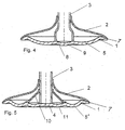
- valve embodiment according to FIG. 4 differs from that according to FIG. 3 only in that the valve bottom 1 is convexly curved in a central region 9 outwardly within the widened region 8 of the valve stem 3 to the outside.
- FIG. 5 is based on a basic valve shape according to FIG. 2.
- a support cone 10 is provided in the interior of the valve cone 2. In its tapered region of this support cone 10 is welded to the valve stem 3. At the valve bottom 1 of the support cone 10 is also welded.
- the valve bottom with two concentric annular beads 5 ', 11 has a particularly good stability.
Description
Die Erfindung betrifft ein Gaswechselventil eines Verbrennungsmotors nach dem Oberbegriff des Patentanspruchs 1.The invention relates to a gas exchange valve of an internal combustion engine according to the preamble of
Solche Gaswechselventile sind beispielsweise bekannt aus WO99/16295 und US 2,398,514.Such gas exchange valves are known, for example, from WO99 / 16295 and US 2,398,514.
Die Erfindung beschäftigt sich mit dem Problem, die an dem Ventilteller, insbesondere in dessen Bodenbereich, durch Temperatur und Brennraumdruck auftretenden Belastungen durch eine optimierte Tellergeometrie und zwar insbesondere in dessen Bodenbereich zu minimieren bei gleichzeitig möglichst geringen Wandstärken. Dabei soll insbesondere die Gesamtverformung des Ventils beachtet werden und zwar im Hinblick auf eine Verschiebung des Ventilschafts einerseits und auf die Verformung des Ventilbodens zwischen der Abstützung in der Bodenmitte und dem äußeren Bodenbereich unter Brennraumdruck andererseits.The invention is concerned with the problem of minimizing the stresses on the valve disk, in particular in its bottom region, due to temperature and combustion chamber pressure by means of an optimized disk geometry, in particular in its bottom area, while at the same time having as small a wall thickness as possible. In particular, the overall deformation of the valve should be taken into account, with regard to a displacement of the valve stem on the one hand and to the deformation of the valve bottom between the support in the bottom center and the outer bottom region under combustion chamber pressure on the other.
Gelöst wird dieses Problem in erster Linie durch die Ausbildung eines gattungsgemäßen Gaswechselventiles nach dem kennzeichnenden Merkmal des Patentanspruchs 1.This problem is solved primarily by the formation of a generic gas exchange valve according to the characterizing feature of
Vorteilhafte und zweckmäßige Ausgestaltungen der Erfindung sind Gegenstand der Unteransprüche.Advantageous and expedient embodiments of the invention are the subject of the dependent claims.
Die Erfindung beruht auf dem allgemeinen Gedanken, den Ventilboden bei einer insgesamt konvex nach außen geprägten Form durch ringförmige, um die Ventilachse umlaufende Sickenbereiche mit jeweils konvex nach außen verlaufendem Sickenquerschnitt zu verstärken. Dabei kann bereits eine einzige derartige Ringsicke, die auch als Torusabschnitt bezeichnet werden kann, zwischen der inneren Abstützung an dem Ventilschaft und der äußeren Anbindung an den Ventilkegel ausreichend sein. Je nach Größe des Ventiltellers können auch mehrere innerhalb des Ventilbodens konzentrisch zueinander angeordnete Ringsicken vorgesehen werden. Darüber hinaus kann der Zentralbereich des Ventilbodens, wenn er an einen hohl ausgeführten Ventilschaft angrenzt, nach außen konvex oder konkav geformt sein. Die einzelnen Elemente des erfindungsgemäßen Gaswechselventiles sind bei einer Ausführung des Ventiles aus Metall in der Regel miteinander verschweißt.The invention is based on the general idea of reinforcing the valve bottom in the case of an overall convex outward shape by means of annular bead regions surrounding the valve axis, each having a convexly outwardly extending bead cross section. In this case, even a single such annular bead, which may also be referred to as a torus section, may be sufficient between the inner support on the valve stem and the outer connection to the valve cone. Depending on the size of the valve disk, a plurality of annular beads arranged concentrically with one another within the valve base can also be provided. In addition, the central portion of the valve bottom, when adjacent to a hollow valve stem, may be outwardly convex or concave. The individual elements of the gas exchange valve according to the invention are usually welded together in an embodiment of the valve made of metal.
Bei dem in der Praxis allgemein verwendeten Begriff "Ventilkegel" ist "Kegel" mit Bezug auf dessen Form nicht streng mathematisch, sondern vielmehr im Sinne einer beliebigen Trichterform zu verstehen.In the term "valve cone", which is generally used in practice, "cone" with respect to its shape is not strictly mathematical, but rather to be understood in the sense of an arbitrary funnel shape.
Bei einer besonders vorteilhaften Ausgestaltung schließt der Ventilboden über einen Anschlusskragen an den Ventilkegel an. Der Anschluss erfolgt derart, dass die radial äußeren Randbereiche des Ventilbodens in der Form des Anschlusskragens einerseits sowie des Ventilkegels andererseits in einer von der Mantelfläche eines fiktiven, in der Ventilachse errichteten Kegels mit einer bezogen auf den Ventilkegel gleichgerichteten Verjüngung gebildeten Verbindungsfläche liegen und in dieser Kegelfläche gemeinsam in Richtung auf die Kegelbasisfläche auslaufen.In a particularly advantageous embodiment, the valve bottom closes via a connection collar to the valve cone at. The connection is made such that the radially outer edge regions of the valve bottom in the form of the connection collar on the one hand and the valve cone on the other hand in a conical surface formed by the lateral surface of a fictitious, erected in the valve axis cone with a reference to the valve cone tapered connection surface and in this conical surface together in the direction of the cone base surface leak.
Durch eine solche Rand- beziehungsweise Anschlussgestaltung werden bei dem Ventil zusätzlich zu der dadurch erreichten erhöhten Ventilbodenstabilität insbesondere die Umströmungseigenschaften im Außenbereich des Ventilbodens verbessert. Eine Verbesserung wird auch bezüglich der Bearbeitung und der allgemeinen Bauteileigenschaften durch diese Ausbildung erreicht. Eine Gestaltung des Fügebereiches zwischen Ventilteller und Ventilboden mit einem Anschluss- beziehungsweise Verbindungsbereich der vorstehend beschriebenen Art ist im Prinzip unabhängig von der sich radial nach innen anschließenden Gestaltung des Ventilbodens, das heißt im Prinzip für beliebig geformte Ventilböden gleichermaßen günstig.By virtue of such an edge or connection design, in particular the flow properties in the outer region of the valve bottom are improved in the valve in addition to the increased valve bottom stability achieved thereby. An improvement is also achieved with respect to the processing and the general component properties by this training. A design of the joining region between valve disk and valve bottom with a connection or connection region of the type described above is in principle independent of the radially inwardly adjoining design of the valve bottom, that is in principle equally favorable for arbitrarily shaped valve plates.
Der von der Mantelfläche des gedachten Kegels gegenüber dessen Basisfläche gebildete Kegelwinkel kann 180° - α mit α = 15° bis 45°, insbesondere 15° bis 35° messen.The cone angle formed by the lateral surface of the imaginary cone relative to its base surface can measure 180 ° -α with α = 15 ° to 45 °, in particular 15 ° to 35 °.
Vorteilhafte, nachstehend noch näher erläuterte Ausführungsformen der Erfindung sind in der Zeichnung dargestellt.Advantageous, explained in more detail below embodiments of the invention are illustrated in the drawing.
In dieser zeigen jeweils im Längsquerschnitt hohle Ventilteller mit nach
- Fig. 1
- einem durch eine einzelne Ringsicke verstärkten Ventilboden,
- Fig. 2
- einem Ventilboden nach Fig. 1 mit einem radial außen liegenden Anschluss-Kragen,
- Fig. 3
- einem Ventilboden nach Fig. 2 mit einem innerhalb des Ventiltellers aufgeweiteten Ventilschaft,
- Fig. 4
- einem Ventilboden nach Fig. 1 mit einer zusätzlichen, konvexen Ausbildung im Zentralbereich,
- Fig. 5
- einem Ventilboden in einer Grundform nach Fig. 2 mit einer zusätzlichen Ringsicke und einem Stützkegel innerhalb des Ventiltellers.
- Fig. 1
- a reinforced by a single annular bead valve bottom,
- Fig. 2
- a valve bottom according to FIG. 1 with a radially outer connection collar,
- Fig. 3
- 2 with a valve stem widened inside the valve disk,
- Fig. 4
- a valve bottom according to FIG. 1 with an additional, convex design in the central region,
- Fig. 5
- a valve bottom in a basic shape according to Fig. 2 with an additional annular bead and a support cone within the valve disc.
In den gezeichneten Ausführungsbeispielen sind die einzelnen Bauelemente des Ventiltellers aus Metall miteinander verschweißt, ohne dass die Schweißnähte als solche dargestellt sind.In the illustrated embodiments, the individual components of the valve disc made of metal are welded together without the welds are shown as such.
Wie alle gezeichneten Ausführungsbeispiele umfasst der erfindungsgemäße Ventilteller nach Fig. 1 einen Ventilboden 1, einen hohlen Ventilkegel 2 sowie einen hohlen Ventilschaft 3. Der Ventilboden 1 ist mit dem hohlzylindrisch aufsitzenden Ventilschaft 3 einerseits und dem Außenrand des Ventilkegels 2 andererseits verschweißt. Verschweißt ist auch das verjüngte Ende des Ventilkegels 2 mit dem Ventilschaft 3. Die miteinander verbundenen, vorgenannten Bauteile bilden gemeinsam ein biegesteifes Rotationsflächentragwerk. Der Ventilboden 1 weist einen weitgehend ebenen, zentralen Bereich 4 in der Bodenmitte auf. Der zwischen diesem zentralen Bereich 4 und dem äußeren Rand des Ventilbodens 1 liegende Ringbereich ist als Ringsicke 5, die auch als Torusabschnitt bezeichnet werden kann, mit einer nach außen konvexen Krümmung ausgeführt. Durch eine solche Auslegung kann bei einer Optimierung dieser Form die Summenbeanspruchung durch Temperatur und Brennraumspitzendruck minimiert und die Belastung durch eine Vergleichmäßigung der lokalen Belastungsmaxima reduziert werden.Like all embodiments shown, the valve disk according to the invention according to FIG. 1 comprises a
Bei dem Ventil nach Fig. 2 ist zusätzlich zwischen der Ringsicke 5 und einem radial außen liegenden Fügebereich 6 zwischen Ventilboden 1 und Ventilkegel 2 ein Anschluss-Kragen 7 angeformt.In the valve according to FIG. 2, a
Der Anschlusskragen 7 grenzt an den Ventilkegel 2 in einer Verbindungsfläche an, die auf einer von der Mantelfläche eines fiktiven, in der Ventilachse errichteten Kegels mit einer bezogen auf den Ventilkegel 2 gleichgerichteten Verjüngung gebildet ist. Der Anschlusskragen 7 und der angrenzende Randbereich des Ventilkegels 2 laufen gemeinsam in dieser Kegelfläche in Richtung auf die Kegelbasisfläche aus. Der von der Mantelfläche des gedachten Kegels gegenüber dessen Basisfläche gebildete Kegelwinkel beträgt vorzugsweise 180° - α mit α = 15° bis 35°.The connection collar 7 adjoins the
Bei der Ventilausführung nach Fig. 3 ist abweichend zu der Ausführung nach Fig. 2 ein Ventilschaft 3 mit einem im Inneren des Ventiles aufgeweiteten Bereich 8 eingesetzt. Durch diesen aufgeweiteten Bereich 8 wird eine verbesserte Abstützung des Ventilbodens 1 in dessen Zentralbereich erreicht.In the valve embodiment according to FIG. 3, a
Die Ventilausführung nach Fig. 4 unterscheidet sich von derjenigen nach Fig. 3 lediglich dadurch, dass der Ventilboden 1 innerhalb des erweiterten Bereiches 8 des Ventilschaftes 3 nach außen konvex in einem Zentralbereich 9 gekrümmt ist.The valve embodiment according to FIG. 4 differs from that according to FIG. 3 only in that the
Die Ausführung nach Fig. 5 baut auf einer Ventil-Grundform nach Fig. 2 auf. Im Unterschied zu der Ausführung nach Fig. 2 ist im Inneren des Ventilkegels 2 ein Stützkegel 10 vorgesehen. In seinem verjüngten Bereich ist dieser Stützkegel 10 an den Ventilschaft 3 angeschweißt. An dem Ventilboden 1 ist der Stützkegel 10 ebenfalls angeschweißt. Der Bereich, in dem der Stützkegel 10 an dem Ventilboden 1 angeschweißt ist, liegt zwischen in dem Ventilboden 1 konzentrisch zueinander geformten Ringsicken 5' und 11, die beide jeweils einen konvex nach außen verlaufenden Querschnitt besitzen. Der Ventilboden mit zwei konzentrisch zueinander verlaufenden Ringsicken 5', 11 weist eine besonders gute Stabilität auf.The embodiment of FIG. 5 is based on a basic valve shape according to FIG. 2. In contrast to the embodiment of FIG. 2, a
Alle in der Beschreibung und in den nachfolgenden Ansprüchen dargestellten Merkmale können sowohl einzeln als auch in beliebiger Form miteinander erfindungswesentlich sein.All features shown in the description and in the following claims may be essential to the invention both individually and in any desired form.
Claims (9)
- A charge exchange valve for an internal combustion engine, in each case comprising in particular a hollow valve stem (3) and valve head; in which• the valve head comprises a valve bottom (1) and a hollow valve keeper (2), connected to the external margin of said valve bottom (1), wherein the valve keeper (2) tapers off as the distance from the bottom increases;• the valve stem (3) passes through the hollow valve keeper (2) and in each case is firmly connected to the valve bottom (1) on the one hand, and to the tapering-off end of the valve keeper (2) on the other hand; and• the end of the valve stem (3) which is connected to the valve bottom (1) protrudes beyond the connection plane between the valve keeper (2) and the valve bottom (1),characterised in that
the valve bottom (1) in the annular region, which is situated between its connection to the valve stem (3) on the one hand and to the valve keeper (2) on the other hand, radially adjacent comprises at least one annular rib (5; 5', 11) with a cross-sectional area of the annular rib that extends so as to be convex towards the outside. - The charge exchange valve according to claim 1 or 2,
characterised in that
the diameter of the valve stem (3) at its end connected to the valve bottom (1) is larger than at its connection region to the valve keeper (2). - The charge exchange valve according to any one of the preceding claims comprising a hollow valve stem which rests against the valve bottom (9) so as to be cylindrically open,
characterised in that
the valve bottom (1), within its region adjoining to the hollow space of the valve stem (3), is outwardly curved so as to be convex. - The charge exchange valve according to claim 1 or 2,
characterised in that
the valve bottom (1), within its region adjoining the hollow space of the valve stem (3), is curved from the outside to the inside so as to be concave. - The charge exchange valve according to any one of the preceding claims,
characterised in that
within the valve keeper (2) an inner support cone (10) is provided with a connection to the valve bottom (1) in a region between two radially adjoining valve-bottom annular ribs (5', 11) on the one hand, and with a connection at its tapered off region to the valve stem (3) on the other hand. - The charge exchange valve according to any one of the preceding claims,
characterised in that
the annular ribs (5; 5', 11) comprise a cross section which is parabolic, hyperbolic or logarithmic in shape. - A charge exchange valve for an internal combustion engine, in each case comprising a valve stem (3) and valve head; in which• the valve head comprises a valve bottom (1) and a hollow valve keeper (2), connected to the external margin of said valve bottom (1), wherein the valve keeper (2) tapers off as the distance from the valve bottom (1) increases; and• the valve stem (3) passes through the hollow valve keeper (2) and in each case is firmly connected to the valve bottom (1) on the one hand, and to the tapering-off end of the valve keeper (2) on the other hand, in particular according to any one of the preceding claims,characterised in that
the radially outward margin areas of the valve bottom (1) not only in the form of the connecting collar (7) but also of the valve keeper (2) are positioned in a connection surface which is formed by the generated surface of an imaginary cone, situated on the valve axis, with an equally positioned taper in relation to the valve keeper (2), wherein said radially outward margin areas of the valve bottom in this conical surface jointly taper off in the direction of the cone base area. - The charge exchange valve according to claim 7,
characterised in that
the cone angle, formed by the generated surface of the imaginary cone relative to the base surface of said cone, is 180° -α, wherein α = 15° to 45°. - The charge exchange valve according to claim 8,
characterised in that
the angle α is between 15° and 35°.
Applications Claiming Priority (3)
| Application Number | Priority Date | Filing Date | Title |
|---|---|---|---|
| DE102004010309A DE102004010309A1 (en) | 2004-03-03 | 2004-03-03 | Gas exchange valve of an internal combustion engine |
| DE102004010309 | 2004-03-03 | ||
| PCT/DE2005/000179 WO2005085605A1 (en) | 2004-03-03 | 2005-02-04 | Gas exchange valve for an internal combustion engine |
Publications (2)
| Publication Number | Publication Date |
|---|---|
| EP1599658A1 EP1599658A1 (en) | 2005-11-30 |
| EP1599658B1 true EP1599658B1 (en) | 2006-05-17 |
Family
ID=34877288
Family Applications (1)
| Application Number | Title | Priority Date | Filing Date |
|---|---|---|---|
| EP05706738A Expired - Fee Related EP1599658B1 (en) | 2004-03-03 | 2005-02-04 | Gas exchange valve for an internal combustion engine |
Country Status (4)
| Country | Link |
|---|---|
| EP (1) | EP1599658B1 (en) |
| JP (1) | JP4708413B2 (en) |
| DE (2) | DE102004010309A1 (en) |
| WO (1) | WO2005085605A1 (en) |
Cited By (1)
| Publication number | Priority date | Publication date | Assignee | Title |
|---|---|---|---|---|
| DE102006061128B4 (en) * | 2006-12-22 | 2015-06-11 | Mahle International Gmbh | Gas exchange valve of an internal combustion engine |
Families Citing this family (6)
| Publication number | Priority date | Publication date | Assignee | Title |
|---|---|---|---|---|
| DE102006061127B4 (en) * | 2006-12-22 | 2016-07-14 | Mahle International Gmbh | Metallic lightweight valve of an internal combustion engine |
| WO2014155667A1 (en) * | 2013-03-29 | 2014-10-02 | 日鍛バルブ株式会社 | Hollow poppet valve |
| DE102013210900A1 (en) * | 2013-06-11 | 2014-12-11 | Mahle International Gmbh | Gas exchange valve of an internal combustion engine |
| DE102013210899A1 (en) | 2013-06-11 | 2014-12-11 | Mahle International Gmbh | Method for producing a built-up hollow valve |
| DE102016207799A1 (en) * | 2016-05-04 | 2017-11-09 | Mahle International Gmbh | Gas exchange valve for an internal combustion engine |
| DE102017119887A1 (en) * | 2017-08-30 | 2019-02-28 | Man Truck & Bus Ag | Valve for an internal combustion engine |
Family Cites Families (12)
| Publication number | Priority date | Publication date | Assignee | Title |
|---|---|---|---|---|
| US1727621A (en) * | 1928-02-18 | 1929-09-10 | Gen Motors Corp | Exhaust valve |
| GB471605A (en) * | 1935-08-17 | 1937-09-08 | Teves Kg Alfred | Improvements in or relating to hollow poppet valves |
| US2371548A (en) * | 1943-12-06 | 1945-03-13 | Thomas F Saffady | Valve |
| US4164957A (en) * | 1977-11-23 | 1979-08-21 | Caterpillar Tractor Co. | Oil-cooled engine valve |
| DE3625590A1 (en) * | 1986-07-29 | 1988-02-04 | Odilo Schwaiger | Valves for internal combustion engines |
| SE467267B (en) * | 1988-11-15 | 1992-06-22 | Volvo Ab | VALVE FOR A COMBUSTION ENGINE |
| DE19705621A1 (en) * | 1997-02-14 | 1998-08-20 | Heinz Leiber | Gas exchange valve and method for measuring the pressure in a combustion chamber of an internal combustion engine |
| EP0898055B1 (en) * | 1997-08-19 | 2002-05-08 | TRW Deutschland GmbH | Hollow valve for internal combustion engine |
| DE19804053A1 (en) * | 1998-02-03 | 1999-08-05 | Mwp Mahle J Wizemann Pleuco Gm | Lightweight valve |
| WO2003056142A1 (en) * | 2001-12-27 | 2003-07-10 | Mahle Ventiltrieb Gmbh | Gas exchange valve of an internal combustion engine, comprising a hollow valve head |
| DE10204122C1 (en) * | 2002-02-01 | 2003-05-08 | Daimler Chrysler Ag | Valve, for reciprocating piston machine, comprises a valve disk having an undercut expansion axially protruding over an enlarged area of a valve shaft to axially clamp the enlarged area and produce a form-locking connection |
| DE10217719A1 (en) * | 2002-04-20 | 2003-11-06 | Mahle Ventiltrieb Gmbh | Movable closure body of a valve exposed to hot gases |
-
2004
- 2004-03-03 DE DE102004010309A patent/DE102004010309A1/en not_active Withdrawn
-
2005
- 2005-02-04 WO PCT/DE2005/000179 patent/WO2005085605A1/en active IP Right Grant
- 2005-02-04 EP EP05706738A patent/EP1599658B1/en not_active Expired - Fee Related
- 2005-02-04 JP JP2007501103A patent/JP4708413B2/en not_active Expired - Fee Related
- 2005-02-04 DE DE502005000011T patent/DE502005000011D1/en active Active
Cited By (1)
| Publication number | Priority date | Publication date | Assignee | Title |
|---|---|---|---|---|
| DE102006061128B4 (en) * | 2006-12-22 | 2015-06-11 | Mahle International Gmbh | Gas exchange valve of an internal combustion engine |
Also Published As
| Publication number | Publication date |
|---|---|
| WO2005085605A1 (en) | 2005-09-15 |
| DE102004010309A1 (en) | 2005-09-22 |
| EP1599658A1 (en) | 2005-11-30 |
| JP4708413B2 (en) | 2011-06-22 |
| JP2007526419A (en) | 2007-09-13 |
| DE502005000011D1 (en) | 2006-06-22 |
Similar Documents
| Publication | Publication Date | Title |
|---|---|---|
| EP1599658B1 (en) | Gas exchange valve for an internal combustion engine | |
| DE60201518T2 (en) | THREADED ELEMENT FOR A TEMPERATURE THREADED TUBE CONNECTION | |
| EP2027381B1 (en) | Multi-part cooled piston for an internal combustion engine | |
| DE19801051A1 (en) | Connection head for a high pressure metal pipeline and common rail on which the pipeline is to be connected | |
| DE102009003525A1 (en) | Combustor fuel nozzle assembly | |
| EP2321513B2 (en) | Piston for an internal combustion engine | |
| DE112016005765T5 (en) | Piston for an internal combustion engine | |
| WO2010075959A1 (en) | Single-piece piston made of steel having optimized multi-component cooling system | |
| EP3353392B1 (en) | Valve for internal combustion engines having a guide vane for coolant | |
| DE1924462A1 (en) | Cylindrical pressure vessel | |
| WO2005049980A1 (en) | Lightweight valve | |
| WO2017133947A1 (en) | Piston of an internal combustion engine | |
| CN108678168A (en) | A kind of bolt ring node suitable for aluminium alloy space network | |
| DE2326694A1 (en) | BEARING PIN ROTARY CONE VALVE AS A WELDED CONSTRUCTION MADE OF PIPE AND SHEET METAL | |
| EP3601791B1 (en) | Flange segment for a wind turbine, steel tower ring segment, and method | |
| EP3467236B1 (en) | Tower, in particular for a wind energy facility | |
| EP1660769B1 (en) | Split piston for an internal combustion engine | |
| EP0118461A1 (en) | Shaft cooler for dry extinction of coke. | |
| US6426986B1 (en) | Forged nozzle shell course for a pressure vessel | |
| WO1996038683A1 (en) | Arrangement of piston and connecting rod for internal combustion engines | |
| DE10354086B4 (en) | lightweight valve | |
| DE112022000971T5 (en) | DISC VALVE | |
| EP0396952B1 (en) | Pipe joint between two blunt pipe ends to connect together | |
| DE2456873A1 (en) | THROTTLE DUCT FOR TURBOL AIRJET ENGINE AND ENGINE PROVIDED WITH SUCH DUCT | |
| US11519254B2 (en) | Filter assembly including flow bore deflector |
Legal Events
| Date | Code | Title | Description |
|---|---|---|---|
| PUAI | Public reference made under article 153(3) epc to a published international application that has entered the european phase |
Free format text: ORIGINAL CODE: 0009012 |
|
| 17P | Request for examination filed |
Effective date: 20050630 |
|
| AK | Designated contracting states |
Kind code of ref document: A1 Designated state(s): AT BE BG CH CY CZ DE DK EE ES FI FR GB GR HU IE IS IT LI LT LU MC NL PL PT RO SE SI SK TR |
|
| AX | Request for extension of the european patent |
Extension state: AL BA HR LV MK YU |
|
| GRAP | Despatch of communication of intention to grant a patent |
Free format text: ORIGINAL CODE: EPIDOSNIGR1 |
|
| GRAS | Grant fee paid |
Free format text: ORIGINAL CODE: EPIDOSNIGR3 |
|
| GRAA | (expected) grant |
Free format text: ORIGINAL CODE: 0009210 |
|
| AK | Designated contracting states |
Kind code of ref document: B1 Designated state(s): DE FR GB |
|
| DAX | Request for extension of the european patent (deleted) | ||
| RBV | Designated contracting states (corrected) |
Designated state(s): DE FR GB |
|
| REG | Reference to a national code |
Ref country code: GB Ref legal event code: FG4D Free format text: NOT ENGLISH |
|
| REF | Corresponds to: |
Ref document number: 502005000011 Country of ref document: DE Date of ref document: 20060622 Kind code of ref document: P |
|
| GBT | Gb: translation of ep patent filed (gb section 77(6)(a)/1977) |
Effective date: 20060621 |
|
| RIN2 | Information on inventor provided after grant (corrected) |
Inventor name: ABELE, MARCUS Inventor name: LECHNER, MARTIN |
|
| ET | Fr: translation filed | ||
| PLBE | No opposition filed within time limit |
Free format text: ORIGINAL CODE: 0009261 |
|
| STAA | Information on the status of an ep patent application or granted ep patent |
Free format text: STATUS: NO OPPOSITION FILED WITHIN TIME LIMIT |
|
| 26N | No opposition filed |
Effective date: 20070220 |
|
| REG | Reference to a national code |
Ref country code: FR Ref legal event code: PLFP Year of fee payment: 12 |
|
| REG | Reference to a national code |
Ref country code: FR Ref legal event code: PLFP Year of fee payment: 13 |
|
| REG | Reference to a national code |
Ref country code: DE Ref legal event code: R084 Ref document number: 502005000011 Country of ref document: DE |
|
| REG | Reference to a national code |
Ref country code: FR Ref legal event code: PLFP Year of fee payment: 14 |
|
| PGFP | Annual fee paid to national office [announced via postgrant information from national office to epo] |
Ref country code: GB Payment date: 20180227 Year of fee payment: 14 |
|
| PGFP | Annual fee paid to national office [announced via postgrant information from national office to epo] |
Ref country code: FR Payment date: 20180227 Year of fee payment: 14 |
|
| PGFP | Annual fee paid to national office [announced via postgrant information from national office to epo] |
Ref country code: DE Payment date: 20180430 Year of fee payment: 14 |
|
| REG | Reference to a national code |
Ref country code: DE Ref legal event code: R119 Ref document number: 502005000011 Country of ref document: DE |
|
| GBPC | Gb: european patent ceased through non-payment of renewal fee |
Effective date: 20190204 |
|
| PG25 | Lapsed in a contracting state [announced via postgrant information from national office to epo] |
Ref country code: DE Free format text: LAPSE BECAUSE OF NON-PAYMENT OF DUE FEES Effective date: 20190903 Ref country code: GB Free format text: LAPSE BECAUSE OF NON-PAYMENT OF DUE FEES Effective date: 20190204 |
|
| PG25 | Lapsed in a contracting state [announced via postgrant information from national office to epo] |
Ref country code: FR Free format text: LAPSE BECAUSE OF NON-PAYMENT OF DUE FEES Effective date: 20190228 |