EP1599249B1 - Medizinischer Konnektor und Verfahren zum Spritzgießen eines solchen Konnektors - Google Patents
Medizinischer Konnektor und Verfahren zum Spritzgießen eines solchen Konnektors Download PDFInfo
- Publication number
- EP1599249B1 EP1599249B1 EP04710340A EP04710340A EP1599249B1 EP 1599249 B1 EP1599249 B1 EP 1599249B1 EP 04710340 A EP04710340 A EP 04710340A EP 04710340 A EP04710340 A EP 04710340A EP 1599249 B1 EP1599249 B1 EP 1599249B1
- Authority
- EP
- European Patent Office
- Prior art keywords
- connector
- inner part
- tube
- plastics material
- cavity
- Prior art date
- Legal status (The legal status is an assumption and is not a legal conclusion. Google has not performed a legal analysis and makes no representation as to the accuracy of the status listed.)
- Expired - Lifetime
Links
- 238000000034 method Methods 0.000 title claims abstract description 9
- 238000001746 injection moulding Methods 0.000 title claims abstract description 6
- 239000003292 glue Substances 0.000 claims abstract description 38
- 239000000645 desinfectant Substances 0.000 claims abstract description 15
- 239000000463 material Substances 0.000 claims description 58
- 239000004033 plastic Substances 0.000 claims description 28
- 229920003023 plastic Polymers 0.000 claims description 28
- NOESYZHRGYRDHS-UHFFFAOYSA-N insulin Chemical compound N1C(=O)C(NC(=O)C(CCC(N)=O)NC(=O)C(CCC(O)=O)NC(=O)C(C(C)C)NC(=O)C(NC(=O)CN)C(C)CC)CSSCC(C(NC(CO)C(=O)NC(CC(C)C)C(=O)NC(CC=2C=CC(O)=CC=2)C(=O)NC(CCC(N)=O)C(=O)NC(CC(C)C)C(=O)NC(CCC(O)=O)C(=O)NC(CC(N)=O)C(=O)NC(CC=2C=CC(O)=CC=2)C(=O)NC(CSSCC(NC(=O)C(C(C)C)NC(=O)C(CC(C)C)NC(=O)C(CC=2C=CC(O)=CC=2)NC(=O)C(CC(C)C)NC(=O)C(C)NC(=O)C(CCC(O)=O)NC(=O)C(C(C)C)NC(=O)C(CC(C)C)NC(=O)C(CC=2NC=NC=2)NC(=O)C(CO)NC(=O)CNC2=O)C(=O)NCC(=O)NC(CCC(O)=O)C(=O)NC(CCCNC(N)=N)C(=O)NCC(=O)NC(CC=3C=CC=CC=3)C(=O)NC(CC=3C=CC=CC=3)C(=O)NC(CC=3C=CC(O)=CC=3)C(=O)NC(C(C)O)C(=O)N3C(CCC3)C(=O)NC(CCCCN)C(=O)NC(C)C(O)=O)C(=O)NC(CC(N)=O)C(O)=O)=O)NC(=O)C(C(C)CC)NC(=O)C(CO)NC(=O)C(C(C)O)NC(=O)C1CSSCC2NC(=O)C(CC(C)C)NC(=O)C(NC(=O)C(CCC(N)=O)NC(=O)C(CC(N)=O)NC(=O)C(NC(=O)C(N)CC=1C=CC=CC=1)C(C)C)CC1=CN=CN1 NOESYZHRGYRDHS-UHFFFAOYSA-N 0.000 claims description 16
- 229920001169 thermoplastic Polymers 0.000 claims description 14
- 239000004416 thermosoftening plastic Substances 0.000 claims description 14
- -1 polypropylene Polymers 0.000 claims description 11
- 230000014759 maintenance of location Effects 0.000 claims description 9
- 102000004877 Insulin Human genes 0.000 claims description 8
- 108090001061 Insulin Proteins 0.000 claims description 8
- 239000004743 Polypropylene Substances 0.000 claims description 8
- 229940125396 insulin Drugs 0.000 claims description 8
- 229920001155 polypropylene Polymers 0.000 claims description 8
- 229920001887 crystalline plastic Polymers 0.000 claims description 6
- 229920001871 amorphous plastic Polymers 0.000 claims description 4
- 238000001802 infusion Methods 0.000 claims description 4
- 239000002178 crystalline material Substances 0.000 claims 1
- 239000012815 thermoplastic material Substances 0.000 abstract description 3
- LFQSCWFLJHTTHZ-UHFFFAOYSA-N Ethanol Chemical compound CCO LFQSCWFLJHTTHZ-UHFFFAOYSA-N 0.000 description 8
- 239000000126 substance Substances 0.000 description 6
- 230000008878 coupling Effects 0.000 description 5
- 238000010168 coupling process Methods 0.000 description 5
- 238000005859 coupling reaction Methods 0.000 description 5
- 235000019441 ethanol Nutrition 0.000 description 5
- KAKZBPTYRLMSJV-UHFFFAOYSA-N Butadiene Chemical compound C=CC=C KAKZBPTYRLMSJV-UHFFFAOYSA-N 0.000 description 4
- PPBRXRYQALVLMV-UHFFFAOYSA-N Styrene Chemical compound C=CC1=CC=CC=C1 PPBRXRYQALVLMV-UHFFFAOYSA-N 0.000 description 4
- 238000004891 communication Methods 0.000 description 3
- 239000007788 liquid Substances 0.000 description 3
- 238000000465 moulding Methods 0.000 description 3
- 239000002253 acid Substances 0.000 description 2
- 150000007513 acids Chemical class 0.000 description 2
- 238000004026 adhesive bonding Methods 0.000 description 2
- 239000002585 base Substances 0.000 description 2
- 238000005304 joining Methods 0.000 description 2
- 238000004519 manufacturing process Methods 0.000 description 2
- 239000003921 oil Substances 0.000 description 2
- 239000004800 polyvinyl chloride Substances 0.000 description 2
- 239000007787 solid Substances 0.000 description 2
- 229920002972 Acrylic fiber Polymers 0.000 description 1
- 241000894006 Bacteria Species 0.000 description 1
- 241000233866 Fungi Species 0.000 description 1
- 239000004952 Polyamide Substances 0.000 description 1
- 239000004698 Polyethylene Substances 0.000 description 1
- 239000004793 Polystyrene Substances 0.000 description 1
- 150000001298 alcohols Chemical class 0.000 description 1
- 230000015572 biosynthetic process Effects 0.000 description 1
- 239000003251 chemically resistant material Substances 0.000 description 1
- 238000010276 construction Methods 0.000 description 1
- 238000001816 cooling Methods 0.000 description 1
- 230000000694 effects Effects 0.000 description 1
- 238000010438 heat treatment Methods 0.000 description 1
- 238000002347 injection Methods 0.000 description 1
- 239000007924 injection Substances 0.000 description 1
- 238000002844 melting Methods 0.000 description 1
- 230000008018 melting Effects 0.000 description 1
- 239000000178 monomer Substances 0.000 description 1
- 230000000149 penetrating effect Effects 0.000 description 1
- 229920002647 polyamide Polymers 0.000 description 1
- 239000004417 polycarbonate Substances 0.000 description 1
- 229920000515 polycarbonate Polymers 0.000 description 1
- 229920000573 polyethylene Polymers 0.000 description 1
- 239000004926 polymethyl methacrylate Substances 0.000 description 1
- 229920002223 polystyrene Polymers 0.000 description 1
- 239000005060 rubber Substances 0.000 description 1
- 150000003839 salts Chemical class 0.000 description 1
- 238000007789 sealing Methods 0.000 description 1
- 239000002904 solvent Substances 0.000 description 1
- 238000004659 sterilization and disinfection Methods 0.000 description 1
- 238000004017 vitrification Methods 0.000 description 1
Images

Classifications
-
- A—HUMAN NECESSITIES
- A61—MEDICAL OR VETERINARY SCIENCE; HYGIENE
- A61M—DEVICES FOR INTRODUCING MEDIA INTO, OR ONTO, THE BODY; DEVICES FOR TRANSDUCING BODY MEDIA OR FOR TAKING MEDIA FROM THE BODY; DEVICES FOR PRODUCING OR ENDING SLEEP OR STUPOR
- A61M39/00—Tubes, tube connectors, tube couplings, valves, access sites or the like, specially adapted for medical use
- A61M39/10—Tube connectors; Tube couplings
- A61M39/12—Tube connectors; Tube couplings for joining a flexible tube to a rigid attachment
-
- B—PERFORMING OPERATIONS; TRANSPORTING
- B29—WORKING OF PLASTICS; WORKING OF SUBSTANCES IN A PLASTIC STATE IN GENERAL
- B29C—SHAPING OR JOINING OF PLASTICS; SHAPING OF MATERIAL IN A PLASTIC STATE, NOT OTHERWISE PROVIDED FOR; AFTER-TREATMENT OF THE SHAPED PRODUCTS, e.g. REPAIRING
- B29C45/00—Injection moulding, i.e. forcing the required volume of moulding material through a nozzle into a closed mould; Apparatus therefor
- B29C45/16—Making multilayered or multicoloured articles
-
- F—MECHANICAL ENGINEERING; LIGHTING; HEATING; WEAPONS; BLASTING
- F16—ENGINEERING ELEMENTS AND UNITS; GENERAL MEASURES FOR PRODUCING AND MAINTAINING EFFECTIVE FUNCTIONING OF MACHINES OR INSTALLATIONS; THERMAL INSULATION IN GENERAL
- F16L—PIPES; JOINTS OR FITTINGS FOR PIPES; SUPPORTS FOR PIPES, CABLES OR PROTECTIVE TUBING; MEANS FOR THERMAL INSULATION IN GENERAL
- F16L47/00—Connecting arrangements or other fittings specially adapted to be made of plastics or to be used with pipes made of plastics
-
- A—HUMAN NECESSITIES
- A61—MEDICAL OR VETERINARY SCIENCE; HYGIENE
- A61M—DEVICES FOR INTRODUCING MEDIA INTO, OR ONTO, THE BODY; DEVICES FOR TRANSDUCING BODY MEDIA OR FOR TAKING MEDIA FROM THE BODY; DEVICES FOR PRODUCING OR ENDING SLEEP OR STUPOR
- A61M39/00—Tubes, tube connectors, tube couplings, valves, access sites or the like, specially adapted for medical use
- A61M39/10—Tube connectors; Tube couplings
- A61M2039/1027—Quick-acting type connectors
-
- B—PERFORMING OPERATIONS; TRANSPORTING
- B29—WORKING OF PLASTICS; WORKING OF SUBSTANCES IN A PLASTIC STATE IN GENERAL
- B29C—SHAPING OR JOINING OF PLASTICS; SHAPING OF MATERIAL IN A PLASTIC STATE, NOT OTHERWISE PROVIDED FOR; AFTER-TREATMENT OF THE SHAPED PRODUCTS, e.g. REPAIRING
- B29C45/00—Injection moulding, i.e. forcing the required volume of moulding material through a nozzle into a closed mould; Apparatus therefor
- B29C45/0053—Injection moulding, i.e. forcing the required volume of moulding material through a nozzle into a closed mould; Apparatus therefor combined with a final operation, e.g. shaping
-
- B—PERFORMING OPERATIONS; TRANSPORTING
- B29—WORKING OF PLASTICS; WORKING OF SUBSTANCES IN A PLASTIC STATE IN GENERAL
- B29C—SHAPING OR JOINING OF PLASTICS; SHAPING OF MATERIAL IN A PLASTIC STATE, NOT OTHERWISE PROVIDED FOR; AFTER-TREATMENT OF THE SHAPED PRODUCTS, e.g. REPAIRING
- B29C45/00—Injection moulding, i.e. forcing the required volume of moulding material through a nozzle into a closed mould; Apparatus therefor
- B29C45/16—Making multilayered or multicoloured articles
- B29C45/1657—Making multilayered or multicoloured articles using means for adhering or bonding the layers or parts to each other
Definitions
- This invention relates to a medical connector for connecting a tube to a medical device such as an insulin delivery device.
- Such connectors are typically provided with means such as Luer-Lock type means for connecting the end of the connector which is opposite to the end at which the tube is connected to the connector, to the medical device so as to allow the connector to be disengaged from said device, this allowing the medical device and/or the connector including the tube to be replaced.
- means such as Luer-Lock type means for connecting the end of the connector which is opposite to the end at which the tube is connected to the connector, to the medical device so as to allow the connector to be disengaged from said device, this allowing the medical device and/or the connector including the tube to be replaced.
- EP 0 753 323 A1 describes a coupling for joining the ends of two tubes, said coupling comprising a male part and a female part, both the male and female part having means for attachment of the end of a tube.
- EP 0 151 519 describes a tube coupling comprising a male part and a female part, both the male part and the female part comprising a tapered tube connecting portion which is adapted to be inserted into the end of a tube.
- EP 0 775 501 B describes a female coupling element of the Luer-Lock type comprising an outer tubular body which is made of a relatively rigid moulded thermoplastics material and can be connected with a complimentary male coupling element, and an inner sleeve which is made of a softer moulded thermoplastics material which at one end is fitted within the outer body in such a manner that the two parts are freely rotatable relative to each other and at the opposite end comprises a cavity for connection to e.g. a tube.
- the outer tubular body being made of a thermoplastics material, for instance polypropylene
- the inner sleeve being made of a plastics material such as PVC.
- the delimiting surface of the inner sleeve is retracted from the delimiting surface of the outer tubular body, and the cavity of the inner part adjacent its delimiting surface has an increasing diameter towards the first end.
- Such medical connectors comprise a through-going bore, one end of said connector being adapted to be connected with the end of a tube by gluing so as to form a permanent connection and the opposite end comprising a part of a luer-Lock type connection for connecting the connector to a medical device such as an insulin pump.
- Such a treatment may cause stresses in some plastics material to be released during physical strain and may result in the formation of cracks which bring about leaks.
- the object of the present invention is to provide a medical connector which can be manufactured in large quantities at low costs and which is more resistant to leakage than the prior art medical connectors.
- this connector has a through-going bore which at the first end of the connector comprises a cavity for permanently attaching the end of the tube to the connector and which at least at said first end of the connector comprises an inner part and an outer part.
- the inner part has a cavity and a delimiting surface at the first end.
- the outer part has a delimiting surface at the first end.
- the inner and outer parts are connected in such a way that they are unable to rotate around the longitudinal axis and.
- the outer end of the inner part is orientated towards said first end.
- the outer part is made from a thermoplastics material which is resistant to changes when subjected to the influence of a disinfectant and the inner part is made from a thermoplastics material which is compatible with a soft glue.
- the delimiting surface of the inner part is retracted from the delimiting surface of the outer part and the cavity of the inner part has adjacent its delimiting surface an essentially conically shaped connecting area having an increasing diameter towards the first end.
- a tube is attached permanently in the cavity of the inner part with a soft glue, wherein the glue is located between the outer surface of the tube and the essentially conically shaped connecting area of the cavity of the inner part that the inner part is unable to come into contact with disinfectants used to wipe the connector prior to use.
- integrally connected is to be understood as the two parts are connected in such way that they are unable to rotate independently around the longitudinal axis.
- This new type of connectors is easy and cheap to produce. They are resistant to the mandatory disinfection prior to use and they have a flexible but permanent attachment of the tube to the connector.
- the connector comprises means for connecting the connector to a medical device such as an insulin pump, said means preferably being in form of a Luer-Lock type, and more preferably the means are capable of receiving the male part of the Luer-Lock type.
- integrally connected further implies that the two parts are unable to move independently along the length axis.
- the connector comprises means for getting a better hold of the connector, which can be advantageous when connecting or disconnecting the connector to a medical device.
- Said means can be but are not limited to a groove, a ribbon, a rim, preferably the means are in form of a groove.
- said means are placed in the same end as the tube is supposed to be attached.
- the conical shaped cavity of the inner part forms an angle of at least 15 degrees relative to the central axis, preferably the angle is between 20 and 25 degrees.
- At least a part of the cavity of the outer part has a conical shape.
- the diameter of the cavity of the inner part is adapted to the diameter of the tube supposed to be permanently connected with the connector.
- the connector is constructed in such way that the inner part is unable to come into contact with the disinfectants.
- the plastics material of the inner part is selected exclusively from its gluing properties i.e. it is compatible with a soft glue.
- the outer part is moulded in such way that it encloses the outer faces of the inner part so that during wiping with a disinfectant connection between the disinfectant and the inner part of the connector cannot be provided.
- the connector with its permanently attached tube is preferably intended for use for infusion kits where the luer lock is mounted to an insulin pump, while the tube as such is connected to a syringe and an infusion part.
- the inner part and/or the outer part comprises fasteners for fastening the inner part to the outer part or visa versa, more preferably the inner part has retention devices and the outer part has grooves adapted to receive said retention devices.
- the retention devices are mounted on the outside of the inner part and thereby providing a good retention between the inner part and the outer part ensuring that the inner part cannot be loosened.
- the inner part and the outer part are connected and/or held together by means of a glue.
- the inner part, the glue and an area of the tube are capable of forming an integral chemical connection.
- the soft glue used in the permanent connection between the tube and the connector as a minimum has contact to both the tube and the inner part. It is of no consequence whether the glue further has contact to the outer part or not, it is only important that the connection has an inner area which is unable to come into contact with the disinfectant used to wipe the connector prior to use.
- the through-going bore of the outer part has a central axis which is axially parallel and coincident with the central axis of the inner part.
- Both the inner part and the outer part are made of a thermoplastic material.
- the inner part is made of an amorphous plastics material, preferably with a molecular structure in which the chains are positioned randomly.
- the inner part is made of ABS.
- ABS is made of the monomer components acrylic nitrile, butadiene and styrene.
- Acrylic nitrile is responsible for the resistance and dimensional stability in heat.
- Butadiene equips the material with tenacity and makes it resistant to impacts, while styrene serves to ensure the rigidity of the material and easy processability.
- ABS tolerates a number of acids, bases and oils with the proviso, however, that the level of internal stresses is very low.
- solvents that can dissolve ABS.
- Other suitable amorphous plastics materials include e.g. polycarbonate, polystyrene, acrylic plastics, poly-methyl-methacrylate and PVC.
- the outer part is made of a plastics material also being a thermoplastics material and composed of at least one partially plastics material, preferably a polypropylene is used.
- Polypropylene is a partially crystalline plastics material in which the molecule chains are located in parallel with each other and form rather closely packed areas, the so-called crystallites.
- Polypropylene is a thermoplastics material with an attractive balance between thermal and chemical resistance and good mechanical and electrical properties.
- polypropylene is immune to bacteria and fungi.
- polypropylene is a plastics material having a very wide-ranging resistance to chemicals. It is resistant to salts, acids, bases (inorganic) and alcohols and some oils. In principle, it is the crystallite that is decisive to the resistance to chemicals.
- other materials can be used for the outer part e.g. polyamide, polyethylene, poly-ethylene-etherketone (PEEK).
- a crystalline plastics material is characterized in that the molecules are situated closely adjoining each other whereby the intermolecular forces act more strongly and more energy is to be supplied in order to overcome it.
- crystalline plastics/partially crystalline plastics generally have a higher temperature of vitrification and a higher melting point than amorphous materials.
- the crystalline areas in the material have a distributing effect on light and therefore crystalline and partially crystalline plastics have a milky appearance.
- thermoplastics material has the characteristic feature that it exhibits three different, more or less sharply delimiting state areas as a function of the temperature, viz. a solid state, a' rubber elastic state and a viscous state. Upon heating the material becomes soft and assumes a rather more solid structure upon cooling and, in principle, it is possible to shape it several times.
- the connector is adapted to receive means for supporting the attachment of the tube. Said means are suitable for securing the tube to the connector until the glue is hardened.
- the connector is adapted to trap and secure the tube until the glue has set.
- the invention also relates to an infusion unit manufactured from the connector and wherein the end opposite to the tube is connected to an insulin pump by means of a luer-lock and wherein a soft glue is used to connect the tube to the connector.
- a plastics material which is compatible with a soft glue is injected into the mould under a suitable pressure for providing the inner part, subsequently under a suitable second pressure a plastics material being resistant to changes when subjected to the influence of a disinfectant is injected into the mould.
- said moulding taking place e.g. in accordance with principles like the ones given in patent No. WO 00/73040 and WO 98/35808, an opening of the mould takes place and the connectors are ejected from their cores.
- a subsequent assembly process between the connector and a tube takes place as described above by means of a soft glue.
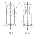
- Figures 1A and 1 B show a connector 1, seen from the side in a first position and turned by 90°.
- the connector see also Figure 2, comprises an outer part 2 which is preferably made of a thermoplastics material that is chemically resistant to disinfectant such as ethyl alcohol.
- the outer part comprises an end 4 for receiving a tube and an end 5 for connecting to a medical device such as an insulin pump.
- the end 4 for receiving a tube comprises a cavity 6 as it is also seen in the sectional view in Figure 2.
- the end 5 for connecting to a medical device comprises a luer lock 21 in which a male luer-lock is preferably used.
- the end 5 comprises an external double-thread 29 for being mounted to preferably an insulin pump.
- the outer shape of the connector 1 is such that it is essentially cylindrically shaped, but wherein the end 4 for receiving the tube has a narrowed portion for providing an oval narrowing area 28. This serves to improve the gripping around the connector 1 during handling thereof.
- the outer part 2 has an outer essentially plane upper delimiting face 20. The distance from this and down to the lower delimiting face 34 is within the range 17 mm.
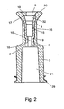
- Figure 2 is a sectional view wherein the joining between the two elements that constitute the connector 1 viz. the outer part 2 and the inner part 9 will appear.
- the outer part is manufactured such that there is liquid communication throughout its entire passage and it comprises axially a passage throughout its entire interior, wherein, in its end 5, it has such shape that it forms a luer lock 21. From said luer lock 21 an axial opening 3 to the cavity 6 is provided.
- the central axis of the opening 3 is axially parallel and coinciding with a through-going opening 10 provided in the inner part 9.
- the connector part 32 for the tube which is configured with side faces that diverge outwards towards an upper delimiting face 17, where said delimiting face 17 is of plane configuration.
- the interior area 35 and a further essentially conically shaped connecting area that may also constitute a part of the tube connector part and serve as glue reservoir are situated.
- the interior area is situated so that the glue ensuring connection between the tube and the inner part cannot be in liquid communication with the exterior of the connector.
- the inner part 9 is located so that its upper delimiting face17 is located at a distance from the upper delimiting face 20 of the outer part 2 as such. It should further be mentioned that the inner part 9 has on its outer circumference retention devices 15 e.g. in form of studs or wings that serve as undercuts whereby good gripping is ensured during moulding between the inner part 9 and the outer part 2.
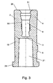
- the outer part 2 will be described with reference to Figure 3.
- the outer part 2 comprises as mentioned an essentially outer cylindrically shaped sleeve having essentially three cavities; a cavity in the end 5 comprising a luer lock 21 and preferably a male luer lock from which there is connection via a central opening 3 to the cavity 6 in the end of the outer part 2 for attaching the tube which interior faces are shaped to be essentially congruent with the outer faces of the inner part.
- the outer part 2 is manufactured from a chemically resistant material 13, whereby no stresses are released when it is wiped with e.g. ethyl alcohol.
- the inner part 9 will be described with reference to Figure 4. It also comprises a sleeve-like construction, its outer walls 14 being essentially cylindrical with various pouches/retention devices mounted thereon for providing good retention between the inner part and the outer part.
- the cavity of the inner part comprises essentially four areas, viz. a through-going opening 10 in communication with the inner area 35 being an essentially cylindrical area having a length of essentially about 3 mm and with a somewhat larger diameter than the opening 10; a conical area of about 1 mm forming the connection between the inner area and the tube connector part 32; and said tube connector part constituting the upper part of the inner part 9.
- This tube connector part is configured such that the walls diverge outwards towards the upper delimiting face 17 of the inner part 9 said face 17 being of essentially plane configuration.
- the outer walls of the inner part also comprise retention devices 15.
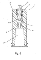
- connection between the tube and the inner part including the tube connector part 32 that may also be an area where the glue bonds and seals the remaining entrance, will be described in further detail with reference to Figure 5.
- It shows the joint between a connector 1 and a tube 24, wherein a section has been made through the connecting element and the tubular element.
- a luer-lock is shown and opposite to that the tubular element is located in the inner part 9 of the connecting element corresponding to the inner area 35.
- the tube connector part 32 is situated so that its upper delimiting face is located at a distance from the upper delimitating face 20 of the outer part.
- the risk of chemicals, if any, used for wiping the outer face of the outer part penetrating downwards to the inner area 35 of the inner part as such will be small due, on the one hand to said distance and, on the other hand, to the sealing properties of the glue.
- This is essential since the inner part is manufactured precisely from a plastics material that provides good connection to the tube when a soft glue is selected. This plastics material is not resistant to the material used for wiping. Conversely, a material that tolerates wiping with chemicals, including e.g. ethyl alcohol is used for the outer part.
- soft glue it is inherently more flexible than hard glue.
- a soft glue is used precisely in order to enable the plastic tube to retain its flexibility in the in-use situation.
Landscapes
- Engineering & Computer Science (AREA)
- Health & Medical Sciences (AREA)
- Heart & Thoracic Surgery (AREA)
- General Engineering & Computer Science (AREA)
- Mechanical Engineering (AREA)
- Animal Behavior & Ethology (AREA)
- Hematology (AREA)
- Life Sciences & Earth Sciences (AREA)
- Biomedical Technology (AREA)
- General Health & Medical Sciences (AREA)
- Public Health (AREA)
- Veterinary Medicine (AREA)
- Manufacturing & Machinery (AREA)
- Anesthesiology (AREA)
- Pulmonology (AREA)
- Infusion, Injection, And Reservoir Apparatuses (AREA)
- Injection Moulding Of Plastics Or The Like (AREA)
- Materials For Medical Uses (AREA)
Claims (13)
- Medizinischer Konnektor (1) zum Verbinden eines Rohres/Schlauches (24) mit einer medizinischen Vorrichtung, der medizinische Konnektor (1) ein erstes Ende (4), ein zweites Ende (5), eine durchgehende Bohrung und mindestens an dem ersten Ende (4) ein inneres Teil (9) und ein äußeres Teil (2) aufweist; der innere Teil (9) eine Höhlung (10, 32, 35) zum andauernden Festmachen des Endes des Rohres/Schlauches an den Konnektor und eine abgrenzende Oberfläche (17) an dem ersten Ende (4) aufweist; der äußere Teil (2) eine abgrenzende Oberfläche (20) an dem ersten Ende aufweist, die abgrenzende Oberfläche (17) des inneren Teils (9) von der abgrenzenden Oberfläche (20) des äußeren Teils (2) zurückgezogen ist; der äußere Teil (2) aus einem thermoplastischen Material angefertigt ist, das gegenüber Veränderungen widerstandsfähig ist, wenn es dem Einfluss eines Desinfektionsmittels unterworfen wird und der innere Teil (9) aus einem thermoplastischen Material angefertigt ist, welches mit einem weichen Klebstoff (8) vereinbar ist; und die Höhlung des inneren Teils (9) neben seiner abgrenzenden Oberfläche (17) eine im Wesentlichen konisch geformte Verbindungsfläche (32) aufweist, die einen zunehmenden Durchmesser zu dem ersten Ende (4) aufweist, dadurch gekennzeichnet, dass ein Rohr/Schlauch (24) andauernd in der Höhlung (32, 35) des inneren Teils (9) mit einem weichen Klebstoff befestigt ist, worin der Klebstoff sich zwischen der äußeren Oberfläche des Rohres/Schlauches (24) und der im Wesentlichen konisch geformten Verbindungsfläche (32) der Höhlung befindet und dass der innere (9) und der äußere (2) Teil auf so eine Weise verbunden sind, dass sie nicht im Stande sind, um die Längsachse herum zu rotieren und dass der innere Teil (9) nicht im Stande ist, mit den Desinfektionsmitteln, die verwendet werden, um den Konnektor vor dem Gebrauch abzuwischen, in Kontakt zu kommen.
- Medizinischer Konnektor nach Anspruch 1, dadurch gekennzeichnet, dass das thermoplastische Material für das innere Teil (9) ein amorphes Plastikmaterial ist.
- Medizinischer Konnektor nach einem der vorhergehenden Ansprüche, dadurch gekennzeichnet, dass das thermoplastische Material für das innere Teil (9) ein ABS Material ist.
- Medizinischer Konnektor nach einem der vorhergehenden Ansprüche, dadurch gekennzeichnet, dass das Plastikmaterial für das äußere Teil (2) ein mindestens teilweise kristallines Plastikmaterial ist.
- Medizinischer Konnektor nach einem der vorhergehenden Ansprüche, dadurch gekennzeichnet, dass das Plastikmaterial für das äußere Teil (2) ein Polypropylen ist.
- Medizinischer Konnektor nach einem der vorhergehenden Ansprüche, dadurch gekennzeichnet, dass die äußeren Wände des inneren Teils (9) von dem äußeren Teil (2) eingeschlossen sind und Retentionsvorrichtungen (15) umfassen.
- Medizinischer Konnektor nach einem der vorhergehenden Ansprüche, dadurch gekennzeichnet, dass der innere Teil (9) ein im Wesentlichen rotationssymmetrischer Körper mit einer rotationssymmetrischen durchgehenden Öffnung (3) ist.
- Medizinischer Konnektor nach einem der vorhergehenden Ansprüche, dadurch gekennzeichnet, dass der Konnektor (1) ein Luer-Lock umfasst (21).
- Eine Infusionsvorrichtung, die den Konnektor nach Anspruch 1 umfasst, worin das zweite Ende (5) des Konnektors mit einer Insulinpumpe verbunden ist.
- Verfahren zum Spritzgießen eines Konnektors (1) nach Anspruch 1, folgende Schritte umfassend:- Spritzen eines Plastikmaterials, das mit einem weichen Klebstoff vereinbar ist, in eine Gussform, die eine Höhlung von gewünschter Gestalt und ein Kernstück von gewünschter Gestalt aufweist, zum Formen einer Höhlung in dem Konnektor zum andauernden Befestigen eines Endes eines Rohres/Schlauches (24),- Spritzen eines Plastikmaterials, das gegenüber Veränderungen widerstandsfähig ist, wenn es dem Einfluss eines Desinfektionsmittels unterworfen wird, in eine Gussform, die eine Höhlung von gewünschter Gestalt, ein Kernstück zum Ausbilden einer durchgehenden Öffnung aufweist,- Verwenden eines Teils der Oberfläche des als ersten gespritzten Plastikmaterials als Teil der Gussform, die das als zweites gespritzte Plastikmaterial aufnimmt,- Zusammenbauen des Konnektors (1) und des Rohres/Schlauches (24) mittels eines weichen Klebstoffs (8).
- Verfahren nach Anspruch 10, dadurch gekennzeichnet, dass beide Plastikmaterialien thermoplastische Materialien sind.
- Verfahren nach Anspruch 10 oder 11, dadurch gekennzeichnet, dass das Plastikmaterial für das innere Teil (9) ein amorphes Plastikmaterial, vorzugsweise ein ABS-Material, ist.
- Verfahren nach einem der Ansprüche 10-12, dadurch gekennzeichnet, dass das Plastikmaterial für das äußere Teil (2) ein mindestens teilweise kristallines Plastikmaterial, vorzugsweise ein Polypropylen, ist.
Applications Claiming Priority (5)
| Application Number | Priority Date | Filing Date | Title |
|---|---|---|---|
| US437488 | 1989-11-15 | ||
| DKPA200300207 | 2003-02-12 | ||
| DK200300207 | 2003-02-12 | ||
| US10/437,488 US20040155457A1 (en) | 2003-02-12 | 2003-05-13 | Connecting element comprising a first body and a method for injection moulding a connecting element |
| PCT/DK2004/000100 WO2004071568A1 (en) | 2003-02-12 | 2004-02-12 | A medical connector and a method of injection moulding such a connector |
Publications (2)
| Publication Number | Publication Date |
|---|---|
| EP1599249A1 EP1599249A1 (de) | 2005-11-30 |
| EP1599249B1 true EP1599249B1 (de) | 2006-11-29 |
Family
ID=32870665
Family Applications (1)
| Application Number | Title | Priority Date | Filing Date |
|---|---|---|---|
| EP04710340A Expired - Lifetime EP1599249B1 (de) | 2003-02-12 | 2004-02-12 | Medizinischer Konnektor und Verfahren zum Spritzgießen eines solchen Konnektors |
Country Status (7)
| Country | Link |
|---|---|
| US (1) | US7455325B2 (de) |
| EP (1) | EP1599249B1 (de) |
| AT (1) | ATE346646T1 (de) |
| CA (1) | CA2555464C (de) |
| DE (1) | DE602004003477T2 (de) |
| DK (1) | DK1599249T3 (de) |
| WO (1) | WO2004071568A1 (de) |
Cited By (2)
| Publication number | Priority date | Publication date | Assignee | Title |
|---|---|---|---|---|
| US10569074B2 (en) | 2016-02-03 | 2020-02-25 | B. Braun Avitum Ag | Medical coupling and medical system comprising medical coupling |
| US11666729B2 (en) | 2017-11-03 | 2023-06-06 | Hollister Incorporated | Methods of bonding components to polymeric substrates |
Families Citing this family (24)
| Publication number | Priority date | Publication date | Assignee | Title |
|---|---|---|---|---|
| JP2007143813A (ja) * | 2005-11-28 | 2007-06-14 | Nippon Sherwood Medical Industries Ltd | 医療用活栓 |
| FR2900817B1 (fr) | 2006-05-12 | 2008-12-19 | Gambro Lundia Ab | Bandage a usage medical pour un tube implante dans un patient, ainsi que le procede d'application de ce bandage sur la peau d'un patient |
| US8336152B2 (en) | 2007-04-02 | 2012-12-25 | C. R. Bard, Inc. | Insert for a microbial scrubbing device |
| US9192449B2 (en) | 2007-04-02 | 2015-11-24 | C. R. Bard, Inc. | Medical component scrubbing device with detachable cap |
| WO2009097327A1 (en) * | 2008-01-28 | 2009-08-06 | Colder Products Company | Quick connect/disconnect coupling assemblies |
| US8353876B2 (en) | 2008-01-30 | 2013-01-15 | Becton, Dickinson And Company | Occlusion resistant catheters |
| US8696820B2 (en) * | 2008-03-31 | 2014-04-15 | Bard Access Systems, Inc. | Method of removing a biofilm from a surface |
| US8372057B2 (en) * | 2008-10-10 | 2013-02-12 | Coeur, Inc. | Luer lock adapter |
| CA2757080C (en) | 2009-04-01 | 2017-03-14 | C. R. Bard, Inc. | Microbial scrubbing device |
| CN102413868B (zh) * | 2009-04-23 | 2013-08-21 | 株式会社Jms | 医疗用连接器 |
| US20120078215A1 (en) * | 2010-09-28 | 2012-03-29 | Tyco Healthcare Group Lp | Two-piece vial transfer needle assembly |
| US9339640B2 (en) * | 2011-02-11 | 2016-05-17 | Carefusion 303, Inc. | Connector for multiple sizes of tubing |
| WO2012151558A2 (en) | 2011-05-04 | 2012-11-08 | Gallagher Anthony David | Coupling for pvc piping sections |
| US20150316188A1 (en) * | 2012-06-29 | 2015-11-05 | University Of South Australia | Fluid connection ports |
| US9750928B2 (en) | 2013-02-13 | 2017-09-05 | Becton, Dickinson And Company | Blood control IV catheter with stationary septum activator |
| US9789279B2 (en) | 2014-04-23 | 2017-10-17 | Becton, Dickinson And Company | Antimicrobial obturator for use with vascular access devices |
| US10376686B2 (en) | 2014-04-23 | 2019-08-13 | Becton, Dickinson And Company | Antimicrobial caps for medical connectors |
| US9675793B2 (en) | 2014-04-23 | 2017-06-13 | Becton, Dickinson And Company | Catheter tubing with extraluminal antimicrobial coating |
| US10232088B2 (en) | 2014-07-08 | 2019-03-19 | Becton, Dickinson And Company | Antimicrobial coating forming kink resistant feature on a vascular access device |
| US10493244B2 (en) | 2015-10-28 | 2019-12-03 | Becton, Dickinson And Company | Extension tubing strain relief |
| US10557573B2 (en) * | 2016-11-04 | 2020-02-11 | United Technologies Corporation | Feed through seals and fittings |
| US12465722B2 (en) * | 2019-06-19 | 2025-11-11 | Kaneka Corporation | Reinforced catheter with tapered proximal lumen |
| DE102019219245A1 (de) * | 2019-12-10 | 2021-06-10 | B. Braun Melsungen Aktiengesellschaft | Konnektor, System mit Konnektor und Schlauchleitung sowie Verfahren zum Verbinden eines Konnektors mit einer Schlauchleitung |
| JP2023056709A (ja) * | 2021-10-08 | 2023-04-20 | 株式会社ジェイ・エム・エス | チューブ付き医療用コネクタ |
Family Cites Families (36)
| Publication number | Priority date | Publication date | Assignee | Title |
|---|---|---|---|---|
| US3469579A (en) | 1967-05-05 | 1969-09-30 | Becton Dickinson Co | Catheter needle |
| GB1437352A (en) * | 1972-12-11 | 1976-05-26 | British Wire Products Ltd | Joints or connectors |
| US4346704A (en) | 1980-09-09 | 1982-08-31 | Baxter Travenol Laboratories, Inc. | Sleeve valve for parenteral solution device |
| DE3150052C2 (de) | 1981-12-17 | 1985-02-21 | Sterimed Gesellschaft für medizinischen Bedarf mbH, 6600 Saarbrücken | Katheter zur Katheterung zentraler Venen |
| US5776116A (en) | 1983-01-24 | 1998-07-07 | Icu Medical, Inc. | Medical connector |
| US5199947A (en) | 1983-01-24 | 1993-04-06 | Icu Medical, Inc. | Method of locking an influent line to a piggyback connector |
| US4790829A (en) * | 1983-08-24 | 1988-12-13 | Russell Bowden | Reusable injection catheter |
| ZA85151B (en) | 1984-01-25 | 1985-08-28 | Squibb & Sons Inc | Quick disconnect tube coupling |
| JPS61113467A (ja) * | 1984-11-06 | 1986-05-31 | テルモ株式会社 | 医療用具 |
| JPS61113468A (ja) * | 1984-11-06 | 1986-05-31 | テルモ株式会社 | 医療用具 |
| US4693710A (en) | 1985-03-13 | 1987-09-15 | Sherwood Medical Company | Tube and fitting assembly and method of making same |
| SE462538B (sv) | 1986-06-06 | 1990-07-09 | Gambro Ab | Kopplingsdetalj foer slangar eller dylikt |
| US4874377A (en) | 1988-05-26 | 1989-10-17 | Davis Newgard Revocable Family Living Trust | Self-occluding intravascular cannula assembly |
| US4878900A (en) | 1988-07-27 | 1989-11-07 | Sundt Thoralf M | Surgical probe and suction device |
| NL8902307A (nl) | 1989-09-14 | 1991-04-02 | Cordis Europ | Catheter. |
| US5586977A (en) | 1990-01-26 | 1996-12-24 | C.R. Bard, Inc. | Quick disconnect fitting for coupling interchangeable probe tip to laparoscopic instrument |
| US5380301A (en) * | 1992-07-10 | 1995-01-10 | Sherwood Medical Company | Catheter/hub strain relief and method of manufacture thereof |
| GB9514011D0 (en) | 1995-07-10 | 1995-09-06 | Squibb & Sons Inc | Tube coupling |
| US5611576A (en) | 1995-11-24 | 1997-03-18 | Industrie Borla Spa | Female coupling element for haemodialysis medical equipment |
| US6017319A (en) | 1996-05-24 | 2000-01-25 | Precision Vascular Systems, Inc. | Hybrid tubular guide wire for catheters |
| US5782505A (en) | 1996-08-29 | 1998-07-21 | Becton, Dickinson And Company | Catheter adapter assembly |
| US5735813A (en) * | 1996-10-23 | 1998-04-07 | Danron, Inc. | Double lumen introducing needle |
| AU5651798A (en) | 1997-01-29 | 1998-09-08 | Jes Tougaard Gram | Procedure and machinery for the moulding of an assembled object |
| US5803509A (en) | 1997-04-28 | 1998-09-08 | Adams; Robert D. | Line connector lock |
| US5997562A (en) | 1997-06-13 | 1999-12-07 | Percusurge, Inc. | Medical wire introducer and balloon protective sheath |
| DE29712676U1 (de) * | 1997-07-17 | 1997-11-13 | Rycyk, Manfred, 34327 Körle | Knickschutz für Katheter |
| JPH11313896A (ja) * | 1998-05-01 | 1999-11-16 | Kawasumi Lab Inc | メスコネクタ |
| US6332874B1 (en) | 1998-08-28 | 2001-12-25 | C.R. Bard, Inc. | Coupling and stabilization system for proximal end of catheter |
| US6273478B1 (en) | 1999-03-30 | 2001-08-14 | The Regents Of The University Of California | Microfluidic interconnects |
| US7150845B1 (en) | 1999-05-17 | 2006-12-19 | Jes Tougaard Gram | Mould with turnable middle section |
| US6260890B1 (en) | 1999-08-12 | 2001-07-17 | Breg, Inc. | Tubing connector |
| US6575959B1 (en) | 1999-12-27 | 2003-06-10 | Scimed Life Systems, Inc. | Catheter incorporating an insert molded hub and method of manufacturing |
| US6651956B2 (en) | 2002-01-31 | 2003-11-25 | Halkey-Roberts Corporation | Slit-type swabable valve |
| US20040100093A1 (en) * | 2002-11-21 | 2004-05-27 | Leigh-Monstevens Keith V. | Co-extruded tube with molded connector |
| WO2005025661A2 (en) * | 2003-09-11 | 2005-03-24 | Cook Incorporated | Catheter having an overmolded hub |
| US20060259012A1 (en) * | 2005-05-13 | 2006-11-16 | Tri-State Hospital Supply Corporation | PIV high pressure infusion set |
-
2004
- 2004-02-12 EP EP04710340A patent/EP1599249B1/de not_active Expired - Lifetime
- 2004-02-12 DK DK04710340T patent/DK1599249T3/da active
- 2004-02-12 CA CA2555464A patent/CA2555464C/en not_active Expired - Fee Related
- 2004-02-12 DE DE602004003477T patent/DE602004003477T2/de not_active Expired - Lifetime
- 2004-02-12 AT AT04710340T patent/ATE346646T1/de not_active IP Right Cessation
- 2004-02-12 WO PCT/DK2004/000100 patent/WO2004071568A1/en not_active Ceased
- 2004-12-29 US US11/024,892 patent/US7455325B2/en not_active Expired - Lifetime
Cited By (2)
| Publication number | Priority date | Publication date | Assignee | Title |
|---|---|---|---|---|
| US10569074B2 (en) | 2016-02-03 | 2020-02-25 | B. Braun Avitum Ag | Medical coupling and medical system comprising medical coupling |
| US11666729B2 (en) | 2017-11-03 | 2023-06-06 | Hollister Incorporated | Methods of bonding components to polymeric substrates |
Also Published As
| Publication number | Publication date |
|---|---|
| US7455325B2 (en) | 2008-11-25 |
| CA2555464A1 (en) | 2004-08-26 |
| DE602004003477T2 (de) | 2007-10-04 |
| DK1599249T3 (da) | 2007-04-02 |
| DE602004003477D1 (de) | 2007-01-11 |
| CA2555464C (en) | 2011-11-08 |
| ATE346646T1 (de) | 2006-12-15 |
| WO2004071568A1 (en) | 2004-08-26 |
| US20050142945A1 (en) | 2005-06-30 |
| EP1599249A1 (de) | 2005-11-30 |
Similar Documents
| Publication | Publication Date | Title |
|---|---|---|
| EP1599249B1 (de) | Medizinischer Konnektor und Verfahren zum Spritzgießen eines solchen Konnektors | |
| JP5238804B2 (ja) | 事前充填シリンジ用の確動移動ストッパ | |
| US12311081B2 (en) | Antimicrobial inserts for medical devices | |
| US10668221B2 (en) | Plunger covers and plungers for use in syringes | |
| US20040155457A1 (en) | Connecting element comprising a first body and a method for injection moulding a connecting element | |
| JPWO2001005456A1 (ja) | シリンジ用プランジャ | |
| AU2011351446B2 (en) | Catheter with integrated insertion aid | |
| US10099032B2 (en) | Catheter with integrated insertion aid | |
| ES2375176T3 (es) | Procedimientos de moldeo por inyección para producir catéteres. | |
| CA2451364A1 (en) | A method of producing a catheter and a catheter | |
| US7947146B2 (en) | Plastic carpule and method of manufacture | |
| US20100280370A1 (en) | Syringe plunger | |
| US10716927B2 (en) | Extrudable tubing for delivery of medicinal fluids | |
| EP3086825B1 (de) | Medizintechnisches messsystem und verfahren zur herstellung des messsystems | |
| KR20180080110A (ko) | 상이한 재료로 이루어진 주사기 | |
| EP0824921A1 (de) | Medizinischer Filter | |
| JPH09628A (ja) | 二液成分用注射器 | |
| WO2016100848A1 (en) | Catheter with integrated insertion aid | |
| JP2001046516A (ja) | 雌ルアーアダプター | |
| WO2000027605A1 (en) | Method of forming a reseal element for a needleless injection site |
Legal Events
| Date | Code | Title | Description |
|---|---|---|---|
| PUAI | Public reference made under article 153(3) epc to a published international application that has entered the european phase |
Free format text: ORIGINAL CODE: 0009012 |
|
| 17P | Request for examination filed |
Effective date: 20050908 |
|
| AK | Designated contracting states |
Kind code of ref document: A1 Designated state(s): AT BE BG CH CY CZ DE DK EE ES FI FR GB GR HU IE IT LI LU MC NL PT RO SE SI SK TR |
|
| AX | Request for extension of the european patent |
Extension state: AL LT LV MK |
|
| GRAP | Despatch of communication of intention to grant a patent |
Free format text: ORIGINAL CODE: EPIDOSNIGR1 |
|
| RTI1 | Title (correction) |
Free format text: A MEDICAL CONNECTOR AND A METHOD OF INJECTION MOULDING SUCH A CONNECTOR |
|
| GRAS | Grant fee paid |
Free format text: ORIGINAL CODE: EPIDOSNIGR3 |
|
| GRAA | (expected) grant |
Free format text: ORIGINAL CODE: 0009210 |
|
| AK | Designated contracting states |
Kind code of ref document: B1 Designated state(s): AT BE BG CH CY CZ DE DK EE ES FI FR GB GR HU IE IT LI LU MC NL PT RO SE SI SK TR |
|
| AX | Request for extension of the european patent |
Extension state: AL LT LV MK |
|
| PG25 | Lapsed in a contracting state [announced via postgrant information from national office to epo] |
Ref country code: AT Free format text: LAPSE BECAUSE OF FAILURE TO SUBMIT A TRANSLATION OF THE DESCRIPTION OR TO PAY THE FEE WITHIN THE PRESCRIBED TIME-LIMIT Effective date: 20061129 Ref country code: IT Free format text: LAPSE BECAUSE OF FAILURE TO SUBMIT A TRANSLATION OF THE DESCRIPTION OR TO PAY THE FEE WITHIN THE PRESCRIBED TIME-LIMIT;WARNING: LAPSES OF ITALIAN PATENTS WITH EFFECTIVE DATE BEFORE 2007 MAY HAVE OCCURRED AT ANY TIME BEFORE 2007. THE CORRECT EFFECTIVE DATE MAY BE DIFFERENT FROM THE ONE RECORDED. Effective date: 20061129 Ref country code: FI Free format text: LAPSE BECAUSE OF FAILURE TO SUBMIT A TRANSLATION OF THE DESCRIPTION OR TO PAY THE FEE WITHIN THE PRESCRIBED TIME-LIMIT Effective date: 20061129 Ref country code: BE Free format text: LAPSE BECAUSE OF FAILURE TO SUBMIT A TRANSLATION OF THE DESCRIPTION OR TO PAY THE FEE WITHIN THE PRESCRIBED TIME-LIMIT Effective date: 20061129 Ref country code: CZ Free format text: LAPSE BECAUSE OF FAILURE TO SUBMIT A TRANSLATION OF THE DESCRIPTION OR TO PAY THE FEE WITHIN THE PRESCRIBED TIME-LIMIT Effective date: 20061129 Ref country code: SK Free format text: LAPSE BECAUSE OF FAILURE TO SUBMIT A TRANSLATION OF THE DESCRIPTION OR TO PAY THE FEE WITHIN THE PRESCRIBED TIME-LIMIT Effective date: 20061129 Ref country code: RO Free format text: LAPSE BECAUSE OF FAILURE TO SUBMIT A TRANSLATION OF THE DESCRIPTION OR TO PAY THE FEE WITHIN THE PRESCRIBED TIME-LIMIT Effective date: 20061129 Ref country code: SI Free format text: LAPSE BECAUSE OF FAILURE TO SUBMIT A TRANSLATION OF THE DESCRIPTION OR TO PAY THE FEE WITHIN THE PRESCRIBED TIME-LIMIT Effective date: 20061129 Ref country code: NL Free format text: LAPSE BECAUSE OF FAILURE TO SUBMIT A TRANSLATION OF THE DESCRIPTION OR TO PAY THE FEE WITHIN THE PRESCRIBED TIME-LIMIT Effective date: 20061129 |
|
| REG | Reference to a national code |
Ref country code: GB Ref legal event code: FG4D |
|
| REG | Reference to a national code |
Ref country code: CH Ref legal event code: EP |
|
| REG | Reference to a national code |
Ref country code: IE Ref legal event code: FG4D |
|
| REF | Corresponds to: |
Ref document number: 602004003477 Country of ref document: DE Date of ref document: 20070111 Kind code of ref document: P |
|
| PG25 | Lapsed in a contracting state [announced via postgrant information from national office to epo] |
Ref country code: MC Free format text: LAPSE BECAUSE OF NON-PAYMENT OF DUE FEES Effective date: 20070228 Ref country code: BG Free format text: LAPSE BECAUSE OF FAILURE TO SUBMIT A TRANSLATION OF THE DESCRIPTION OR TO PAY THE FEE WITHIN THE PRESCRIBED TIME-LIMIT Effective date: 20070228 Ref country code: SE Free format text: LAPSE BECAUSE OF FAILURE TO SUBMIT A TRANSLATION OF THE DESCRIPTION OR TO PAY THE FEE WITHIN THE PRESCRIBED TIME-LIMIT Effective date: 20070228 |
|
| PG25 | Lapsed in a contracting state [announced via postgrant information from national office to epo] |
Ref country code: ES Free format text: LAPSE BECAUSE OF FAILURE TO SUBMIT A TRANSLATION OF THE DESCRIPTION OR TO PAY THE FEE WITHIN THE PRESCRIBED TIME-LIMIT Effective date: 20070312 |
|
| REG | Reference to a national code |
Ref country code: DK Ref legal event code: T3 |
|
| PG25 | Lapsed in a contracting state [announced via postgrant information from national office to epo] |
Ref country code: PT Free format text: LAPSE BECAUSE OF FAILURE TO SUBMIT A TRANSLATION OF THE DESCRIPTION OR TO PAY THE FEE WITHIN THE PRESCRIBED TIME-LIMIT Effective date: 20070430 |
|
| REG | Reference to a national code |
Ref country code: CH Ref legal event code: NV Representative=s name: BUGNION S.A. |
|
| LTIE | Lt: invalidation of european patent or patent extension |
Effective date: 20061129 |
|
| NLV1 | Nl: lapsed or annulled due to failure to fulfill the requirements of art. 29p and 29m of the patents act | ||
| ET | Fr: translation filed | ||
| PLBE | No opposition filed within time limit |
Free format text: ORIGINAL CODE: 0009261 |
|
| STAA | Information on the status of an ep patent application or granted ep patent |
Free format text: STATUS: NO OPPOSITION FILED WITHIN TIME LIMIT |
|
| 26N | No opposition filed |
Effective date: 20070830 |
|
| PG25 | Lapsed in a contracting state [announced via postgrant information from national office to epo] |
Ref country code: IE Free format text: LAPSE BECAUSE OF NON-PAYMENT OF DUE FEES Effective date: 20070212 |
|
| PG25 | Lapsed in a contracting state [announced via postgrant information from national office to epo] |
Ref country code: GR Free format text: LAPSE BECAUSE OF FAILURE TO SUBMIT A TRANSLATION OF THE DESCRIPTION OR TO PAY THE FEE WITHIN THE PRESCRIBED TIME-LIMIT Effective date: 20070301 |
|
| PG25 | Lapsed in a contracting state [announced via postgrant information from national office to epo] |
Ref country code: EE Free format text: LAPSE BECAUSE OF FAILURE TO SUBMIT A TRANSLATION OF THE DESCRIPTION OR TO PAY THE FEE WITHIN THE PRESCRIBED TIME-LIMIT Effective date: 20061129 |
|
| PG25 | Lapsed in a contracting state [announced via postgrant information from national office to epo] |
Ref country code: LU Free format text: LAPSE BECAUSE OF NON-PAYMENT OF DUE FEES Effective date: 20070212 Ref country code: CY Free format text: LAPSE BECAUSE OF FAILURE TO SUBMIT A TRANSLATION OF THE DESCRIPTION OR TO PAY THE FEE WITHIN THE PRESCRIBED TIME-LIMIT Effective date: 20061129 |
|
| PG25 | Lapsed in a contracting state [announced via postgrant information from national office to epo] |
Ref country code: HU Free format text: LAPSE BECAUSE OF FAILURE TO SUBMIT A TRANSLATION OF THE DESCRIPTION OR TO PAY THE FEE WITHIN THE PRESCRIBED TIME-LIMIT Effective date: 20070530 Ref country code: TR Free format text: LAPSE BECAUSE OF FAILURE TO SUBMIT A TRANSLATION OF THE DESCRIPTION OR TO PAY THE FEE WITHIN THE PRESCRIBED TIME-LIMIT Effective date: 20061129 |
|
| PGFP | Annual fee paid to national office [announced via postgrant information from national office to epo] |
Ref country code: CH Payment date: 20120214 Year of fee payment: 9 |
|
| PGFP | Annual fee paid to national office [announced via postgrant information from national office to epo] |
Ref country code: DK Payment date: 20120210 Year of fee payment: 9 |
|
| REG | Reference to a national code |
Ref country code: DK Ref legal event code: EBP |
|
| REG | Reference to a national code |
Ref country code: CH Ref legal event code: PL |
|
| PG25 | Lapsed in a contracting state [announced via postgrant information from national office to epo] |
Ref country code: LI Free format text: LAPSE BECAUSE OF NON-PAYMENT OF DUE FEES Effective date: 20130228 Ref country code: CH Free format text: LAPSE BECAUSE OF NON-PAYMENT OF DUE FEES Effective date: 20130228 |
|
| PG25 | Lapsed in a contracting state [announced via postgrant information from national office to epo] |
Ref country code: DK Free format text: LAPSE BECAUSE OF NON-PAYMENT OF DUE FEES Effective date: 20130228 |
|
| REG | Reference to a national code |
Ref country code: FR Ref legal event code: PLFP Year of fee payment: 13 |
|
| REG | Reference to a national code |
Ref country code: FR Ref legal event code: PLFP Year of fee payment: 14 |
|
| REG | Reference to a national code |
Ref country code: FR Ref legal event code: PLFP Year of fee payment: 15 |
|
| REG | Reference to a national code |
Ref country code: DE Ref legal event code: R082 Ref document number: 602004003477 Country of ref document: DE Representative=s name: GLEISS GROSSE SCHRELL UND PARTNER MBB PATENTAN, DE |
|
| PGFP | Annual fee paid to national office [announced via postgrant information from national office to epo] |
Ref country code: DE Payment date: 20220224 Year of fee payment: 19 |
|
| PGFP | Annual fee paid to national office [announced via postgrant information from national office to epo] |
Ref country code: FR Payment date: 20230119 Year of fee payment: 20 |
|
| PGFP | Annual fee paid to national office [announced via postgrant information from national office to epo] |
Ref country code: GB Payment date: 20230121 Year of fee payment: 20 |
|
| P01 | Opt-out of the competence of the unified patent court (upc) registered |
Effective date: 20230525 |
|
| REG | Reference to a national code |
Ref country code: DE Ref legal event code: R119 Ref document number: 602004003477 Country of ref document: DE |
|
| PG25 | Lapsed in a contracting state [announced via postgrant information from national office to epo] |
Ref country code: DE Free format text: LAPSE BECAUSE OF NON-PAYMENT OF DUE FEES Effective date: 20230901 |
|
| REG | Reference to a national code |
Ref country code: GB Ref legal event code: PE20 Expiry date: 20240211 |
|
| PG25 | Lapsed in a contracting state [announced via postgrant information from national office to epo] |
Ref country code: GB Free format text: LAPSE BECAUSE OF EXPIRATION OF PROTECTION Effective date: 20240211 |