EP1599234B1 - Vorrichtung zum sterilisieren von wasser - Google Patents
Vorrichtung zum sterilisieren von wasser Download PDFInfo
- Publication number
- EP1599234B1 EP1599234B1 EP04713108.1A EP04713108A EP1599234B1 EP 1599234 B1 EP1599234 B1 EP 1599234B1 EP 04713108 A EP04713108 A EP 04713108A EP 1599234 B1 EP1599234 B1 EP 1599234B1
- Authority
- EP
- European Patent Office
- Prior art keywords
- ultraviolet radiation
- source
- water
- flow
- lamp
- Prior art date
- Legal status (The legal status is an assumption and is not a legal conclusion. Google has not performed a legal analysis and makes no representation as to the accuracy of the status listed.)
- Expired - Lifetime
Links
Images


Classifications
-
- E—FIXED CONSTRUCTIONS
- E03—WATER SUPPLY; SEWERAGE
- E03C—DOMESTIC PLUMBING INSTALLATIONS FOR FRESH WATER OR WASTE WATER; SINKS
- E03C1/00—Domestic plumbing installations for fresh water or waste water; Sinks
- E03C1/02—Plumbing installations for fresh water
- E03C1/04—Water-basin installations specially adapted to wash-basins or baths
- E03C1/0408—Water installations especially for showers
-
- A—HUMAN NECESSITIES
- A61—MEDICAL OR VETERINARY SCIENCE; HYGIENE
- A61L—METHODS OR APPARATUS FOR STERILISING MATERIALS OR OBJECTS IN GENERAL; DISINFECTION, STERILISATION OR DEODORISATION OF AIR; CHEMICAL ASPECTS OF BANDAGES, DRESSINGS, ABSORBENT PADS OR SURGICAL ARTICLES; MATERIALS FOR BANDAGES, DRESSINGS, ABSORBENT PADS OR SURGICAL ARTICLES
- A61L2/00—Disinfection or sterilisation of materials or objects, in general; Accessories therefor
- A61L2/02—Disinfection or sterilisation of materials or objects, in general; Accessories therefor using physical processes
- A61L2/08—Radiation
- A61L2/10—Ultraviolet [UV] radiation
-
- C—CHEMISTRY; METALLURGY
- C02—TREATMENT OF WATER, WASTE WATER, SEWAGE, OR SLUDGE
- C02F—TREATMENT OF WATER, WASTE WATER, SEWAGE, OR SLUDGE
- C02F1/00—Treatment of water, waste water, or sewage
- C02F1/30—Treatment of water, waste water, or sewage by irradiation
- C02F1/32—Treatment of water, waste water, or sewage by irradiation with ultraviolet light
- C02F1/325—Irradiation devices or lamp constructions
-
- F—MECHANICAL ENGINEERING; LIGHTING; HEATING; WEAPONS; BLASTING
- F24—HEATING; RANGES; VENTILATING
- F24D—DOMESTIC- OR SPACE-HEATING SYSTEMS, e.g. CENTRAL HEATING SYSTEMS; DOMESTIC HOT-WATER SUPPLY SYSTEMS; ELEMENTS OR COMPONENTS THEREFOR
- F24D17/00—Domestic hot-water supply systems
- F24D17/0073—Arrangements for preventing the occurrence or proliferation of microorganisms in the water
-
- C—CHEMISTRY; METALLURGY
- C02—TREATMENT OF WATER, WASTE WATER, SEWAGE, OR SLUDGE
- C02F—TREATMENT OF WATER, WASTE WATER, SEWAGE, OR SLUDGE
- C02F2201/00—Apparatus for treatment of water, waste water or sewage
- C02F2201/32—Details relating to UV-irradiation devices
- C02F2201/322—Lamp arrangement
- C02F2201/3223—Single elongated lamp located on the central axis of a turbular reactor
-
- C—CHEMISTRY; METALLURGY
- C02—TREATMENT OF WATER, WASTE WATER, SEWAGE, OR SLUDGE
- C02F—TREATMENT OF WATER, WASTE WATER, SEWAGE, OR SLUDGE
- C02F2201/00—Apparatus for treatment of water, waste water or sewage
- C02F2201/32—Details relating to UV-irradiation devices
- C02F2201/326—Lamp control systems
-
- C—CHEMISTRY; METALLURGY
- C02—TREATMENT OF WATER, WASTE WATER, SEWAGE, OR SLUDGE
- C02F—TREATMENT OF WATER, WASTE WATER, SEWAGE, OR SLUDGE
- C02F2307/00—Location of water treatment or water treatment device
- C02F2307/06—Mounted on or being part of a faucet, shower handle or showerhead
-
- E—FIXED CONSTRUCTIONS
- E03—WATER SUPPLY; SEWERAGE
- E03C—DOMESTIC PLUMBING INSTALLATIONS FOR FRESH WATER OR WASTE WATER; SINKS
- E03C2201/00—Details, devices or methods not otherwise provided for
- E03C2201/40—Arrangement of water treatment devices in domestic plumbing installations
Definitions
- the present invention relates to a device for sterilising a flow of water in particular to a device for sterilising a flow of water using ultraviolet radiation.
- bacteria and other micro-organisms can be killed by the use of electromagnetic radiation such as ultraviolet radiation.
- ultraviolet radiation may be used to sterilise a source of water by passing the water near to a source of ultraviolet radiation for a sufficient time for any micro-organisms to be killed. It is also known to use this process in a batch or a continuous manner
- GB2175777 discloses a portable water steriliser having two connected chambers, one has a spout and an UV lamp. Water is poured into the other chamber, and then the device is tilted so that the water flows into the chamber with the UV lamp and out of the spout.
- WO00/78366 discloses a shower head provided with an ultraviolet lamp with a hermetically sealed housing. The housing contains a transformer and a humidity sensor.
- One particular use of such water sterilisation devices is to sterilise the water for use in a shower. Because of their nature, showers can produce a fine mist which may be inhaled by the user of the shower. If the water is infected with the legionella bacteria this can have potentially fatal results.
- Some prior art devices contain ultraviolet sources which are periodically turned off if no water is flowing. If the water begins to flow before the ultraviolet source reaches optimum performance, there is a danger of micro-organisms flowing past the ultraviolet source without being killed.
- a device for sterilising a flow of water according to claim 1.
- the outlet portion defines an elongate volume extending away from the source of ultraviolet radiation.
- the at least one aperture leads to an open air space.
- the outlet portion extends continuously to the source of ultraviolet radiation.
- the device further comprises a casing which prevents removal of the shower head.
- the device comprises stainless steel.
- the source of ultraviolet radiation is an ultraviolet lamp.
- the source of ultraviolet radiation is contained within a quartz housing.
- the device is positioned in use with the outlet portion projecting at least partly upwardly from the remainder of the device.
- the device is arranged such that the source of ultraviolet radiation is shut off if the device is opened.
- the device comprises means to shut off the flow of water if the source of ultraviolet radiation is off.
- the means to shut off the flow of water comprises a pulse latching valve.
- the means to shut off the flow of water is powered by a capacitor.
- the device further comprises means to prevent flow of water through the device for a predetermined period of time after the source of ultraviolet radiation is activated.
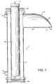
- a device according to the invention is shown generally at 2, having a substantially tubular configuration.
- the device 2 is described herein with reference to a unit to provide sterile water for a shower.
- the present invention has a wide range of applications such as use in medical, consumer and food related environments such as hotels and hospitals.
- the device 2 comprises an elongate chamber 4 bounded by a substantially cylindrical wall. In use, the device 2 is positioned in a substantially vertical configuration, as explained below.
- an inlet 6 for the passage of water into the chamber 4.
- an opening 8 the purpose of which will be described below.
- an outlet 10 having a substantially tubular configuration which projects and tapers away from the chamber 4.
- the outlet 10 has a lower wall 12 which extends in a substantially straight line away from the chamber 4.
- the outlet 10 has an upper wall 14 which curves down to meet the lower wall 12.
- a region of the lower wall 12 is provided with a number of apertures 16, thus forming a shower rose.
- a tubular ultraviolet (UV) lamp 18 is located substantially centrally along the longitudinal axis of the chamber 4.
- the UV lamp 18 is located within a concentric cylindrical quartz sleeve 20.
- Liquid-tight fittings 22 and 24 are located at the ends of the chamber 4 to locate the quartz sleeve 20 and the UV lamp 18 within the chamber 4 in a liquid-tight manner.
- Outlet 8 positioned towards the upper end of chamber 4. Outlet 8 leads to a sensor which detects whether the UV lamp 18 is turned on or off.
- Water may enter the device 2 through inlet 6 and pass into the annular space in chamber 4 around the quartz sleeve 20.
- the water flows up and around the quartz sleeve 20, being irradiated by the UV lamp 18.
- the water then flows through the outlet 10 and passes out of the device 2 through the apertures 16.
- the device 2 thus provides a spray of water in a similar way to a traditional shower.
- the device 2 Whilst water is flowing, the device 2 is arranged such that any micro-organisms present in the water are irradiated with enough ultraviolet radiation in order to kill them.
- the device 2 shown has a UV lamp 18 with a power of 15W and could safely sterilise a flow of water of up to 8 litres/minute. In use, the device 2 typically provides a maximum flow of around 6 litres/minute. If the sensor located at outlet 8 detects that the UV lamp 18 is turned off, it activates a valve which shuts off the water supply to inlet 6. Thus, the passage of water through the device 2 whilst the ultraviolet lamp 18 is turned off is prevented ensuring that only sterile water leaves the apertures 16.
- the outlet 10 is shaped and located relative to the UV lamp 18 such that all of the inner surfaces of outlet 10 are directly irradiated by the UV lamp 18.
- the device 2 ensures that both the water and the surfaces over which it flows right up until the point of exit of the device 2 are irradiated and thus sterile.
- the device is to be arranged such that all of the internal surfaces of the outlet portion of the device are irradiated by the ultraviolet source, right up to the point of exit of the fluid from the device.
- the UV lamp 18 is normally left switched on in order to maintain a sterile environment within the chamber 4 of the outlet 10.
- a user may shut off the water flowing through the device 2 whilst not in use, with UV lamp 18 remaining turned on.
- This has the advantage of prolonging the life of the UV lamp, which is degraded by intermittent use.
- the constant irradiation of the inner surfaces of the device 2 whilst the water is not flowing prevents contamination by killing any microorganisms which may enter the device.
- the UV lamp 18 is already on and at optimum performance, there is no need to delay the flow of water. Thus the disadvantages of such a delay are avoided.
- the outlet 10 is arranged such that no UV radiation is directly transmitted from the UV lamp 18 through the apertures 16 to leave the device 2. In other words, it is not possible to directly view the UV lamp 18 through the apertures 16.
- the device 2 When there is no flow of water, the device 2 is maintained full of water.
- the apertures 16 and the outlet 10 are arranged to minimise egress of water through the aperture 16 under these conditions.
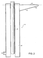
- FIG. 2 shows an alternative embodiment of the invention.
- Device 26 comprises a tubular chamber 28 having an inlet 30 and an outlet 32.
- the outlet 32 projects outwardly and upwardly from the annular chamber 28.
- Apertures 34 are located on the lower surface of outlet 32 towards the end thereof. This has the advantage of minimising the pressure of the water located within the outlet 32 in the vicinity of the apertures 34 whilst water is not flowing through the device 26. Thus the chances of liquid being lost through the apertures 34 whilst liquid is not flowing through the device are reduced.
- the embodiment shown has an outlet 32 with a substantially horizontal upper wall 36. As indicated, the upper wall 36 is positioned slightly below the highest point of the chamber 28. This results in a small head of pressure in the outlet 32 ensuring that the outlet remains full of water. In alternative embodiments, the outlet could project higher than the highest point of the chamber.
- Figure 3 is a large-scale view of the top portion of the device 26 shown in figure 2 .
- the lamp 18 directly illuminates all of the internal surfaces of the outlet 32, without UV radiation escaping directly through the apertures 34. In the embodiment shown, this result is achieved simply by the size and position of the apertures 34 relative to the lamp 18 and the thickness of the wall of the outlet 32.
- Line 38 illustrates the path of UV radiation from a point on the lamp 38 substantially horizontally into the outlet 32. As shown, although the path 38 enters an aperture 34, it terminates on the inner wall of that aperture distal to the lamp 18. Thus UV radiation along path 38 cannot directly pass out of the device 26 through the apertures 34.
- Line 40 illustrates the path from the highest possible point of lamp 40 to the apertures 34. Even though the path 40 is angled more steeply into the apertures 34 than path 38, the path 40 still terminates on the inner surface of an aperture. Thus light from the lamp 18 travelling on path 40 cannot directly escape through the apertures 34.
- Path 42 shows the minimum angle needed for light to directly pass through the apertures 34. It can be seen that a user of the device cannot see through the apertures 34 to see the lamp 18.
- the device is preferably arranged so that there is no direct optical path to the lamp from outside the device even if the shower rose is removed.
- FIG. 4 shows a further embodiment of the invention comprising a wall-mounted shower unit 44.
- the unit 44 has a plastic casing 46 through which protrudes a shower rose 48.
- a flexible water inlet hose 50 is connected to the base of the unit 44 using a snap fit connector 52.
- FIG. 5 shows the unit 44 with the front casing 46 hinged open.
- the components of the device 44 comprise a sterilisation tube 56 containing a UV lamp.
- the tube 56 has an outlet portion 58 projecting therefrom which terminates in the shower rose 48.
- the casing 46 has an aperture through which the shower rose 48 projects when the casing 46 is in a closed position.
- the shower rose 48 is attached to the outlet portion 58 in such a way as to prevent the removal of the rose 48 whilst the casing 46 is closed.
- the casing 46 must be opened before the rose 48 can be removed. As will be described below, this prevents the accidental exposure of a user to UV radiation by the unit.
- a control unit 60 comprises electronic components which control the functioning of the unit. On the control unit 60 there is provided a sensor 62 which detects whether the casing 46 is opened or closed. When the casing 46 is opened, the sensor 62 is activated and the UV lamp is automatically switched off.
- the inlet pipe 72 leading from the connector 52 to the base of the sterilisation tube 56.
- the inlet pipe 72 is provided with a shut-off valve 74 which is controlled by the control unit 60.
- the control unit 60 activates the valve 74 to shut off the flow of liquid through the device. This prevents potentially unsterilised water from leaving the device 44.
- the valve 74 is a pulse latching valve which operates via a magnetic pulse.
- the valve 74 is activated by a capacitor. Thus, in the event of power failure, the capacitor powers the valve 74, allowing it to close, again preventing the flow of potentially unsterilised water through unit 44.
- the warning light 68 is activated to warn the user of this fact.
- the red indicator light 64 When the device is initially switched on, the red indicator light 64 is activated to indicated that the unit is powered but not yet operational.
- the control unit 60 activates the UV lamp in the sterilisation tube 56 but prevents water from flowing through the unit for a predetermined period of two minutes. Depending on the circumstances, other periods of time could be used. This delay is provided to allow the UV lamp to reach optimum working conditions and to give sufficient time for the sterilisation of the water already contained within the unit.
- the red light 64 Once the predetermined period of time ends, the red light 64 is turned off and the green light 66 is turned on to show that normal operating conditions have been reached.
- the control unit 60 then opens the valve 74, allowing water to flow through the device.
- a photosensor 70 which detects the emission of UV radiation from the UV lamp within the sterilisation tube 56. If the lamp fails or if the level of radiation has dropped below a predetermined safe minimum value, the control unit 60 closes the valve 74 and turns off the UV lamp. The red light 64 is then turned on in a flashing mode to alert the user of the situation. The UV lamp can then be replaced or repaired in order for the unit to become operational again.
- a user may wish to rinse a fitting such as a bath.
- the flexible hose 50 may be disconnected via the connector 52 from the unit 44 and used to rinse such a fitting.
- micro-organisms such as legionella are normally only harmful when present in a mist or aerosol of water droplets, the use of a water hose in this way should not pose any risk.
- the water inlet for the unit 44 could be provided at the back of the device.
- the user would be presented with only the unit 44 mounted on a wall without any visible external water connections.
- the bulk of the unit is located within a cavity behind a wall or other such configurations such that only the water outlet or shower rose is visible.
- the device, or parts thereof may be constructed from materials other than stainless steel, including metals such as copper and plastics such as ABS, nylon and u-PVC.
Landscapes
- Health & Medical Sciences (AREA)
- Engineering & Computer Science (AREA)
- Life Sciences & Earth Sciences (AREA)
- Water Supply & Treatment (AREA)
- Chemical & Material Sciences (AREA)
- Hydrology & Water Resources (AREA)
- Public Health (AREA)
- General Engineering & Computer Science (AREA)
- Toxicology (AREA)
- Physics & Mathematics (AREA)
- Animal Behavior & Ethology (AREA)
- General Health & Medical Sciences (AREA)
- Mechanical Engineering (AREA)
- Veterinary Medicine (AREA)
- Combustion & Propulsion (AREA)
- Thermal Sciences (AREA)
- Epidemiology (AREA)
- Environmental & Geological Engineering (AREA)
- Organic Chemistry (AREA)
- Physical Water Treatments (AREA)
- Bathtubs, Showers, And Their Attachments (AREA)
- Apparatus For Disinfection Or Sterilisation (AREA)
- Nozzles (AREA)
- Domestic Plumbing Installations (AREA)
Claims (14)
- Eine Vorrichtung (2,26,44) zum Sterilisieren eines Wasserstroms, wobei die Vorrichtung einen Einlass (6,30) durch welchen das Wasser in die Vorrichtung eintritt, eine Quelle für Ultraviolettstrahlung (18) und eine Sterilisationszone (4,28,56) mit einem Auslassabschnitt (10,32,58), welcher einen Duschkopf (48) aufweist, der mindestens eine Öffnung (16,34) besitzt, durch die das Wasser die Vorrichtung (2,26,44) verlässt, aufweist, wobei die Sterilisationszone (4,28,56) so angeordnet ist, dass sie durch die Quelle für Ultraviolettstrahlung (18) so bestrahlt wird, dass alle internen Oberflächen des Auslassabschnittes (10,32,58) durch die Quelle für Ultraviolettstrahlung (18) direkt bestrahlt werden, dadurch gekennzeichnet, dass die Quelle für Ultraviolettstrahlung (18) und die mindestens eine Öffnung (16,34) so angeordnet sind, dass keine Ultraviolettstrahlung direkt von der Quelle für Ultraviolettstrahlung (18) durch die mindestens eine Öffnung (16,34) des Duschkopfes (48) übertragen wird.
- Eine Vorrichtung (2,26,44) gemäß Anspruch 1, wobei der Auslassabschnitt (10,32,58) ein längliches Volumen definiert, das sich von der Quelle für Ultraviolettstrahlung (18) weg erstreckt.
- Eine Vorrichtung (2,26,44) gemäß Anspruch 1 oder 2, wobei die mindestens eine Öffnung (16,34) zu einem offenen Luftraum führt.
- Eine Vorrichtung (2,26,44) gemäß Anspruch 1, 2 oder 3, wobei der Auslassabschnitt (10,32,58) sich kontinuierlich zu der Quelle für Ultraviolettstrahlung (18) erstreckt.
- Eine Vorrichtung (2,26,44) gemäß einem der vorstehenden Ansprüche, wobei die Vorrichtung (2,26,44) ferner ein Gehäuse (46) aufweist, das ein Entfernen des Duschkopfes (48) verhindert.
- Eine Vorrichtung (2,26,44) gemäß einem der vorstehenden Ansprüche, die Edelstahl aufweist.
- Eine Vorrichtung (2,26,44) gemäß einem der vorstehenden Ansprüche, wobei die Quelle für Ultraviolettstrahlung (18) eine Ultraviolettlampe ist.
- Eine Vorrichtung (2,26,44) gemäß einem der vorstehenden Ansprüche, wobei die Quelle für Ultraviolettstrahlung (18) in einem Quarzgehäuse (20) aufgenommen ist.
- Eine Vorrichtung (2,26,44) gemäß einem der vorstehenden Ansprüche, die im Einsatz so positioniert ist, dass der Auslassabschnitt (10,32,58) mindestens teilweise von dem Rest der Vorrichtung (2,26,44) nach oben vorsteht.
- Eine Vorrichtung (2,26,44) gemäß einem der vorstehenden Ansprüche, die so angeordnet ist, dass die Quelle für Ultraviolettstrahlung (18) abgeschaltet ist bzw. wird, wenn die Vorrichtung (2,26,44) geöffnet ist bzw. wird.
- Eine Vorrichtung (2,26,44) gemäß einem der vorstehenden Ansprüche, wobei die Vorrichtung (2,26,44) ein Mittel zum Abschalten des Wasserstroms aufweist, wenn die Quelle für Ultraviolettstrahlung (18) aus ist.
- Eine Vorrichtung (2,26,44) gemäß Anspruch 11, wobei das Mittel zum Abschalten des Wasserstroms ein einrastendes Pulsventil aufweist.
- Eine Vorrichtung (2,26,44) gemäß Anspruch 11 oder 12, wobei das Mittel zum Abschalten des Wasserstroms durch einen Kondensator mit Energie versorgt ist.
- Eine Vorrichtung (2,26,44) gemäß einem vorstehenden Anspruch, ferner mit Mitteln zum Verhindern eines Wasserstroms durch die Vorrichtung (2,26,44) für eine vorbestimmte Zeitspanne, nachdem die Quelle für Ultraviolettstrahlung (18) aktiviert ist bzw. wird.
Priority Applications (1)
| Application Number | Priority Date | Filing Date | Title |
|---|---|---|---|
| EP07075887A EP1872801A3 (de) | 2003-02-22 | 2004-02-20 | Vorrichtung zur entkeimung von flüssigkeiten |
Applications Claiming Priority (3)
| Application Number | Priority Date | Filing Date | Title |
|---|---|---|---|
| GB0304070 | 2003-02-22 | ||
| GB0304070A GB2384238B (en) | 2003-02-22 | 2003-02-22 | Improvements in or relating to a device for sterilising a fluid |
| PCT/GB2004/000672 WO2004073754A1 (en) | 2003-02-22 | 2004-02-20 | A device for sterilising a fluid |
Related Child Applications (2)
| Application Number | Title | Priority Date | Filing Date |
|---|---|---|---|
| EP07075887A Division EP1872801A3 (de) | 2003-02-22 | 2004-02-20 | Vorrichtung zur entkeimung von flüssigkeiten |
| EP07075887.5 Division-Into | 2007-10-16 |
Publications (2)
| Publication Number | Publication Date |
|---|---|
| EP1599234A1 EP1599234A1 (de) | 2005-11-30 |
| EP1599234B1 true EP1599234B1 (de) | 2013-12-25 |
Family
ID=9953482
Family Applications (2)
| Application Number | Title | Priority Date | Filing Date |
|---|---|---|---|
| EP07075887A Withdrawn EP1872801A3 (de) | 2003-02-22 | 2004-02-20 | Vorrichtung zur entkeimung von flüssigkeiten |
| EP04713108.1A Expired - Lifetime EP1599234B1 (de) | 2003-02-22 | 2004-02-20 | Vorrichtung zum sterilisieren von wasser |
Family Applications Before (1)
| Application Number | Title | Priority Date | Filing Date |
|---|---|---|---|
| EP07075887A Withdrawn EP1872801A3 (de) | 2003-02-22 | 2004-02-20 | Vorrichtung zur entkeimung von flüssigkeiten |
Country Status (10)
| Country | Link |
|---|---|
| US (1) | US7566885B2 (de) |
| EP (2) | EP1872801A3 (de) |
| JP (1) | JP4417374B2 (de) |
| AU (1) | AU2004212760B2 (de) |
| CA (1) | CA2516734C (de) |
| ES (1) | ES2453296T3 (de) |
| GB (1) | GB2384238B (de) |
| NZ (1) | NZ542299A (de) |
| WO (1) | WO2004073754A1 (de) |
| ZA (1) | ZA200507357B (de) |
Families Citing this family (28)
| Publication number | Priority date | Publication date | Assignee | Title |
|---|---|---|---|---|
| ITFI20030284A1 (it) * | 2003-11-05 | 2005-05-06 | Pietro Castellacci | Apparecchiatura per la sterilizzazione, in specie antibatterica,dell'acqua in installazioni sanitarie e simili |
| GB0406727D0 (en) * | 2004-03-25 | 2004-04-28 | Snowball Malcolm R | Fluid treatment system |
| US8002881B2 (en) * | 2005-03-16 | 2011-08-23 | Oy Halton Group Ltd. | Fume treatment method and apparatus using ultraviolet light to degrade contaminants |
| DE102005015129B4 (de) * | 2005-03-31 | 2006-11-30 | Schluttig, Alexander, Dr. | Hygiene-Waschplatz |
| CN1977978B (zh) * | 2005-12-01 | 2011-07-06 | 福建新大陆环保科技有限公司 | 一种开放式水渠辐射消毒系统 |
| FR2924025B1 (fr) * | 2007-11-27 | 2011-05-13 | Rc Lux | Dispositif de securisation de liquide par rayonnements ultraviolets au point d'utilisation et procede de securisation de liquide |
| FR2927068B1 (fr) * | 2008-02-05 | 2012-12-07 | Lvmh Rech | Dispositif de distribution pour produit fluide et procede de distribution |
| DE102008002727B4 (de) | 2008-06-27 | 2020-12-17 | Brita Gmbh | Vorrichtung zur Behandlung von Wasser, insbesondere Filtervorrichtung, und Kartusche |
| DE102008040335B4 (de) | 2008-07-10 | 2013-05-08 | Brita Gmbh | Vorrichtung zur Entkeimung von Wasser und Verwendung derselben |
| DE102008040336A1 (de) * | 2008-07-10 | 2010-05-12 | Brita Gmbh | Vorrichtung zur Entkeimung von Wasser und Verwendung derselben |
| JP2010214241A (ja) * | 2009-03-13 | 2010-09-30 | Panasonic Electric Works Co Ltd | 浄水器 |
| FR2945527B1 (fr) | 2009-05-15 | 2011-07-15 | Rc Lux | Procede de fonctionnement et de gestion d'un distributeur d'un liquide et distributeur d'un liquide. |
| US8496610B2 (en) * | 2009-06-23 | 2013-07-30 | David J. Levenson | Device for flow-through ultraviolet light decontamination of microbial contaminants |
| US9320880B2 (en) | 2009-06-23 | 2016-04-26 | Djlm Innovations, Llc | Device for flow-through ultraviolet light decontamination of microbial contaminants |
| DE202011000503U1 (de) * | 2011-03-08 | 2011-10-14 | Brita Gmbh | Auslassstück für eine Vorrichtung zum Aufbereiten einer Flüssigkeit |
| TWD148182S1 (zh) | 2011-04-01 | 2012-07-11 | 布利塔有限公司 | 紫外線輻射裝置 |
| WO2013071941A1 (de) * | 2011-11-17 | 2013-05-23 | Alexander Schluttig | Vorrichtung und verfahren zur herstellung keimfreien wassers mittels eines querstrom-flüssigkeitssterilfiltes |
| GB201208224D0 (en) * | 2012-05-10 | 2012-06-20 | Helmore Ian S | A device for sterilising water |
| TWI509174B (zh) * | 2013-04-25 | 2015-11-21 | Univ Shu Te | 多功能出水裝置 |
| USD765263S1 (en) * | 2015-03-04 | 2016-08-30 | Ryan Sheldon NELSON | Sanitation device for dental accessories |
| DE102015006278B4 (de) | 2015-05-15 | 2021-09-09 | Alexander Schluttig | Selbstdesinfizierender Geruchsverschluss |
| JP2019516514A (ja) | 2016-05-24 | 2019-06-20 | シグニファイ ホールディング ビー ヴィ | 消費者装置内のuvモジュール |
| WO2018097789A1 (en) * | 2016-11-25 | 2018-05-31 | Orbital Systems Ab | Sensor system for a system allowing for purification and recycling of water or separation of water |
| IL249680B (en) * | 2016-12-21 | 2018-05-31 | Zabari Lidor | Self-sealing and disinfecting shower head |
| WO2019055348A1 (en) | 2017-09-12 | 2019-03-21 | A.O. Smith Corporation | WATER TAP CONTAINING DISINFECTION ELEMENTS |
| GB201900016D0 (en) * | 2019-01-02 | 2019-02-13 | Dyson Technology Ltd | Air treatment apparatus |
| GB201900022D0 (en) * | 2019-01-02 | 2019-02-13 | Dyson Technology Ltd | Air treatment apparatus |
| CN114857278A (zh) * | 2022-07-05 | 2022-08-05 | 至善时代智能科技(北京)有限公司 | 一种杀菌水龙头 |
Family Cites Families (24)
| Publication number | Priority date | Publication date | Assignee | Title |
|---|---|---|---|---|
| US3250294A (en) * | 1962-09-07 | 1966-05-10 | American Brake Shoe Co | Valve and control circuit therefor |
| DE19618771C2 (de) | 1996-05-10 | 2000-10-19 | Karl F Massholder | Wasserentnahmearmatur |
| US4102645A (en) * | 1976-06-23 | 1978-07-25 | Refreshment Machinery Incorporated | Sterilization apparatus |
| JPS59136188A (ja) * | 1983-01-27 | 1984-08-04 | Houshin Kagaku Sangiyoushiyo:Kk | 流体末端汚染防止装置 |
| GB2175777A (en) * | 1985-05-24 | 1986-12-03 | Still & Sons Ltd W M | Improvements in and relating to water purifiers |
| US4672613A (en) | 1985-11-01 | 1987-06-09 | Cipher Data Products, Inc. | System for transferring digital data between a host device and a recording medium |
| JPH03177710A (ja) | 1989-12-06 | 1991-08-01 | Inax Corp | 給湯機 |
| US5288412A (en) * | 1992-01-09 | 1994-02-22 | Voorhees Michael T | Gray water processing system |
| US6497840B1 (en) * | 1992-10-09 | 2002-12-24 | Richard P. Palestro | Ultraviolet germicidal system |
| US5393419A (en) * | 1993-02-10 | 1995-02-28 | Amway Corporation | Ultraviolet lamp assembly for water purification |
| JPH0866677A (ja) * | 1994-08-26 | 1996-03-12 | Hajime Honda | 紫外線殺菌蛇口 |
| JPH09173233A (ja) | 1995-12-27 | 1997-07-08 | Janome Sewing Mach Co Ltd | 浴水浄化循環装置 |
| AU1555597A (en) * | 1996-02-23 | 1997-09-10 | Katadyn Produkte Ag | Modular water-treatment apparatus |
| DE19639802B4 (de) * | 1996-09-27 | 2008-06-12 | Hansgrohe Ag | Sanitäre Auslaufeinrichtung |
| JPH10296246A (ja) | 1997-04-25 | 1998-11-10 | Bridgestone Corp | 浴水循環装置 |
| US6486419B2 (en) * | 1998-01-09 | 2002-11-26 | Ricoh Company, Ltd. | Multifunctional image forming apparatus having a covered main power switch |
| US6127671A (en) | 1998-05-28 | 2000-10-03 | Arichell Technologies, Inc. | Directional object sensor for automatic flow controller |
| JP2000084545A (ja) | 1998-09-11 | 2000-03-28 | Sanyo Electric Co Ltd | 浴水循環浄化装置 |
| JP2000201569A (ja) | 1999-01-18 | 2000-07-25 | Toshiba Lighting & Technology Corp | 水浄化装置および水槽装置 |
| NL1012389C1 (nl) * | 1999-06-18 | 2000-12-19 | Remmen Uv Techniek Van | Ultraviolette lamp en douchekop voorzien van een lamp. |
| JP4527849B2 (ja) | 2000-05-29 | 2010-08-18 | 東西化学産業株式会社 | 液体吐出装置 |
| DE10157355A1 (de) | 2000-11-24 | 2002-06-06 | Jos Weber Gmbh & Co Kg Kunstst | Vorrichtung zur Desinfektion von Brauchwasser mittels UV-Strahlung |
| DE20105341U1 (de) | 2001-03-26 | 2002-08-01 | Müller, Hans, 67305 Ramsen | Vorrichtung zum Desinfizieren und Entkeimen von Wasser sowie Dusch- oder Brausekopf mit einer derartigen Vorrichtung |
| JP2002301379A (ja) | 2001-04-09 | 2002-10-15 | Fuji Kihan:Kk | 光触媒成品の効率的使用方法及び前記方法を利用した光触媒成品の集合体 |
-
2003
- 2003-02-22 GB GB0304070A patent/GB2384238B/en not_active Expired - Fee Related
-
2004
- 2004-02-20 EP EP07075887A patent/EP1872801A3/de not_active Withdrawn
- 2004-02-20 EP EP04713108.1A patent/EP1599234B1/de not_active Expired - Lifetime
- 2004-02-20 WO PCT/GB2004/000672 patent/WO2004073754A1/en not_active Ceased
- 2004-02-20 AU AU2004212760A patent/AU2004212760B2/en not_active Ceased
- 2004-02-20 JP JP2006502301A patent/JP4417374B2/ja not_active Expired - Fee Related
- 2004-02-20 US US10/546,488 patent/US7566885B2/en not_active Expired - Fee Related
- 2004-02-20 ES ES04713108.1T patent/ES2453296T3/es not_active Expired - Lifetime
- 2004-02-20 CA CA002516734A patent/CA2516734C/en not_active Expired - Fee Related
- 2004-02-20 NZ NZ542299A patent/NZ542299A/en not_active IP Right Cessation
-
2005
- 2005-09-13 ZA ZA200507357A patent/ZA200507357B/en unknown
Also Published As
| Publication number | Publication date |
|---|---|
| ES2453296T3 (es) | 2014-04-07 |
| GB0304070D0 (en) | 2003-03-26 |
| GB2384238B (en) | 2003-12-03 |
| EP1872801A2 (de) | 2008-01-02 |
| CA2516734C (en) | 2008-05-20 |
| JP2006518236A (ja) | 2006-08-10 |
| ZA200507357B (en) | 2006-09-27 |
| EP1599234A1 (de) | 2005-11-30 |
| AU2004212760B2 (en) | 2006-10-12 |
| US20060192137A1 (en) | 2006-08-31 |
| AU2004212760A1 (en) | 2004-09-02 |
| EP1872801A3 (de) | 2008-02-27 |
| CA2516734A1 (en) | 2004-09-02 |
| US7566885B2 (en) | 2009-07-28 |
| GB2384238A (en) | 2003-07-23 |
| WO2004073754A1 (en) | 2004-09-02 |
| NZ542299A (en) | 2006-10-27 |
| JP4417374B2 (ja) | 2010-02-17 |
Similar Documents
| Publication | Publication Date | Title |
|---|---|---|
| US7566885B2 (en) | Device for sterilizing a fluid | |
| DK2323952T3 (en) | A disinfection device with the power supply means and the liquid outlet | |
| EP2707333B1 (de) | Ozonbasierte desinfektionsvorrichtung mit einem durchflusssensor | |
| EP2706864B1 (de) | Ozonbasierte desinfektionsvorrichtung und mischer hierfür | |
| CN111094669B (zh) | 水消毒方法和用于水消毒方法的出水组件 | |
| US20100247374A1 (en) | Device for making a liquid safe by ultraviolet radiation at the dispensing point and method for making a liquid safe | |
| US20160213444A1 (en) | Device and method for sanitizing gas and water | |
| CA2920097A1 (en) | Device and method for sanitizing gas and water | |
| JP4832298B2 (ja) | 再処理装置用の流体流出/空気補充アセンブリ | |
| JPH0866677A (ja) | 紫外線殺菌蛇口 | |
| CN207016521U (zh) | 杀菌装置、水箱及通用杀菌装置 | |
| US20150114911A1 (en) | Device for sterilising water | |
| JPH10338952A (ja) | 無菌水供給装置 | |
| CN109231351A (zh) | 水处理系统及其控制方法及杀菌装置 | |
| JPH0646550Y2 (ja) | 殺菌水装置における殺菌灯付蛇口 | |
| KR920008810Y1 (ko) | 음료수 배출콕의 자외선 살균장치 | |
| JP3180140B2 (ja) | 殺菌装置 | |
| WO2026039865A1 (en) | Fluid sterilisation device | |
| JPS5920394Y2 (ja) | 殺菌水製造ユニツト | |
| CN213630759U (zh) | 具有紫外线杀菌功能的加湿器 | |
| EP1208064A1 (de) | Verbesserungen an wassererzeugungsvorrichtungen |
Legal Events
| Date | Code | Title | Description |
|---|---|---|---|
| PUAI | Public reference made under article 153(3) epc to a published international application that has entered the european phase |
Free format text: ORIGINAL CODE: 0009012 |
|
| 17P | Request for examination filed |
Effective date: 20050915 |
|
| AK | Designated contracting states |
Kind code of ref document: A1 Designated state(s): AT BE BG CH CY CZ DE DK EE ES FI FR GB GR HU IE IT LI LU MC NL PT RO SE SI SK TR |
|
| AX | Request for extension of the european patent |
Extension state: AL LT LV MK |
|
| DAX | Request for extension of the european patent (deleted) | ||
| REG | Reference to a national code |
Ref country code: HK Ref legal event code: DE Ref document number: 1084611 Country of ref document: HK |
|
| APBN | Date of receipt of notice of appeal recorded |
Free format text: ORIGINAL CODE: EPIDOSNNOA2E |
|
| APBR | Date of receipt of statement of grounds of appeal recorded |
Free format text: ORIGINAL CODE: EPIDOSNNOA3E |
|
| APAF | Appeal reference modified |
Free format text: ORIGINAL CODE: EPIDOSCREFNE |
|
| APBT | Appeal procedure closed |
Free format text: ORIGINAL CODE: EPIDOSNNOA9E |
|
| GRAP | Despatch of communication of intention to grant a patent |
Free format text: ORIGINAL CODE: EPIDOSNIGR1 |
|
| RTI1 | Title (correction) |
Free format text: A DEVICE FOR STERILISING WATER |
|
| GRAS | Grant fee paid |
Free format text: ORIGINAL CODE: EPIDOSNIGR3 |
|
| RBV | Designated contracting states (corrected) |
Designated state(s): AT BE BG CH CY CZ DE DK EE ES FI FR GR HU IE IT LI LU MC NL PT RO SE SI SK TR |
|
| GRAA | (expected) grant |
Free format text: ORIGINAL CODE: 0009210 |
|
| AK | Designated contracting states |
Kind code of ref document: B1 Designated state(s): AT BE BG CH CY CZ DE DK EE ES FI FR GR HU IE IT LI LU MC NL PT RO SE SI SK TR |
|
| REG | Reference to a national code |
Ref country code: CH Ref legal event code: EP |
|
| REG | Reference to a national code |
Ref country code: AT Ref legal event code: REF Ref document number: 646201 Country of ref document: AT Kind code of ref document: T Effective date: 20140115 |
|
| REG | Reference to a national code |
Ref country code: IE Ref legal event code: FG4D |
|
| REG | Reference to a national code |
Ref country code: DE Ref legal event code: R096 Ref document number: 602004044066 Country of ref document: DE Effective date: 20140220 |
|
| REG | Reference to a national code |
Ref country code: NL Ref legal event code: T3 |
|
| REG | Reference to a national code |
Ref country code: ES Ref legal event code: FG2A Ref document number: 2453296 Country of ref document: ES Kind code of ref document: T3 Effective date: 20140407 |
|
| PG25 | Lapsed in a contracting state [announced via postgrant information from national office to epo] |
Ref country code: SE Free format text: LAPSE BECAUSE OF FAILURE TO SUBMIT A TRANSLATION OF THE DESCRIPTION OR TO PAY THE FEE WITHIN THE PRESCRIBED TIME-LIMIT Effective date: 20131225 Ref country code: FI Free format text: LAPSE BECAUSE OF FAILURE TO SUBMIT A TRANSLATION OF THE DESCRIPTION OR TO PAY THE FEE WITHIN THE PRESCRIBED TIME-LIMIT Effective date: 20131225 |
|
| REG | Reference to a national code |
Ref country code: AT Ref legal event code: MK05 Ref document number: 646201 Country of ref document: AT Kind code of ref document: T Effective date: 20131225 |
|
| PG25 | Lapsed in a contracting state [announced via postgrant information from national office to epo] |
Ref country code: BE Free format text: LAPSE BECAUSE OF FAILURE TO SUBMIT A TRANSLATION OF THE DESCRIPTION OR TO PAY THE FEE WITHIN THE PRESCRIBED TIME-LIMIT Effective date: 20131225 Ref country code: EE Free format text: LAPSE BECAUSE OF FAILURE TO SUBMIT A TRANSLATION OF THE DESCRIPTION OR TO PAY THE FEE WITHIN THE PRESCRIBED TIME-LIMIT Effective date: 20131225 |
|
| PGFP | Annual fee paid to national office [announced via postgrant information from national office to epo] |
Ref country code: MC Payment date: 20140410 Year of fee payment: 11 |
|
| PG25 | Lapsed in a contracting state [announced via postgrant information from national office to epo] |
Ref country code: SK Free format text: LAPSE BECAUSE OF FAILURE TO SUBMIT A TRANSLATION OF THE DESCRIPTION OR TO PAY THE FEE WITHIN THE PRESCRIBED TIME-LIMIT Effective date: 20131225 Ref country code: RO Free format text: LAPSE BECAUSE OF FAILURE TO SUBMIT A TRANSLATION OF THE DESCRIPTION OR TO PAY THE FEE WITHIN THE PRESCRIBED TIME-LIMIT Effective date: 20131225 Ref country code: CZ Free format text: LAPSE BECAUSE OF FAILURE TO SUBMIT A TRANSLATION OF THE DESCRIPTION OR TO PAY THE FEE WITHIN THE PRESCRIBED TIME-LIMIT Effective date: 20131225 Ref country code: AT Free format text: LAPSE BECAUSE OF FAILURE TO SUBMIT A TRANSLATION OF THE DESCRIPTION OR TO PAY THE FEE WITHIN THE PRESCRIBED TIME-LIMIT Effective date: 20131225 Ref country code: PT Free format text: LAPSE BECAUSE OF FAILURE TO SUBMIT A TRANSLATION OF THE DESCRIPTION OR TO PAY THE FEE WITHIN THE PRESCRIBED TIME-LIMIT Effective date: 20140428 Ref country code: CY Free format text: LAPSE BECAUSE OF FAILURE TO SUBMIT A TRANSLATION OF THE DESCRIPTION OR TO PAY THE FEE WITHIN THE PRESCRIBED TIME-LIMIT Effective date: 20131225 |
|
| PGFP | Annual fee paid to national office [announced via postgrant information from national office to epo] |
Ref country code: FR Payment date: 20140409 Year of fee payment: 11 Ref country code: DE Payment date: 20140417 Year of fee payment: 11 Ref country code: IT Payment date: 20140416 Year of fee payment: 11 Ref country code: NL Payment date: 20140410 Year of fee payment: 11 |
|
| REG | Reference to a national code |
Ref country code: DE Ref legal event code: R097 Ref document number: 602004044066 Country of ref document: DE |
|
| PG25 | Lapsed in a contracting state [announced via postgrant information from national office to epo] |
Ref country code: LU Free format text: LAPSE BECAUSE OF FAILURE TO SUBMIT A TRANSLATION OF THE DESCRIPTION OR TO PAY THE FEE WITHIN THE PRESCRIBED TIME-LIMIT Effective date: 20140220 |
|
| REG | Reference to a national code |
Ref country code: CH Ref legal event code: PL |
|
| PG25 | Lapsed in a contracting state [announced via postgrant information from national office to epo] |
Ref country code: LI Free format text: LAPSE BECAUSE OF NON-PAYMENT OF DUE FEES Effective date: 20140228 Ref country code: CH Free format text: LAPSE BECAUSE OF NON-PAYMENT OF DUE FEES Effective date: 20140228 Ref country code: DK Free format text: LAPSE BECAUSE OF FAILURE TO SUBMIT A TRANSLATION OF THE DESCRIPTION OR TO PAY THE FEE WITHIN THE PRESCRIBED TIME-LIMIT Effective date: 20131225 |
|
| PLBE | No opposition filed within time limit |
Free format text: ORIGINAL CODE: 0009261 |
|
| STAA | Information on the status of an ep patent application or granted ep patent |
Free format text: STATUS: NO OPPOSITION FILED WITHIN TIME LIMIT |
|
| 26N | No opposition filed |
Effective date: 20140926 |
|
| REG | Reference to a national code |
Ref country code: DE Ref legal event code: R097 Ref document number: 602004044066 Country of ref document: DE Effective date: 20140926 |
|
| PG25 | Lapsed in a contracting state [announced via postgrant information from national office to epo] |
Ref country code: SI Free format text: LAPSE BECAUSE OF FAILURE TO SUBMIT A TRANSLATION OF THE DESCRIPTION OR TO PAY THE FEE WITHIN THE PRESCRIBED TIME-LIMIT Effective date: 20131225 |
|
| REG | Reference to a national code |
Ref country code: DE Ref legal event code: R119 Ref document number: 602004044066 Country of ref document: DE |
|
| REG | Reference to a national code |
Ref country code: NL Ref legal event code: V1 Effective date: 20150901 |
|
| REG | Reference to a national code |
Ref country code: HK Ref legal event code: WD Ref document number: 1084611 Country of ref document: HK |
|
| PG25 | Lapsed in a contracting state [announced via postgrant information from national office to epo] |
Ref country code: NL Free format text: LAPSE BECAUSE OF NON-PAYMENT OF DUE FEES Effective date: 20150901 |
|
| PG25 | Lapsed in a contracting state [announced via postgrant information from national office to epo] |
Ref country code: MC Free format text: LAPSE BECAUSE OF NON-PAYMENT OF DUE FEES Effective date: 20150302 |
|
| REG | Reference to a national code |
Ref country code: FR Ref legal event code: ST Effective date: 20151030 |
|
| PG25 | Lapsed in a contracting state [announced via postgrant information from national office to epo] |
Ref country code: IT Free format text: LAPSE BECAUSE OF NON-PAYMENT OF DUE FEES Effective date: 20150220 |
|
| PG25 | Lapsed in a contracting state [announced via postgrant information from national office to epo] |
Ref country code: DE Free format text: LAPSE BECAUSE OF NON-PAYMENT OF DUE FEES Effective date: 20150901 |
|
| PG25 | Lapsed in a contracting state [announced via postgrant information from national office to epo] |
Ref country code: FR Free format text: LAPSE BECAUSE OF NON-PAYMENT OF DUE FEES Effective date: 20150302 |
|
| PGFP | Annual fee paid to national office [announced via postgrant information from national office to epo] |
Ref country code: IE Payment date: 20160224 Year of fee payment: 13 |
|
| PG25 | Lapsed in a contracting state [announced via postgrant information from national office to epo] |
Ref country code: BG Free format text: LAPSE BECAUSE OF FAILURE TO SUBMIT A TRANSLATION OF THE DESCRIPTION OR TO PAY THE FEE WITHIN THE PRESCRIBED TIME-LIMIT Effective date: 20131225 |
|
| PG25 | Lapsed in a contracting state [announced via postgrant information from national office to epo] |
Ref country code: GR Free format text: LAPSE BECAUSE OF FAILURE TO SUBMIT A TRANSLATION OF THE DESCRIPTION OR TO PAY THE FEE WITHIN THE PRESCRIBED TIME-LIMIT Effective date: 20140326 |
|
| PG25 | Lapsed in a contracting state [announced via postgrant information from national office to epo] |
Ref country code: HU Free format text: LAPSE BECAUSE OF FAILURE TO SUBMIT A TRANSLATION OF THE DESCRIPTION OR TO PAY THE FEE WITHIN THE PRESCRIBED TIME-LIMIT; INVALID AB INITIO Effective date: 20040220 Ref country code: TR Free format text: LAPSE BECAUSE OF FAILURE TO SUBMIT A TRANSLATION OF THE DESCRIPTION OR TO PAY THE FEE WITHIN THE PRESCRIBED TIME-LIMIT Effective date: 20131225 |
|
| PGFP | Annual fee paid to national office [announced via postgrant information from national office to epo] |
Ref country code: ES Payment date: 20140328 Year of fee payment: 11 |
|
| REG | Reference to a national code |
Ref country code: ES Ref legal event code: FD2A Effective date: 20160930 |
|
| PG25 | Lapsed in a contracting state [announced via postgrant information from national office to epo] |
Ref country code: ES Free format text: LAPSE BECAUSE OF NON-PAYMENT OF DUE FEES Effective date: 20150221 |
|
| REG | Reference to a national code |
Ref country code: IE Ref legal event code: MM4A |
|
| PG25 | Lapsed in a contracting state [announced via postgrant information from national office to epo] |
Ref country code: IE Free format text: LAPSE BECAUSE OF NON-PAYMENT OF DUE FEES Effective date: 20170220 |