EP1598774B1 - Steuerung von verpackten Produkten - Google Patents
Steuerung von verpackten Produkten Download PDFInfo
- Publication number
- EP1598774B1 EP1598774B1 EP05104295A EP05104295A EP1598774B1 EP 1598774 B1 EP1598774 B1 EP 1598774B1 EP 05104295 A EP05104295 A EP 05104295A EP 05104295 A EP05104295 A EP 05104295A EP 1598774 B1 EP1598774 B1 EP 1598774B1
- Authority
- EP
- European Patent Office
- Prior art keywords
- tag
- information
- module
- container
- identification
- Prior art date
- Legal status (The legal status is an assumption and is not a legal conclusion. Google has not performed a legal analysis and makes no representation as to the accuracy of the status listed.)
- Ceased
Links
Images


Classifications
-
- G—PHYSICS
- G06—COMPUTING OR CALCULATING; COUNTING
- G06K—GRAPHICAL DATA READING; PRESENTATION OF DATA; RECORD CARRIERS; HANDLING RECORD CARRIERS
- G06K19/00—Record carriers for use with machines and with at least a part designed to carry digital markings
- G06K19/06—Record carriers for use with machines and with at least a part designed to carry digital markings characterised by the kind of the digital marking, e.g. shape, nature, code
- G06K19/067—Record carriers with conductive marks, printed circuits or semiconductor circuit elements, e.g. credit or identity cards also with resonating or responding marks without active components
- G06K19/07—Record carriers with conductive marks, printed circuits or semiconductor circuit elements, e.g. credit or identity cards also with resonating or responding marks without active components with integrated circuit chips
- G06K19/077—Constructional details, e.g. mounting of circuits in the carrier
- G06K19/07749—Constructional details, e.g. mounting of circuits in the carrier the record carrier being capable of non-contact communication, e.g. constructional details of the antenna of a non-contact smart card
- G06K19/07798—Constructional details, e.g. mounting of circuits in the carrier the record carrier being capable of non-contact communication, e.g. constructional details of the antenna of a non-contact smart card part of the antenna or the integrated circuit being adapted for rupturing or breaking, e.g. record carriers functioning as sealing devices for detecting not-authenticated opening of containers
-
- G—PHYSICS
- G03—PHOTOGRAPHY; CINEMATOGRAPHY; ANALOGOUS TECHNIQUES USING WAVES OTHER THAN OPTICAL WAVES; ELECTROGRAPHY; HOLOGRAPHY
- G03G—ELECTROGRAPHY; ELECTROPHOTOGRAPHY; MAGNETOGRAPHY
- G03G15/00—Apparatus for electrographic processes using a charge pattern
- G03G15/06—Apparatus for electrographic processes using a charge pattern for developing
- G03G15/08—Apparatus for electrographic processes using a charge pattern for developing using a solid developer, e.g. powder developer
- G03G15/0822—Arrangements for preparing, mixing, supplying or dispensing developer
- G03G15/0863—Arrangements for preparing, mixing, supplying or dispensing developer provided with identifying means or means for storing process- or use parameters, e.g. an electronic memory
-
- G—PHYSICS
- G06—COMPUTING OR CALCULATING; COUNTING
- G06K—GRAPHICAL DATA READING; PRESENTATION OF DATA; RECORD CARRIERS; HANDLING RECORD CARRIERS
- G06K17/00—Methods or arrangements for effecting co-operative working between equipments covered by two or more of main groups G06K1/00 - G06K15/00, e.g. automatic card files incorporating conveying and reading operations
-
- G—PHYSICS
- G03—PHOTOGRAPHY; CINEMATOGRAPHY; ANALOGOUS TECHNIQUES USING WAVES OTHER THAN OPTICAL WAVES; ELECTROGRAPHY; HOLOGRAPHY
- G03G—ELECTROGRAPHY; ELECTROPHOTOGRAPHY; MAGNETOGRAPHY
- G03G2215/00—Apparatus for electrophotographic processes
- G03G2215/06—Developing structures, details
- G03G2215/066—Toner cartridge or other attachable and detachable container for supplying developer material to replace the used material
- G03G2215/0695—Toner cartridge or other attachable and detachable container for supplying developer material to replace the used material using identification means or means for storing process or use parameters
- G03G2215/0697—Toner cartridge or other attachable and detachable container for supplying developer material to replace the used material using identification means or means for storing process or use parameters being an electronically readable memory
Definitions
- the present invention relates to monitoring devices or modules packaged within a container.
- the present invention is particularly useful in inventory control.
- a barcode containing a model number or a serial number or other identifying indicia can be printed on a device or a package.
- An optical scanner connected to a tracking system can scan the barcode, so that the tracking system can determine the identity and location of the marked item.
- Such barcode systems rely on a "line of sight" access from the barcode reader to the barcode on the item being tracked.
- the tracking system can record various information pertaining to the location and status of the tracked item, the item tracked does not itself retain any information as to where it has been, or what processing steps have been performed on it.
- radio frequency transmitters have been applied to devices for tracking purposes. Such radio frequency transmitters contain information that they can transmit to a reader. The radio frequency transmitters do not require a "line of sight" access from the reader.
- Magnetic tags and sensors have also been demonstrated to track and verify the identity of products. Magnetic tags require close proximity between the information bearing tag and the sensor.
- US 6,351,621 B1 describes wireless interaction with memory associated with a replaceable module for office equipment.
- a removable module such as a marking material supply module or a marking device module
- a non-volatile memory chip which retains information about the cumulative use of the module and other performance-related data.
- the non-volatile memory is accessed through a wireless interface, such as an RF loop or IR detector, which is also associated with the module.
- the memory can be accessed, through wireless means, either by the printer or copier itself or by an external device.
- the wireless interface can also be used to access a memory which is attached to part which moves within the printer or copier, such as a roller or drum, thus avoiding the use of wire harnesses.
- a product and material information communication system particularly for use in manufacturing processes comprises a product package or support having an RFID tag including data memory means for storing at least a unique identification code for the product and at least dynamic and/or static data associated with characteristics of the product which are related to use of the product in an intended manufacturing process and an interrogator for retrieving the identification code and product characteristic information and providing such product information to process control equipment for optimizing the operation thereof.
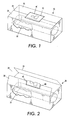
- Figure 1 shows a container incorporating an aspect of the present invention.
- Figure 2 shows the container of Figure 1 after the container has been opened.
- Figure 3 shows a different container incorporating an aspect of the present invention.
- Figure 4 shows an implementation of a tag forming an aspect of the present invention.
- Figure 5 shows the use of a portable tag writer or reader in accordance with an aspect of the present invention.
- Figure 6 shows the use of a fixed tag writer or reader in accordance with another aspect of the present invention.
- Figure 7 is a schematic illustration of a printing apparatus incorporating an aspect of the present invention.
- Figure 8 illustrates a container not according to the invention.
- Modules such as replacement parts or consumable elements for machinery or systems, are frequently stored and transported in containers.
- a particular implementation of the present invention will be described in the context of a consumable module for a printing apparatus, in particular a toner cartridge containing consumable toner.
- the cartridge is intended for insertion into a xerographic printing apparatus, in which toner is dispensed from the cartridge for use in the printing process.
- toner is dispensed from the cartridge for use in the printing process.
- module describes any item that can or is intended to be enclosed in a container for shipping, handling, or otherwise processing.
- a container 20 encloses a module, such as a replaceable toner cartridge 22 as shown in Figure 1 .
- a module such as a replaceable toner cartridge 22 as shown in Figure 1 .
- the container may also enclose packing material (not shown) to protect the enclosed module.
- the container may enclose multiple modules, which may be identical to one another, or may form a set of related modules.
- the container has an opening separation 24 that is adapted to expand upon opening the container.
- the opening separation is formed in the top surface by forming the top surface as two sections 26, 28 of container material that meet at a seam.
- the container with the opening separation expanded to open the container is shown in Figure 2 .
- the container 30 may be formed of a container body 31 with an open side and a separate piece of material to form a lid 32, having an opening separation 34 that extends around the perimeter of the lid, as shown in Figure 3 (without the enclosed module), where the edge of the lid meets the container body.
- Other types of opening separations might include a pull tab that tears the container material, or that has a line of perforations to permit the pull tab to separate to sections of the container.
- the container 20, 30 is formed of container material, such as cardboard, corrugated cardboard, polystyrene, or other commonly known materials.
- An electronic information tag 40 is securely attached to the container.
- the electronic information tag is embedded in an adhesive label 42 that is securely attached to the container, preferably spanning the opening separation 24, 34.
- FIG. 4 shows schematically an exemplary electronic information tag that includes tag electronics 43 including tag memory 44 for storing information, and a tag communication element 46 for communicating information to and from the tag memory 44.
- the tag may also include other electronic elements, such as an interface element 48 for modulating and demodulating, or otherwise processing the signals between the tag communications element 46 and the tag memory.
- the tag may also include a central processing unit (CPU) 49 for performing calculations, or manipulating or otherwise handling information in the tag memory.
- the communication element 46 is a wireless communication element for establishing a wireless communication link with another device.
- the wireless communication element is a radio frequency (RF) antenna for establishing a radio frequency communication link with another device.
- RF radio frequency
- the wireless communication element can be an active element, powered by a power source, such as a battery (not shown) embedded on the electronic tag 40.
- the wireless communication element can be passive.
- Such a passive element is energized by the RF signal it receives from another device, such as an RF reader that queries the tag, or an RF writer that delivers information to the tag. The energy in such an RF signal is sufficient to briefly power the RF antenna and interface electronics to enable the RF antenna to receive and transmit information.
- Information received at the RF antenna is stored in the tag memory contained within the tag electronics. Particular information can be stored at particular locations in the tag memory. When the communication element is activated, the RF antenna can transmit selected information from the tag memory.
- the tag can be programmed by writing information into the tag memory after the module has been enclosed in the container and the tag securely affixed to the container.
- a hand held tag writer 50 is brought into proximity with the tag on the container.
- the tag writer includes writer electronics 52 and a writer communication element 54, such as an RF antenna, that transmits a signal, which is received by the RF antenna 46 of the tag.
- the signal from the tag writer contains information of a predetermined type, which information is thereby received by the tag, and stored in the tag memory 44.
- the container enclosing the module, with the tag securely affixed to the container passes near a fixed tag writer 56 as shown in Figure 6 .
- the fixed tag writer also includes writer electronics 52, and a writer communication element 54, such as an RF transmitting antenna that transmits an RF signal, which is received by the tag antenna 46.
- the signal transmitted by the writer RF antenna is sufficient to energize the antenna and circuitry of the tag, so that the tag receives the information containing signal, and stores the information in the tag memory 44.
- Using RF signals allows the tag antenna to receive information from either the handheld tag writer of Figure 5 or the fixed tag writer of Figure 6 even if there is not a line of sight relationship between the tag and the tag writer.
- the tag writer 50, 56 can selectively transmit first or second module information for programming the electronic tag 40.
- Various mechanisms can be used for selecting the module information to be transmitted by the tag writer.
- the tag writer can be provided with a plurality of buttons 58. A user pressing one button causes the tag writer to program the tag with the first module information, while pressing a second button causes the tag writer to program the tag with the second module information. More than two buttons may be included to provide additional selectivity.
- One example is an external device, such as a computer (not shown) in communication with the tag writer.
- Another example is a toggle or rotary switch on the tag writer.
- the handheld tag writer 50 and the fixed tag writer 56 can readily be configured to also function as tag readers.
- the writer electronics 52 energize the tag communication element to cause the tag communication element to transmit information from the tag memory 44.
- the information transmitted from the tag writer 50, 56 to the tag, and stored in the tag memory can be information pertaining to the module enclosed within the container.
- Such programming of the tag after the module has been packaged allows for simpler module inventory control in certain circumstances.
- one particular toner cartridge module may be marketed under several different part numbers and/or pricing models.
- the part number and pricing of a toner cartridge for a printing apparatus operated on a lease agreement with a maintenance provision may have a different price designation than a toner cartridge intended for a printing apparatus owned by the user or operated without a maintenance agreement.
- a distributor can maintain a single inventory of a particular module, and program the tag with information relevant to its nature or use once that use has been determined, such as when a customer orders the part.
- the tag on a container enclosing a module intended for a customer who has paid for an all-inclusive maintenance program can be written as the module in the container leaves the distributor's warehouse with a first set of information identifying it as such.
- that identity can be tracked with a tag reader that can read the information in the tag memory, to verify that the module does not find its way to an incorrect place.
- the tag memory can be programmed with a second set of different information indicating its status as an individually paid for element.
- Tag reader capabilities in the tag writer 50, 56 can be used to authenticate or identify the tag before writing information to the tag.
- the tag writer/reader 50, 56 can read identification information from the electronic tag 40. Such reading can take place by having the tag writer/reader transmit an identification request signal through the writer communication element 54. Upon receipt by the tag communication element 46, the identification request causes the tag to formulate and transmit an identification response. The tag reader/writer receives the tag identification response.
- the tag writer/reader can verify the authenticity or identity of the tag by comparing the tag identification response with predetermined identification criteria.
- the tag writer/reader can be configured to program the tag only if the tag writer/reader verifies the authenticity or identity of the tag.
- the tag writer may be adopted to program certain module information into a tag only if the tag identification information matches a first identification criteria, and to program different module information into the tag only if the tag identification information matches a second identification criteria.
- FIG. 7 shows a representative printing apparatus 60 that might use the module 22 enclosed within the container 20.
- the representative printing apparatus includes a printing subsystem 62.
- the printing subsystem is a xerographic printing subsystem that includes a photoreceptor 64, and a developer 66.
- a toner cartridge such as the toner cartridge module 22 enclosed within the container, is inserted into the printing subsystem.
- the developer draws toner from the toner cartridge into the developer.
- the printing apparatus additionally includes a fuser subassembly 68, an electronic subsystem 70 for processing control signals, and a distribution component 72 for controlling the distribution of electronic signals from the electronic subsystem to the printing subassembly and the fusing subassembly.
- the distribution components may also deliver information to a graphical display 74 for conveying information to the machine user.
- the printing apparatus may include a copying function, in which case a document handler 76 passes documents past a scanner 78.
- the printing apparatus includes a tag reader 80 that includes a wireless communication element 82 for receiving information transmitted by the communication element 46 of the tag 40.
- the tag reader on the printing apparatus includes reader electronics 54 and an RF antenna forming the communication element 82.
- the RF antenna emits radio frequency signals of sufficient strength to energize the RF antenna on the tag when the tag is brought into proximity with the tag reader.
- the tag Upon energizing the RF tag antenna, the tag transmits the information stored in the tag memory.
- the antenna on the tag reader receives that information, and transmits it to the electronic subsystem 70 of the printing apparatus.
- the electronic subsystem 70 analyzes the information received from the tag 40 to verify that the information indicates that the module enclosed in the container is appropriate for the particular printing apparatus.
- the electronic subsystem may verify that the tag information indicates that the module is intended for a printing apparatus with the appropriate type of maintenance agreement that covers the printing apparatus.
- the electronic subsystem may use the information from the tag 40 on the container to determine the type of material in the container.
- the electronic subsystem 70 may be configured to perform various actions depending on the information received.
- the information received from the tag may indicate to the electronic subsystem how the printer should be configured to take advantage of the module contained in the container.
- the electronic subsystem can also be configured to issue a notice on the display if the information read from the tag memory indicates that an incorrect module is being presented to the printing apparatus.
- the electronic subsystem may even be programmed to block insertion of the module into the printing apparatus if the information read from the tag memory does not agree with the expected information.
- the user can open the container 20 by expanding the opening separation 24.
- the act of expanding the opening separation damages or destroys the tag. So damaging or so destroying the tag prevents an unscrupulous user from reusing the tag to apply to a different module.
- Information can be added to the tag memory at different times.
- certain information such as the physical configuration of the module enclosed within the container, may be stored in the tag memory at one time, such as upon placing the module in the container.
- Additional information such as the marketing part number, may be added at a later time.
- additional information such as tracking information indicating a particular distributor warehouse, the particular service technician who installs the module, or other information can be added at later times.
- tracking information can be stored in the tag memory attached to the container, so that the container itself retains a history of where it has been, and what steps have performed upon it. In this way, a subsequent tag reader can access this information and identify the history of the container enclosing the module, without requiring that the tag reader accesses a central tracking system.
- Figure 8 illustrates an implementation not according to the invention in which a radio frequency tag is embedded in the packaging material forming the container.
- a radio frequency tag is embedded in the packaging material forming the container.
- the container is formed of corrugated cardboard.
- the corrugated cardboard provides space into which the tag containing the wireless communication element, such as an RF antenna, and a tag memory can be embedded.
- the tag memory in the embedded tag can still be written to and read from by various tag writers and readers, as with the label tag described above.
- the module enclosed within the container can be a module other than a toner cartridge, and may include any type of replaceable module for a printing apparatus.
Landscapes
- Engineering & Computer Science (AREA)
- Physics & Mathematics (AREA)
- General Physics & Mathematics (AREA)
- Theoretical Computer Science (AREA)
- Microelectronics & Electronic Packaging (AREA)
- Computer Hardware Design (AREA)
- Details Of Rigid Or Semi-Rigid Containers (AREA)
- Packages (AREA)
- Control Or Security For Electrophotography (AREA)
- Electrophotography Configuration And Component (AREA)
Claims (7)
- Verfahren zum Verarbeiten eines Moduls (22), wobei das Verfahren umfasst:Einschließen des Moduls (22) in einem Behälter (20);sicheres Befestigen eines elektronischen Etiketts (40), das einen Etikettenspeicher (44) umfasst, an dem Behälter (20);elektronisches Lesen von Etiketten-Identifikationsinformationen aus dem Etikettenspeicher (44);elektronisches Verifizieren, dass die gelesenen Etiketten-Identifikationsinformationen mit vorbestimmten Identifikationskriterien übereinstimmen; undsofern die gelesenen Etiketten-Identifikationsinformationen mit den vorbestimmten Identifikationskriterien übereinstimmen, wahlweises Speichern entweder erster Modulinformationen oder zweiter Modulinformationen in dem Etikettenspeicher (44), wobei sich die Modulinformationen auf eine anschließende Verwendung des Moduls (22) beziehen,wobei das sichere Befestigen des elektronischen Etiketts (40) an dem Behälter (20) das Befestigen des elektronischen Etiketts (40) an dem Behälter eine Behälteröffnungstrennung (24) überspannend umfasst, die dazu eingerichtet ist, sich beim Öffnen des Behälters zu weiten,wobei das Verfahren weiterhin umfasst:Analysieren von Informationen, die von dem Etikett empfangen werden, mit einem elektronischen Teilsystem eines Druckgerätes undVerifizieren, dass die Etiketteninformationen kennzeichnen, dass das Modul für ein Druckgerät mit einem geeigneten Typ eines Wartungsvertrages bestimmt ist, der für das Druckgerät gilt.
- Verfahren nach Anspruch 1, bei dem das wahlweise Speichern in dem Etikettenspeicher (44) das wahlweise Übermitteln entweder der ersten Modulinformationen oder der zweiten Modulinformationen über eine Drahtlos-Kommunikationsverbindung zu dem Etikett umfasst.
- Verfahren nach Anspruch 1, weiterhin umfassend:elektronisches Lesen der gespeicherten Informationen, die sich auf das Modul (22) beziehen, aus dem Etikettenspeicher (44) nach dem Speichern entweder der ersten oder der zweiten Modulinformationen in dem Etikettenspeicher (44);automatisches Ausführen einer ersten Aktion, sofern der Etikettenspeicher die ersten Informationen enthält; undautomatisches Ausführen einer zweiten Aktion, sofern der Etikettenspeicher die zweiten Informationen enthält.
- Verfahren nach Anspruch 3, zusätzlich umfassend:Installieren des Moduls (22) in einem Druckgerät;wobei das Ausführen der ersten Aktion das Ausführen der ersten Aktion in dem Druckgerät umfasst; unddas Ausführen der zweiten Aktion das Ausführen der zweiten Aktion in dem Druckgerät umfasst.
- Verfahren nach Anspruch 1, bei dem das elektronische Lesen der Etiketten-Identifikationsinformationen umfasst:Senden eines Identifikationslese-Anforderungssignals zu dem elektronischen Etikett (40); undelektronisches Empfangen einer Identifikationsantwort von dem Etikett (40).
- Verfahren nach Anspruch 5, bei dem das Senden des Lese-Anforderungssignals zu dem elektronischen Etikett (40) bewirkt, dass das elektronische Etikett eine Berechnung ausführt, um die Identifikationsantwort zu erzeugen und die Identifikationsantwort zu senden.
- System zum Überwachen eines Moduls (22), das in einem Behälter eingeschlossen ist, umfassend:ein Druckgerät, das ein elektronisches Teilsystem enthält;einen Behälter (20); wobei ein Modul in dem Behälter eingeschlossen ist; undein elektronisches Etikett (40), das an dem Behälter (20) sicher befestigt ist und eine Behälteröffnungstrennung (24) überspannt, die dazu eingerichtet ist, sich beim Öffnen des Behälters zu weiten;wobei das elektronische Etikett (40) einen Etikettenspeicher (44), ein Etiketten-Identifikationssegment zum Erzeugen einer Etiketten-Identifikationsantwort und ein Etiketten-Kommunikationselement (46) in Verbindung mit dem Etikettenspeicher (44) und dem Etiketten-Identifikationssegment umfasst;das Etiketten-Kommunikationselement (46) dazu eingerichtet ist, Informationen von einer Quelle zu empfangen und die Etiketten-Identifikationsantworten zu senden, die von dem Etiketten-Identifikationssegment erzeugt werden;der Etikettenspeicher (44) dazu eingerichtet ist, die Informationen zu speichern, die von dem Etiketten-Kommunikationselement (46) empfangen werden; undder Etikettenspeicher (44) dazu eingerichtet ist, wenigstens erste und zweite Modulinformationen zu speichern, die sich auf die anschließende Verwendung des Moduls (22) beziehen;wobei das elektronische Teilsystem dazu eingerichtet ist, Informationen zu analysieren, die von dem Etikett empfangen werden, undzu verifizieren, dass die Etiketteninformationen kennzeichnen, dass das Modul (22) für ein Druckgerät mit einem geeigneten Typ eines Wartungsvertrages bestimmt ist, der für das Druckgerät gilt.
Applications Claiming Priority (2)
| Application Number | Priority Date | Filing Date | Title |
|---|---|---|---|
| US10/849,973 US7196627B2 (en) | 2004-05-20 | 2004-05-20 | Control of packaged modules |
| US849973 | 2004-05-20 |
Publications (3)
| Publication Number | Publication Date |
|---|---|
| EP1598774A2 EP1598774A2 (de) | 2005-11-23 |
| EP1598774A3 EP1598774A3 (de) | 2008-10-22 |
| EP1598774B1 true EP1598774B1 (de) | 2012-08-01 |
Family
ID=34979788
Family Applications (1)
| Application Number | Title | Priority Date | Filing Date |
|---|---|---|---|
| EP05104295A Ceased EP1598774B1 (de) | 2004-05-20 | 2005-05-20 | Steuerung von verpackten Produkten |
Country Status (3)
| Country | Link |
|---|---|
| US (1) | US7196627B2 (de) |
| EP (1) | EP1598774B1 (de) |
| JP (1) | JP4874571B2 (de) |
Families Citing this family (22)
| Publication number | Priority date | Publication date | Assignee | Title |
|---|---|---|---|---|
| US7243002B1 (en) * | 2004-03-27 | 2007-07-10 | Translogic Corporation | System and method for carrier identification in a pneumatic tube system |
| US20050258228A1 (en) * | 2004-05-20 | 2005-11-24 | Xerox Corporation | Control of programmable modules |
| US7053776B2 (en) * | 2004-05-20 | 2006-05-30 | Xerox Corporation | Control of programmable modules |
| JP4929812B2 (ja) * | 2006-04-20 | 2012-05-09 | 株式会社日立製作所 | 輸送容器、その輸送方法及び恒温輸送容器 |
| US8686856B2 (en) * | 2007-07-10 | 2014-04-01 | Paolo Stefanelli | Anti-theft device for containers of fluid products |
| US20110199194A1 (en) * | 2008-08-11 | 2011-08-18 | Nxp B.V. | Programmable device and programming method |
| US8317432B2 (en) | 2008-10-09 | 2012-11-27 | Translogic Corporation | Air valve pneumatic tube carrier system |
| US8382401B2 (en) | 2008-10-09 | 2013-02-26 | Translogic Corporation | Variable diameter pneumatic tube brake |
| US8793014B2 (en) | 2008-10-09 | 2014-07-29 | Translogic Corporation | Pneumatic transport delivery control |
| US8599231B2 (en) | 2011-06-16 | 2013-12-03 | Xerox Corporation | Method and apparatus for indicating a part number for a consumable to be used in an image production device |
| US20140061290A1 (en) * | 2012-08-29 | 2014-03-06 | Xerox Corporation | Method and apparatus for storing a customer identifying information in a consumable to be used in an image production device |
| CN103662310A (zh) * | 2012-09-04 | 2014-03-26 | 王志峰 | 智能件烟包装箱 |
| US9139383B2 (en) | 2012-09-13 | 2015-09-22 | Translogic Corporation | Control of pneumatic carrier system based on carrier or payload identification |
| JP2014154084A (ja) * | 2013-02-13 | 2014-08-25 | Toppan Printing Co Ltd | Icタグ付包装体 |
| US9650214B2 (en) | 2013-03-15 | 2017-05-16 | Translogic Corporation | Multiple carrier handling in a pneumatic transport system |
| US9791823B2 (en) | 2013-08-28 | 2017-10-17 | Hewlett-Packard Development Company, L.P. | Cartridge comprising an auto-destruct feature |
| WO2015030749A1 (en) * | 2013-08-28 | 2015-03-05 | Hewlett-Packard Development Company, L.P. | Cartridge comprising an auto-destruct feature |
| US9317009B2 (en) * | 2014-02-19 | 2016-04-19 | Xerox Corporation | Systems and methods for mounting an externally readable monitoring module on a rotating customer replaceable component in an operating device |
| US9439996B2 (en) | 2014-02-28 | 2016-09-13 | Translogic Corporation | Light source disinfection in a pneumatic transport system |
| CN105980158B (zh) | 2014-04-30 | 2018-04-27 | 惠普发展公司,有限责任合伙企业 | 连接至料盒内的流激励器的鉴别信息载体 |
| CN108455063A (zh) * | 2018-03-29 | 2018-08-28 | 新疆乾坤信息技术有限公司 | 一种盲样盒、质检系统及质检方法 |
| US11059681B2 (en) * | 2019-05-17 | 2021-07-13 | Carl P. Lathan | Systems and methods for pneumatic tube smart carrier tracking |
Citations (1)
| Publication number | Priority date | Publication date | Assignee | Title |
|---|---|---|---|---|
| WO2004008387A1 (en) * | 2002-07-15 | 2004-01-22 | Battelle Memorial Institute | System for tracking medical devices |
Family Cites Families (15)
| Publication number | Priority date | Publication date | Assignee | Title |
|---|---|---|---|---|
| US5406263A (en) * | 1992-07-27 | 1995-04-11 | Micron Communications, Inc. | Anti-theft method for detecting the unauthorized opening of containers and baggage |
| US5528222A (en) | 1994-09-09 | 1996-06-18 | International Business Machines Corporation | Radio frequency circuit and memory in thin flexible package |
| US6028518A (en) * | 1998-06-04 | 2000-02-22 | Checkpoint Systems, Inc. | System for verifying attachment of an EAS marker to an article after tagging |
| US6176425B1 (en) | 1998-09-10 | 2001-01-23 | Xerox Corporation | Information management system supporting multiple electronic tags |
| US6008727A (en) | 1998-09-10 | 1999-12-28 | Xerox Corporation | Selectively enabled electronic tags |
| US6326946B1 (en) | 1998-09-17 | 2001-12-04 | Xerox Corporation | Operator icons for information collages |
| JP3412532B2 (ja) | 1998-09-25 | 2003-06-03 | 三菱マテリアル株式会社 | 物品の識別装置 |
| US6246326B1 (en) * | 1999-05-05 | 2001-06-12 | Intermec Ip Corp. | Performance optimized smart label printer |
| US6593853B1 (en) * | 2000-02-18 | 2003-07-15 | Brady Worldwide, Inc. | RFID label printing system |
| US6262662B1 (en) | 2000-02-25 | 2001-07-17 | Xerox Corporation | Systems and methods that detect proximity information using electric field sensing devices and a page identification using embedded identification tags |
| AU2001243669A1 (en) * | 2000-03-15 | 2001-09-24 | International Paper | Tamper evident radio frequency identification system and package |
| US6409401B1 (en) * | 2000-03-30 | 2002-06-25 | Zih Corp. | Portable printer with RFID encoder |
| AU2001255468A1 (en) * | 2000-04-18 | 2001-10-30 | International Paper Company | Product and material information communication in manufacturing processes |
| US6351621B1 (en) * | 2000-06-26 | 2002-02-26 | Xerox Corporation | Wireless interaction with memory associated with a replaceable module for office equipment |
| US6584290B2 (en) | 2000-12-19 | 2003-06-24 | Xerox Corporation | System for providing information for a customer replaceable unit |
-
2004
- 2004-05-20 US US10/849,973 patent/US7196627B2/en not_active Expired - Lifetime
-
2005
- 2005-05-16 JP JP2005142068A patent/JP4874571B2/ja not_active Expired - Fee Related
- 2005-05-20 EP EP05104295A patent/EP1598774B1/de not_active Ceased
Patent Citations (1)
| Publication number | Priority date | Publication date | Assignee | Title |
|---|---|---|---|---|
| WO2004008387A1 (en) * | 2002-07-15 | 2004-01-22 | Battelle Memorial Institute | System for tracking medical devices |
Also Published As
| Publication number | Publication date |
|---|---|
| EP1598774A3 (de) | 2008-10-22 |
| EP1598774A2 (de) | 2005-11-23 |
| US20050258931A1 (en) | 2005-11-24 |
| JP4874571B2 (ja) | 2012-02-15 |
| US7196627B2 (en) | 2007-03-27 |
| JP2005350143A (ja) | 2005-12-22 |
Similar Documents
| Publication | Publication Date | Title |
|---|---|---|
| EP1598774B1 (de) | Steuerung von verpackten Produkten | |
| EP1589469B1 (de) | Ausgabegerät für Etiketten, mit einem RFID Lese-/Schreibgerät und einem Drucker | |
| US6802659B2 (en) | Arrangement for automatic setting of programmable devices and materials therefor | |
| US6409401B1 (en) | Portable printer with RFID encoder | |
| EP1598768B1 (de) | Steuerung von programmierbaren Modulen | |
| US20010019343A1 (en) | Method and apparatus for product regionalization | |
| US7286773B2 (en) | Device identification method and system | |
| US20070262864A1 (en) | Container for including at least a rfid tag, apparatus for communicating with a rfid tag, management server for managing production information of a rfid tag, and management system for managing production information of a rfid tag | |
| EP2634731A2 (de) | Wiederbedruckbare starre RFID-Etiketten | |
| CN102737266A (zh) | 无线标签处理器 | |
| US7643948B2 (en) | Secure resource tracker | |
| KR100726443B1 (ko) | 읽고 쓰기 가능한 rfid 태그를 가지는 전자기기 및 그조립방법 | |
| JP5104148B2 (ja) | 無線タグ処理装置 | |
| US20140061290A1 (en) | Method and apparatus for storing a customer identifying information in a consumable to be used in an image production device | |
| EP1598772A2 (de) | Überwachung von Bauteilen mit programmierbaren Etiketten | |
| EP1598773B1 (de) | Überwachung von Bauteilen mit programmierbaren Etiketten | |
| JP2004272344A (ja) | タグ及びタグを用いた製品保証管理システム | |
| US8599231B2 (en) | Method and apparatus for indicating a part number for a consumable to be used in an image production device | |
| JP2001319199A (ja) | 認識システム及びラベル |
Legal Events
| Date | Code | Title | Description |
|---|---|---|---|
| PUAI | Public reference made under article 153(3) epc to a published international application that has entered the european phase |
Free format text: ORIGINAL CODE: 0009012 |
|
| AK | Designated contracting states |
Kind code of ref document: A2 Designated state(s): AT BE BG CH CY CZ DE DK EE ES FI FR GB GR HU IE IS IT LI LT LU MC NL PL PT RO SE SI SK TR |
|
| AX | Request for extension of the european patent |
Extension state: AL BA HR LV MK YU |
|
| PUAL | Search report despatched |
Free format text: ORIGINAL CODE: 0009013 |
|
| AK | Designated contracting states |
Kind code of ref document: A3 Designated state(s): AT BE BG CH CY CZ DE DK EE ES FI FR GB GR HU IE IS IT LI LT LU MC NL PL PT RO SE SI SK TR |
|
| AX | Request for extension of the european patent |
Extension state: AL BA HR LV MK YU |
|
| 17P | Request for examination filed |
Effective date: 20090422 |
|
| AKX | Designation fees paid |
Designated state(s): DE FR GB |
|
| 17Q | First examination report despatched |
Effective date: 20091127 |
|
| GRAP | Despatch of communication of intention to grant a patent |
Free format text: ORIGINAL CODE: EPIDOSNIGR1 |
|
| GRAS | Grant fee paid |
Free format text: ORIGINAL CODE: EPIDOSNIGR3 |
|
| GRAA | (expected) grant |
Free format text: ORIGINAL CODE: 0009210 |
|
| AK | Designated contracting states |
Kind code of ref document: B1 Designated state(s): DE FR GB |
|
| REG | Reference to a national code |
Ref country code: GB Ref legal event code: FG4D |
|
| REG | Reference to a national code |
Ref country code: DE Ref legal event code: R096 Ref document number: 602005035353 Country of ref document: DE Effective date: 20120927 |
|
| PLBE | No opposition filed within time limit |
Free format text: ORIGINAL CODE: 0009261 |
|
| STAA | Information on the status of an ep patent application or granted ep patent |
Free format text: STATUS: NO OPPOSITION FILED WITHIN TIME LIMIT |
|
| 26N | No opposition filed |
Effective date: 20130503 |
|
| REG | Reference to a national code |
Ref country code: DE Ref legal event code: R097 Ref document number: 602005035353 Country of ref document: DE Effective date: 20130503 |
|
| REG | Reference to a national code |
Ref country code: FR Ref legal event code: PLFP Year of fee payment: 12 |
|
| REG | Reference to a national code |
Ref country code: FR Ref legal event code: PLFP Year of fee payment: 13 |
|
| PGFP | Annual fee paid to national office [announced via postgrant information from national office to epo] |
Ref country code: FR Payment date: 20170421 Year of fee payment: 13 Ref country code: DE Payment date: 20170420 Year of fee payment: 13 Ref country code: GB Payment date: 20170426 Year of fee payment: 13 |
|
| REG | Reference to a national code |
Ref country code: DE Ref legal event code: R119 Ref document number: 602005035353 Country of ref document: DE |
|
| GBPC | Gb: european patent ceased through non-payment of renewal fee |
Effective date: 20180520 |
|
| PG25 | Lapsed in a contracting state [announced via postgrant information from national office to epo] |
Ref country code: DE Free format text: LAPSE BECAUSE OF NON-PAYMENT OF DUE FEES Effective date: 20181201 Ref country code: FR Free format text: LAPSE BECAUSE OF NON-PAYMENT OF DUE FEES Effective date: 20180531 Ref country code: GB Free format text: LAPSE BECAUSE OF NON-PAYMENT OF DUE FEES Effective date: 20180520 |