EP1598593B1 - Scheinwerfer für ein Fahrzeug - Google Patents
Scheinwerfer für ein Fahrzeug Download PDFInfo
- Publication number
- EP1598593B1 EP1598593B1 EP05010778A EP05010778A EP1598593B1 EP 1598593 B1 EP1598593 B1 EP 1598593B1 EP 05010778 A EP05010778 A EP 05010778A EP 05010778 A EP05010778 A EP 05010778A EP 1598593 B1 EP1598593 B1 EP 1598593B1
- Authority
- EP
- European Patent Office
- Prior art keywords
- headlamp unit
- sub
- vehicle
- reflective surface
- reflector
- Prior art date
- Legal status (The legal status is an assumption and is not a legal conclusion. Google has not performed a legal analysis and makes no representation as to the accuracy of the status listed.)
- Expired - Lifetime
Links
- 230000003287 optical effect Effects 0.000 claims description 14
- 239000011248 coating agent Substances 0.000 claims description 13
- 238000000576 coating method Methods 0.000 claims description 13
- 229920005992 thermoplastic resin Polymers 0.000 claims description 7
- 238000001704 evaporation Methods 0.000 claims description 6
- 239000011521 glass Substances 0.000 claims description 3
- 238000009792 diffusion process Methods 0.000 description 5
- 229920000178 Acrylic resin Polymers 0.000 description 4
- 239000004925 Acrylic resin Substances 0.000 description 4
- 230000001788 irregular Effects 0.000 description 4
- 229920005668 polycarbonate resin Polymers 0.000 description 3
- 239000004431 polycarbonate resin Substances 0.000 description 3
- 230000000712 assembly Effects 0.000 description 1
- 238000000429 assembly Methods 0.000 description 1
- 238000001816 cooling Methods 0.000 description 1
- 230000001419 dependent effect Effects 0.000 description 1
- 238000005286 illumination Methods 0.000 description 1
- 229920003023 plastic Polymers 0.000 description 1
- 230000005855 radiation Effects 0.000 description 1
- 229920005989 resin Polymers 0.000 description 1
- 239000011347 resin Substances 0.000 description 1
Images


Classifications
-
- F—MECHANICAL ENGINEERING; LIGHTING; HEATING; WEAPONS; BLASTING
- F21—LIGHTING
- F21V—FUNCTIONAL FEATURES OR DETAILS OF LIGHTING DEVICES OR SYSTEMS THEREOF; STRUCTURAL COMBINATIONS OF LIGHTING DEVICES WITH OTHER ARTICLES, NOT OTHERWISE PROVIDED FOR
- F21V29/00—Protecting lighting devices from thermal damage; Cooling or heating arrangements specially adapted for lighting devices or systems
- F21V29/50—Cooling arrangements
- F21V29/70—Cooling arrangements characterised by passive heat-dissipating elements, e.g. heat-sinks
- F21V29/80—Cooling arrangements characterised by passive heat-dissipating elements, e.g. heat-sinks with pins or wires
-
- F—MECHANICAL ENGINEERING; LIGHTING; HEATING; WEAPONS; BLASTING
- F21—LIGHTING
- F21S—NON-PORTABLE LIGHTING DEVICES; SYSTEMS THEREOF; VEHICLE LIGHTING DEVICES SPECIALLY ADAPTED FOR VEHICLE EXTERIORS
- F21S41/00—Illuminating devices specially adapted for vehicle exteriors, e.g. headlamps
- F21S41/10—Illuminating devices specially adapted for vehicle exteriors, e.g. headlamps characterised by the light source
- F21S41/14—Illuminating devices specially adapted for vehicle exteriors, e.g. headlamps characterised by the light source characterised by the type of light source
- F21S41/141—Light emitting diodes [LED]
- F21S41/147—Light emitting diodes [LED] the main emission direction of the LED being angled to the optical axis of the illuminating device
- F21S41/148—Light emitting diodes [LED] the main emission direction of the LED being angled to the optical axis of the illuminating device the main emission direction of the LED being perpendicular to the optical axis
-
- F—MECHANICAL ENGINEERING; LIGHTING; HEATING; WEAPONS; BLASTING
- F21—LIGHTING
- F21S—NON-PORTABLE LIGHTING DEVICES; SYSTEMS THEREOF; VEHICLE LIGHTING DEVICES SPECIALLY ADAPTED FOR VEHICLE EXTERIORS
- F21S41/00—Illuminating devices specially adapted for vehicle exteriors, e.g. headlamps
- F21S41/10—Illuminating devices specially adapted for vehicle exteriors, e.g. headlamps characterised by the light source
- F21S41/14—Illuminating devices specially adapted for vehicle exteriors, e.g. headlamps characterised by the light source characterised by the type of light source
- F21S41/141—Light emitting diodes [LED]
- F21S41/151—Light emitting diodes [LED] arranged in one or more lines
- F21S41/153—Light emitting diodes [LED] arranged in one or more lines arranged in a matrix
-
- F—MECHANICAL ENGINEERING; LIGHTING; HEATING; WEAPONS; BLASTING
- F21—LIGHTING
- F21S—NON-PORTABLE LIGHTING DEVICES; SYSTEMS THEREOF; VEHICLE LIGHTING DEVICES SPECIALLY ADAPTED FOR VEHICLE EXTERIORS
- F21S41/00—Illuminating devices specially adapted for vehicle exteriors, e.g. headlamps
- F21S41/30—Illuminating devices specially adapted for vehicle exteriors, e.g. headlamps characterised by reflectors
- F21S41/32—Optical layout thereof
- F21S41/321—Optical layout thereof the reflector being a surface of revolution or a planar surface, e.g. truncated
-
- F—MECHANICAL ENGINEERING; LIGHTING; HEATING; WEAPONS; BLASTING
- F21—LIGHTING
- F21S—NON-PORTABLE LIGHTING DEVICES; SYSTEMS THEREOF; VEHICLE LIGHTING DEVICES SPECIALLY ADAPTED FOR VEHICLE EXTERIORS
- F21S41/00—Illuminating devices specially adapted for vehicle exteriors, e.g. headlamps
- F21S41/30—Illuminating devices specially adapted for vehicle exteriors, e.g. headlamps characterised by reflectors
- F21S41/32—Optical layout thereof
- F21S41/36—Combinations of two or more separate reflectors
- F21S41/365—Combinations of two or more separate reflectors successively reflecting the light
-
- F—MECHANICAL ENGINEERING; LIGHTING; HEATING; WEAPONS; BLASTING
- F21—LIGHTING
- F21V—FUNCTIONAL FEATURES OR DETAILS OF LIGHTING DEVICES OR SYSTEMS THEREOF; STRUCTURAL COMBINATIONS OF LIGHTING DEVICES WITH OTHER ARTICLES, NOT OTHERWISE PROVIDED FOR
- F21V7/00—Reflectors for light sources
- F21V7/22—Reflectors for light sources characterised by materials, surface treatments or coatings, e.g. dichroic reflectors
- F21V7/24—Reflectors for light sources characterised by materials, surface treatments or coatings, e.g. dichroic reflectors characterised by the material
-
- F—MECHANICAL ENGINEERING; LIGHTING; HEATING; WEAPONS; BLASTING
- F21—LIGHTING
- F21V—FUNCTIONAL FEATURES OR DETAILS OF LIGHTING DEVICES OR SYSTEMS THEREOF; STRUCTURAL COMBINATIONS OF LIGHTING DEVICES WITH OTHER ARTICLES, NOT OTHERWISE PROVIDED FOR
- F21V7/00—Reflectors for light sources
- F21V7/22—Reflectors for light sources characterised by materials, surface treatments or coatings, e.g. dichroic reflectors
- F21V7/28—Reflectors for light sources characterised by materials, surface treatments or coatings, e.g. dichroic reflectors characterised by coatings
-
- F—MECHANICAL ENGINEERING; LIGHTING; HEATING; WEAPONS; BLASTING
- F21—LIGHTING
- F21S—NON-PORTABLE LIGHTING DEVICES; SYSTEMS THEREOF; VEHICLE LIGHTING DEVICES SPECIALLY ADAPTED FOR VEHICLE EXTERIORS
- F21S41/00—Illuminating devices specially adapted for vehicle exteriors, e.g. headlamps
- F21S41/10—Illuminating devices specially adapted for vehicle exteriors, e.g. headlamps characterised by the light source
- F21S41/19—Attachment of light sources or lamp holders
-
- F—MECHANICAL ENGINEERING; LIGHTING; HEATING; WEAPONS; BLASTING
- F21—LIGHTING
- F21S—NON-PORTABLE LIGHTING DEVICES; SYSTEMS THEREOF; VEHICLE LIGHTING DEVICES SPECIALLY ADAPTED FOR VEHICLE EXTERIORS
- F21S41/00—Illuminating devices specially adapted for vehicle exteriors, e.g. headlamps
- F21S41/20—Illuminating devices specially adapted for vehicle exteriors, e.g. headlamps characterised by refractors, transparent cover plates, light guides or filters
- F21S41/25—Projection lenses
- F21S41/255—Lenses with a front view of circular or truncated circular outline
-
- F—MECHANICAL ENGINEERING; LIGHTING; HEATING; WEAPONS; BLASTING
- F21—LIGHTING
- F21S—NON-PORTABLE LIGHTING DEVICES; SYSTEMS THEREOF; VEHICLE LIGHTING DEVICES SPECIALLY ADAPTED FOR VEHICLE EXTERIORS
- F21S41/00—Illuminating devices specially adapted for vehicle exteriors, e.g. headlamps
- F21S41/40—Illuminating devices specially adapted for vehicle exteriors, e.g. headlamps characterised by screens, non-reflecting members, light-shielding members or fixed shades
- F21S41/43—Illuminating devices specially adapted for vehicle exteriors, e.g. headlamps characterised by screens, non-reflecting members, light-shielding members or fixed shades characterised by the shape thereof
-
- F—MECHANICAL ENGINEERING; LIGHTING; HEATING; WEAPONS; BLASTING
- F21—LIGHTING
- F21Y—INDEXING SCHEME ASSOCIATED WITH SUBCLASSES F21K, F21L, F21S and F21V, RELATING TO THE FORM OR THE KIND OF THE LIGHT SOURCES OR OF THE COLOUR OF THE LIGHT EMITTED
- F21Y2115/00—Light-generating elements of semiconductor light sources
- F21Y2115/10—Light-emitting diodes [LED]
Definitions
- the present invention relates to a headlamp unit for a vehicle and more specifically to a headlamp unit for a vehicle having a structure for maintaining even lighting intensity.
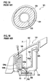
- the headlamp unit 101 comprises a light-emitting diode (LED) 102, a first reflective member 103, a second reflective member 104, a lens 105, a printed board 106 and a cover 107.
- LED light-emitting diode
- the LED 102 is mounted on the printed board 106.
- the LED 102 emits light around an optical axis Z forward therefrom.
- the first reflective member 108 is disposed so as to surround a front side of the LED 102.
- the first reflective member 103 has a main body 103a and a reflection coating 103b formed on a rear surface of the main body 103a.
- the reflection coating 103b is a part of an ellipsoid of revolution formed by rotating an ellipsoid around the optical axis Z, wherein the ellipsoid has a first focus position F1 located near an emitting position of the LED 102 and a second focus position F2 located out of the optical axis Z.
- the second reflective member 104 is disposed so as to be opposed to the first reflective member 103.
- the second reflective member 104 has a main body 104a and a reflection coating 104b formed on a front surface of the main body 104a.
- the reflection coating 104b is a part of a paraboloid of revolution formed by rotating a parabola around a rotation axis parallel to the optical axis Z, wherein the parabola has a focus position located near the second focus position F2 and the rotation axis passes the focus position.
- the lens 105 is annularly disposed to a front side of the second reflective member 104 in order to focus an annularly-shaped beam reflected by the reflection coating 104b and control a distribution of the annularly-shaped beam.
- the cover 107 is made of a transparent member and mounted to a front side of the lens 105 so as to cover it.
- the LED 102 When the LED 102 emits light, the light is reflected by the reflection coating 103b and then focused in the second focus position 72. The light is reflected by the reflection coating 104b and then moves forward as a parallel beam. When the parallel beam enters the lens 105, the parallel beam is focused and distribution-controlled to be emitted in front of the vehicle.
- the headlamp unit 101 lacks compatibility as a headlamp because it has a non-emission region in a center portion of the cover 107 (see FIG. 1A ).
- the headlamp unit 101 also lacks even lighting intensity because it comprises one LED. These lead to poor visibility.
- a lack of lighting intensity causes a plurality of the headlamp assemblies 101 to be installed on the vehicle because the headlamp unit 101 comprises one LED. This leads to a large sized headlamp unit assembly.
- An object of the present invention is to provide a headlamp unit for a vehicle having a structure for maintaining even lighting intensity and realizing a small sized headlamp unit assembly.
- the present invention provides a headlamp unit for a vehicle according to claim 1.
- the headlamp unit can reduce irregular color of the outputting light as a whole because the light distribution pattern comprises light emitted by the plurality of the LEDs. Therefore, since headlamp unit has a structure for maintaining even lighting intensity, this can prevent poor visibility.
- the present invention provides a headlamp unit assembly according to claim 14.
- the headlamp unit can reduce space occupied by one LED in comparison with the conventional headlamp unit. Therefore, in a case where the plurality of the LEDs are installed on a vehicle, space occupied by the headlamp unit assembly can be reduced. As a result, this can realize a small sized headlamp unit assembly.
- FIGS. 2 to 11 An embodiment of the present invention will be described with reference to FIGS. 2 to 11 .
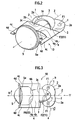
- a headlamp unit for a vehicle 10 comprises LEDs 1, 1, sub-reflectors 2, 2, a main reflector 3, a shade 4, a convex lens 5,screws 6,6 and a mounting plate 9.
- the LED 1 has an emission portion 1a and is disposed near a first focus position F1 of a first reflective surface 2a of the sub-reflector 2 such that the emission portion 1a is opposed to the first reflective surface 2a.
- the sub-reflector 2 projects downward and is made of a thermoplastic resin such as a polycarbonate resin and an acrylic resin.
- One sub-reflector 2 is integrally formed with another sub-reflector 2.
- the sub-reflector 2 has a first reflective surface 2a and an opening 2b.
- the first reflective surface 2a is formed on an inner surface of the sub-reflector 2 by coating or evaporating a film having reflective function on the inner surface.
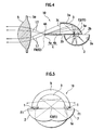
- the first reflective surface 2a is a part of an ellipsoid of revolution formed by rotating an ellipsoid having the first focus position F1 and a second focus position F2.
- the opening 2b is formed on an upper portion of the sub-reflector 2.
- the opening 2b substantially coincides with a horizontal plane including the first focus position F1 and an optical axis Z of the headlamp unit 10.
- the first focus position F1 of one sub-reflector 2 and the first focus position F1 of another sub-reflector 2 are disposed on both sides of the optical axis Z at a hinder part of the headlamp unit 10.
- the second focus position F2 of one sub-reflector 2 and the second focus position F2 of another sub-reflector 2 overlap each other and are disposed on an upper side of the optical axis Z at an anterior part of the headlamp unit 10.
- the main reflector 3 projects upward and is made of a thermoplastic resin such as a polycarbonate resin and an acrylic resin.
- the main reflector 3 has a second reflective surface 3a and openings 3b, 3c.
- the second reflective surface 3a is formed on an inner surface of the main reflector 3 by coating or evaporating a film having reflective function on the inner surface.
- the second reflective surface 3a is a part of an ellipsoid of revolution formed by rotating an ellipsoid having a first focus position f1 located near the second focus position F2 and a second focus position f2 located near a center portion 4A of an end 4a of the shade 4.
- the opening 3b is formed on a bottom portion of the main reflector 3 so as to be substantially parallel to the horizontal plane.
- the opening 3b is located on an upper side of a part of the openings 2b, 2b.
- the opening 3c is substantially semicircular-shaped at an anterior part of the main reflector 3.
- the shade 4 is made of a thermoplastic resin such as a polycarbonate resin and an acrylic resin and has the end 4a, a reflective surface 4b, supporting arms 4c, 4c and lens-engaging portions 4d, 4d.
- the end 4a has the center portion 4A and is formed along a meridional image surface at an anterior part of the shade 4.
- the reflective surface 4b extends from the end 4a toward a hinder part of the shade 4.
- the reflective surface 4b is formed on an upper surface of the shade 4 by coating or evaporating a film having reflective function on the upper surface.
- the supporting arms 4c, 4c extend in parallel with each other forward from both sides of an anterior part of the reflective surface 4b.
- the lens-engaging portions 4d, 4d is formed at portions, which are opposed to each other, of distal ends of the supporting arms 4c, 4c.
- the convex lens 5 is a biconvex and aspherical lens and has a flange portion 5a.
- the flange portion 5a is made of a transparent and thermoplastic resin such as an acrylic resin and mounted on an outer circumference of the convex lens 5.
- the flange portion 5a is engaged to the lens-engaging portions 4d, 4d such that a lens focal point FR of the convex lens 5 substantially coincides with the second focus position f2 (the center portion 4A of the edge 4a).
- the mounting plate 9 is firmly fixed to the LED 1 in the center portion thereof and engaged to a top board (not shown) covering the opening 2b by means of the screws 6, 6.
- Leads 7, 7, 7, 7 are two leads for the LED 1 and two leads for a cooling element.
- Light emitted by the LEDs 1, 1 is reflected on the first reflective surfaces 2a, 2a of the sub-reflectors 2, 2 and then focused near the first focus position f1 (see FIG. 5 ).
- the light is reflected on the second reflective surface 3a of the main reflector 3 and then a part of the light is focused near the second focus position f2.
- One of the light L1 directly enters the convex lens 5 without being reflected by the shade 4 and the other of the light L2 is reflected on the reflective surface 4b of the shade 4 and then enters the convex lens 5.
- the light having entered the convex lens 5 is output forward the headlamp unit 10 to present a desired light distribution pattern.
- the light distribution pattern is suitable a low beam having a cut line that is similar to a cross-section of the reflective surface 4b of the shade 4, wherein the light distribution pattern does not have a non-emission region therewithin.
- light emitted by LED 1 that is located a left side viewed from the hinder part of the headlamp unit 10 (a side of the sub-reflectors 2, 2) is output toward the first reflective surface 2a of the sub-reflector 2 that is located the left side.
- the light is reflected on the first reflective surface 2a and then focused near the first focus position f1 of the second reflective surface 3a.
- the light enters a right side region of the second reflective surface 3a of the main reflector 3. Then, the light is reflected on the second reflective surface 3a and then the part of the light is focused near the second focus position f2 of the second reflective surface 3a.
- One of the light L1 enters a left side region of the convex lens 6 without being reflected by the shade 4 and the other of the light L2 is reflected on the reflective surface 4b of the shade 4 and then enters the left side region of the convex lens 6.
- the light having entered the convex lens 5 is output forward the headlamp unit 10.
- the output light L3 presents a light distribution pattern P1 shown in FIG. 8A .
- light emitted by LED 1 that is located a right side viewed from the hinder part of the headlamp unit 10 (a side of the sub-reflectors 2, 2) is output toward the first reflective surface 2a of the sub-reflector 2 that is located the right side.
- the light is reflected on the first reflective surface 2a and then focused near the first focus position f1 of the second reflective surface 3a.
- the light enters a left side region of the second reflective surface 3a of the main reflector 3. Then, the light is reflected on the second reflective surface 3a and then the part of the light is focused near the second focus position f2 of the second reflective surface 3a.
- One of the light L1 enters a right side region of the convex lens 5 without being reflected by the shade 4 and the other of the light L2 is reflected on the reflective surface 4b of the shade 4 and then enters the right side region of the convex lens 5.
- the light having entered the convex lens 5 is output forward the headlamp unit 10.
- the output light L4 presents a light distribution pattern P2 shown in FIG. 8B .
- the headlamp unit 10 forward outputs an outgoing light presenting a light distribution pattern P0 (see FIG. 8C ) laying the light distribution pattern P2 on the light distribution pattern P1, when the LEDs 1, 1 light at the same time.
- the light distribution pattern P0 is suitable to the low beam having the cut line.
- the headlamp unit 10 utilizes space more effectively in comparison with the conventional headlamp unit because the LEDs 1, 1 and the sub-reflectors 2, 2 are disposed in space under the horizontal plane including the optical axis Z and the main reflector 3 is disposed in space above the horizontal plane.
- the headlamp unit 10 possesses a high-efficiency optical system comprising the first reflective surface 2a and the second reflective surface 3a. That is, although this optical system does not entirely surround the LED 1, it utilizes the beam of the LED 1 of at least 97 % according to a radiation directivity of the LED 1.
- the headlamp unit 10 can reduce irregular color of the outgoing light as a whole because the light distribution pattern P0 comprises the light distribution P1 formed by the light emitted by one LED 1 and the light distribution P2 formed by the light emitted by another LED 1. Therefore, since the headlamp unit 10 has a structure for maintaining even lighting intensity, this can prevent poor visibility.
- the headlamp unit 10 can reduce space occupied by one LED in comparison with the conventional headlamp unit. Therefore, in a case where a plurality of LEDs must be installed on the vehicle, space occupied by a headlamp unit assembly can be reduced. As a result, this can realize a small sized headlamp unit assembly.
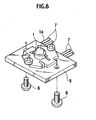
- a headlamp unit assembly A comprises headlamp units 10a, 10b, 10c, 10d, 10e, a lamp housing 13 and a glass 14.
- An upper row of the headlamp unit assembly A is formed with the headlamp units 10a, 10b, 10c.
- a lower row of the headlamp unit assembly A is formed with the headlamp units 10d, 10e.
- the headlamp units 10a, 10b, 10c, 10d, 10e are mounted within the lamp housing 13 having an open front portion. More specifically, the headlamp units 10a, 10b, 10c, 10d, 10e are mounted within the lamp housing 13 via a mounting tool provided with a pivot structure or an aiming screw such that an optical axis of each headlamp unit can be adjusted.
- the glass 14 covers the open front portion of the lamp housing 13.
- FIGS. 10A, 10B, 10C are a horizontal diffusion flat type (a first light distribution pattern), a horizontal diffusion type (a second light distribution pattern) having a cut line of a low beam, a light condensing pattern (a third light distribution pattern) having a cut line of a low beam, respectively.
- one headlamp unit is configured to obtain the third light distribution pattern
- two headlamp units are configured to obtain the first light distribution pattern
- two headlamp units are configured to obtain the second light distribution pattern.
- a flat cut line (the first light distribution pattern) is obtained by causing the reflective surface 4b of the shade 4 to be flat.
- a stepped cut line (the second and third light distribution patterns) is obtained by causing a shape of the cross-section of the reflective surface 4b to be a stepped shape similar to the cut line.
- a diffusion type (the first and second light distribution patterns) is obtained by disposing the LEDs 1, 1 such that a cross angle ⁇ is large wherein the cross angle ⁇ is formed between a line a and a line b passing through center points of the LEDs 1, 1 of the sub-reflector 2, 2 and the second focus positions F2, F2 of the sub-reflector 2, 2 (see FIG. 3 ).
- a light condensing type (the third light distribution pattern) is obtained by disposing the LEDs 1, 1 such that the cross angle ⁇ is small.
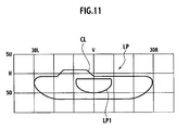
- the headlamp unit assembly A presents a light distribution pattern LP having a high illumination hot zone LP1 and a cut line CL be suitable to a low beam, in front of the vehicle.
- the headlamp unit assembly A becomes to be small and reduces weight thereof because the headlamp units 10a, 10b, 10c, 10d, 10e are made of a resin. It is noted that the number of the sub-reflector 2 having the LED 1 may be equal or more than three.
Landscapes
- Engineering & Computer Science (AREA)
- General Engineering & Computer Science (AREA)
- Physics & Mathematics (AREA)
- Microelectronics & Electronic Packaging (AREA)
- Optics & Photonics (AREA)
- Mathematical Physics (AREA)
- Non-Portable Lighting Devices Or Systems Thereof (AREA)
Claims (14)
- Scheinwerfereinheit (10) für ein Fahrzeug, die umfasst:eine LED (1);eine Vielzahl von Nebenreflektoren (2), die durch die LED (1) emittiertes Licht reflektieren und die eine reflektierende Fläche (2a) sowie eine Öffnung (2b) haben, wobei die reflektierende Fläche (2a) ein Teil eines Rotationsellipsoids ist, der eine erste Fokusposition (F1), die sich an der LED (1) befindet, und eine zweite Fokusposition (F2) hat, die sich an einer Seite einer optischen Achse (Z) der Scheinwerfereinheit (10) befindet;einen Hauptreflektor (3), der so angeordnet ist, dass er den Nebenreflektoren (2) gegenüberliegt und durch die Nebenreflektoren (2) reflektiertes Licht reflektiert; undeine konvexe Linse (5), die durch den Hauptreflektor (3) reflektiertes Licht nach vorn ausgibt, um ein gewünschtes Lichtverteilungsmuster (P0, P1, P2) darzustellen;dadurch gekennzeichnet, dassdie Scheinwerfereinheit (10) eine Vielzahl von LED (1) umfasst, wobei die Vielzahl von Nebenreflektoren (2) jeweils mit der Vielzahl der LED (1) versehen sind,die Öffnung (2b) der Nebenreflektoren (2) sich mit einer horizontalen Ebene deckt, die die optische Achse (Z) einschließt, wobei die Nebenreflektoren (2) dem Hauptreflektor (3) gegenüberliegend von der horizontalen Ebene vorstehen, unddie zweiten Fokuspositionen (F2) der Nebenreflektoren (2) sich an einer anderen Seite der horizontalen Ebene als der Seite befinden, von der die Nebenreflektoren (2) vorstehen.
- Scheinwerfereinheit für ein Fahrzeug (10) nach Anspruch 1, wobei die LED (1) einen der reflektierenden Fläche (2a) des Nebenreflektors (2) gegenüberliegenden emittierenden Abschnitt (1a) hat.
- Scheinwerfereinheit für ein Fahrzeug (10) nach Anspruch 1, wobei die ersten Fokuspositionen (F1) der Nebenreflektoren (2) an einem hinteren Teil der Scheinwerfereinheit (10, 10a, 10b, 10c, 10d, 10e) so angeordnet sind, dass sie einander nicht überlappen, und die zweiten Fokuspositionen (F2) der Nebenreflektoren (2) an einem vorderen Teil der Scheinwerfereinheit (10, 10a, 10b, 10c, 10d, 10e) so angeordnet sind, dass sie einander überlappen.
- Scheinwerfereinheit für ein Fahrzeug (10) nach Anspruch 1, wobei der Nebenreflektor (2) aus einem Thermoplastharz besteht.
- Scheinwerfereinheit für ein Fahrzeug (10) nach Anspruch 1, wobei die reflektierende Fläche (2a) des Nebenreflektors (2) an einer Innenfläche des Nebenreflektors (2) mittels eines Filmes, der mit einer reflektierenden Funktion auf die Innenfläche aufgetragen oder aufgedampft ist, ausgebildet ist.
- Scheinwerfereinheit für ein Fahrzeug (10) nach Anspruch 3, wobei der Hauptreflektor (3) eine reflektierende Fläche (3a) und eine Öffnung (3b) aufweist,
die reflektierende Fläche (3a) ein Teil eines Rotationsellipsoids ist, der eine erste Fokusposition (f1) hat, die sich nahe an der zweiten Fokusposition (F2) des Nebenreflektors (2) befindet, und
die Öffnung (3b) an einem unteren Abschnitt des Hauptreflektors (3) so ausgebildet ist, dass sie im Wesentlichen parallel zu der horizontalen Ebene ist. - Scheinwerfereinheit für ein Fahrzeug (10) nach Anspruch 1, wobei der Hauptreflektor (3) aus einem Thermoplastharz besteht.
- Scheinwerfereinheit für ein Fahrzeug (10) nach Anspruch 1, wobei die reflektierende Fläche (3a) des Hauptreflektors (3) an einer Innenfläche des Hauptreflektors (3) mittels eines Filmes, der mit reflektierender Funktion auf die Innenfläche aufgetragen oder aufgedampft ist, ausgebildet ist.
- Scheinwerfereinheit für ein Fahrzeug (10) nach Anspruch 6, die des Weiteren eine Abschirmung (4) umfasst, die mit der konvexen Linse (5) in Eingriff ist und ein Ende (4a) sowie eine reflektierende Fläche (4b) aufweist, wobei das Ende (4a) entlang einer Meridional-Bildfläche an einem vorderen Teil der Abschirmung (4) ausgebildet ist und sich die reflektierende Fläche (4b) von dem Ende zu einem hinteren Teil der Abschirmung (4) erstreckt.
- Scheinwerfereinheit für ein Fahrzeug (10) nach Anspruch 9, wobei die reflektierende Fläche (3a) des Hauptreflektors (3) eine zweite Fokusposition (f2) hat, die sich nahe an einem Mittelabschnitt (4A) des Endes (4a) befindet.
- Scheinwerfereinheit für ein Fahrzeug (10) nach Anspruch 9, wobei die Abschirmung (4) aus einem Thermoplastharz besteht.
- Scheinwerfereinheit für ein Fahrzeug (10) nach Anspruch 9, wobei die reflektierende Fläche (4b) der Abschirmung (4) an einer oberen Fläche der Abschirmung (4) mittels eines Filmes, der mit reflektierender Funktion auf die obere Fläche aufgetragen oder aufgedampft ist, ausgebildet ist.
- Scheinwerfereinheit für ein Fahrzeug (10) nach Anspruch 10, wobei sich ein Linsen-Fokus (FR) der konvexen Linse (5) im Wesentlichen mit der zweiten Fokusposition (f2) des Hauptreflektors (3) deckt.
- Scheinwerfereinheit-Baugruppe (A), die umfasst:ein Lampengehäuse (13) mit einem offenen Vorderabschnitt;eine Vielzahl von Scheinwerfereinheiten (10a, 10b, 10c, 10d, 10e), die in dem Lampengehäuse (13) so angebracht sind, dass eine optische Achse (Z) jeder Scheinwerfereinheit (10a, 10b, 10c, 10d, 10e) eingestellt werden kann; undein Glas (14), das den offenen Vorderabschnitt abdeckt,dadurch gekennzeichnet, dassjede Scheinwerfereinheit (10a, 10b, 10c, 10d, 10e) aus der Scheinwerfereinheit (10) nach einem der vorangehenden Ansprüche besteht.
Applications Claiming Priority (2)
| Application Number | Priority Date | Filing Date | Title |
|---|---|---|---|
| JP2004148287 | 2004-05-18 | ||
| JP2004148287A JP2005332640A (ja) | 2004-05-18 | 2004-05-18 | 車両用前照灯ユニット |
Publications (3)
| Publication Number | Publication Date |
|---|---|
| EP1598593A2 EP1598593A2 (de) | 2005-11-23 |
| EP1598593A3 EP1598593A3 (de) | 2009-03-25 |
| EP1598593B1 true EP1598593B1 (de) | 2011-04-20 |
Family
ID=34936650
Family Applications (1)
| Application Number | Title | Priority Date | Filing Date |
|---|---|---|---|
| EP05010778A Expired - Lifetime EP1598593B1 (de) | 2004-05-18 | 2005-05-18 | Scheinwerfer für ein Fahrzeug |
Country Status (4)
| Country | Link |
|---|---|
| US (1) | US7207703B2 (de) |
| EP (1) | EP1598593B1 (de) |
| JP (1) | JP2005332640A (de) |
| DE (1) | DE602005027517D1 (de) |
Families Citing this family (21)
| Publication number | Priority date | Publication date | Assignee | Title |
|---|---|---|---|---|
| CN101132950B (zh) * | 2005-03-04 | 2012-07-11 | 奥斯兰姆施尔凡尼亚公司 | 发光二极管前照灯系统 |
| US20070047235A1 (en) * | 2005-08-24 | 2007-03-01 | Cooper Technologies Company | Method and apparatus for providing light |
| US20070047234A1 (en) * | 2005-08-24 | 2007-03-01 | Cooper Technologies Company | Method and apparatus for providing light |
| US7410282B2 (en) * | 2005-10-25 | 2008-08-12 | Visteon Global Technologies, Inc. | Bi-functional headlight module |
| EP1798467B1 (de) * | 2005-12-14 | 2008-02-13 | T.Y.C. Brother Industrial Co., Ltd. | Projektions-Beleuchtungseinrichtung |
| FR2896852B1 (fr) | 2006-01-27 | 2008-02-29 | Valeo Vision Sa | Projecteur a led pour vehicule automobile. |
| JP4535453B2 (ja) * | 2006-03-06 | 2010-09-01 | 株式会社小糸製作所 | 光源モジュール及び車輌用灯具 |
| DE102007016294B4 (de) * | 2006-04-11 | 2009-04-02 | Koito Manufacturing Co., Ltd. | Fahrzeugleuchte |
| DE102006041942A1 (de) * | 2006-09-07 | 2008-03-27 | Hella Kgaa Hueck & Co. | Projektionsscheinwerfer für Fahrzeuge |
| JP4783257B2 (ja) * | 2006-10-19 | 2011-09-28 | スタンレー電気株式会社 | 半導体発光素子を光源とする車両前照灯用の投影レンズ |
| US20100246203A1 (en) * | 2009-03-27 | 2010-09-30 | North American Lighting, Inc. | System and method for exterior lighting of vehicles |
| KR101619832B1 (ko) * | 2009-11-30 | 2016-05-13 | 삼성전자주식회사 | 발광다이오드 패키지, 이를 구비한 발광다이오드 패키지 모듈과 그 제조 방법, 및 이를 구비한 헤드 램프 모듈과 그 제어 방법 |
| FR2996281A1 (fr) | 2012-10-01 | 2014-04-04 | Valeo Vision | Dispositif d'actionnement d'un element optique d'un dispositif d'eclairage et/ou de signalisation |
| JP6180772B2 (ja) * | 2013-04-01 | 2017-08-16 | 株式会社小糸製作所 | 車両用灯具 |
| JP6111805B2 (ja) * | 2013-04-04 | 2017-04-12 | 市光工業株式会社 | 車両用灯具 |
| FR3010770B1 (fr) | 2013-07-24 | 2018-02-02 | Valeo Vision Belgique | Module d'eclairage et/ou de signalisation notamment pour vehicule, avec une partie centrale n'emettant pas de lumiere |
| JP2015056228A (ja) * | 2013-09-10 | 2015-03-23 | 株式会社小糸製作所 | プリント基板および車両用灯具 |
| US9651211B2 (en) | 2014-10-16 | 2017-05-16 | Valeo North America, Inc. | Multi-function optical system with shared exit optic |
| JP6517556B2 (ja) * | 2015-03-24 | 2019-05-22 | スタンレー電気株式会社 | 車両用灯具 |
| TWI642568B (zh) * | 2016-09-07 | 2018-12-01 | 世正光電股份有限公司 | 照明結構及其配光方法 |
| CN113007643B (zh) * | 2021-03-22 | 2022-06-24 | 江西亚中电子科技股份有限公司 | 一种led透镜可调多功能灯架 |
Family Cites Families (4)
| Publication number | Priority date | Publication date | Assignee | Title |
|---|---|---|---|---|
| US6796696B2 (en) * | 2000-12-05 | 2004-09-28 | Stanley Electric Co., Ltd. | Vehicle light with movable reflector portion and shutter portion for selectively switching an illuminated area of light incident on a predetermined portion of the vehicle light during driving |
| FR2826098B1 (fr) * | 2001-06-14 | 2003-12-26 | Valeo Vision | Dispositif d'eclairage ou de signalisation, notamment pour vehicule, comportant plusieurs sources lumineuses |
| JP4123338B2 (ja) | 2002-02-01 | 2008-07-23 | スタンレー電気株式会社 | 灯具 |
| JP4083593B2 (ja) * | 2003-02-13 | 2008-04-30 | 株式会社小糸製作所 | 車両用前照灯 |
-
2004
- 2004-05-18 JP JP2004148287A patent/JP2005332640A/ja active Pending
-
2005
- 2005-05-18 DE DE602005027517T patent/DE602005027517D1/de not_active Expired - Lifetime
- 2005-05-18 EP EP05010778A patent/EP1598593B1/de not_active Expired - Lifetime
- 2005-05-18 US US11/131,789 patent/US7207703B2/en not_active Expired - Fee Related
Also Published As
| Publication number | Publication date |
|---|---|
| US20050259431A1 (en) | 2005-11-24 |
| EP1598593A3 (de) | 2009-03-25 |
| EP1598593A2 (de) | 2005-11-23 |
| US7207703B2 (en) | 2007-04-24 |
| JP2005332640A (ja) | 2005-12-02 |
| DE602005027517D1 (de) | 2011-06-01 |
Similar Documents
| Publication | Publication Date | Title |
|---|---|---|
| EP1598593B1 (de) | Scheinwerfer für ein Fahrzeug | |
| EP2019257B1 (de) | Fahrzeugbeleuchtungsanordnung und Lichtführungslinse zur Verwendung in einer Fahrzeugbeleuchtungsanordnung | |
| US6805476B2 (en) | Led-type vehicular lamp having uniform brightness | |
| US7134775B2 (en) | Vehicular headlamp and light-emitting module therefor | |
| JP4047266B2 (ja) | 灯具 | |
| JP4270093B2 (ja) | プロジェクタ型車両用前照灯ユニット | |
| JP4289268B2 (ja) | 車両用前照灯ユニット | |
| US7736039B2 (en) | Vehicle lamp | |
| EP2487407B1 (de) | Fahrzeugbeleuchtungsvorrichtung | |
| US20050162857A1 (en) | Lamp unit for vehicle and illumination lamp for vehicle | |
| US7341366B2 (en) | Projector type vehicle headlamp unit | |
| CN110425493A (zh) | 灯具单元 | |
| US10253940B1 (en) | Vehicle light assembly | |
| JP2012256457A (ja) | 車両用前照灯 | |
| EP2988059A1 (de) | Fahrzeuglicht | |
| EP3540295B1 (de) | Fahrzeug-scheinwerfer-anordnung | |
| WO2001002771A1 (en) | Luminaire and signaling lamp | |
| JP2005302328A (ja) | プロジェクタ型車両用灯具 | |
| KR101959804B1 (ko) | 차량용 램프 | |
| JP2005209602A (ja) | プロジェクタ型車両用灯具 | |
| EP2587118B1 (de) | LED-Deckenlampe | |
| JP2017212036A (ja) | 車両用灯具 | |
| WO2024048390A1 (ja) | ランプユニット、車両用灯具 | |
| KR101691847B1 (ko) | 차량용 헤드램프 | |
| WO2026063190A1 (ja) | エンブレムランプ |
Legal Events
| Date | Code | Title | Description |
|---|---|---|---|
| PUAI | Public reference made under article 153(3) epc to a published international application that has entered the european phase |
Free format text: ORIGINAL CODE: 0009012 |
|
| AK | Designated contracting states |
Kind code of ref document: A2 Designated state(s): AT BE BG CH CY CZ DE DK EE ES FI FR GB GR HU IE IS IT LI LT LU MC NL PL PT RO SE SI SK TR |
|
| AX | Request for extension of the european patent |
Extension state: AL BA HR LV MK YU |
|
| PUAL | Search report despatched |
Free format text: ORIGINAL CODE: 0009013 |
|
| AK | Designated contracting states |
Kind code of ref document: A3 Designated state(s): AT BE BG CH CY CZ DE DK EE ES FI FR GB GR HU IE IS IT LI LT LU MC NL PL PT RO SE SI SK TR |
|
| AX | Request for extension of the european patent |
Extension state: AL BA HR LV MK YU |
|
| 17P | Request for examination filed |
Effective date: 20090420 |
|
| 17Q | First examination report despatched |
Effective date: 20090902 |
|
| AKX | Designation fees paid |
Designated state(s): DE FR GB |
|
| GRAP | Despatch of communication of intention to grant a patent |
Free format text: ORIGINAL CODE: EPIDOSNIGR1 |
|
| GRAS | Grant fee paid |
Free format text: ORIGINAL CODE: EPIDOSNIGR3 |
|
| GRAA | (expected) grant |
Free format text: ORIGINAL CODE: 0009210 |
|
| AK | Designated contracting states |
Kind code of ref document: B1 Designated state(s): DE FR GB |
|
| REG | Reference to a national code |
Ref country code: GB Ref legal event code: FG4D |
|
| REF | Corresponds to: |
Ref document number: 602005027517 Country of ref document: DE Date of ref document: 20110601 Kind code of ref document: P |
|
| REG | Reference to a national code |
Ref country code: DE Ref legal event code: R096 Ref document number: 602005027517 Country of ref document: DE Effective date: 20110601 |
|
| PLBE | No opposition filed within time limit |
Free format text: ORIGINAL CODE: 0009261 |
|
| STAA | Information on the status of an ep patent application or granted ep patent |
Free format text: STATUS: NO OPPOSITION FILED WITHIN TIME LIMIT |
|
| 26N | No opposition filed |
Effective date: 20120123 |
|
| REG | Reference to a national code |
Ref country code: DE Ref legal event code: R097 Ref document number: 602005027517 Country of ref document: DE Effective date: 20120123 |
|
| PGFP | Annual fee paid to national office [announced via postgrant information from national office to epo] |
Ref country code: DE Payment date: 20120516 Year of fee payment: 8 |
|
| PGFP | Annual fee paid to national office [announced via postgrant information from national office to epo] |
Ref country code: FR Payment date: 20120608 Year of fee payment: 8 Ref country code: GB Payment date: 20120516 Year of fee payment: 8 |
|
| GBPC | Gb: european patent ceased through non-payment of renewal fee |
Effective date: 20130518 |
|
| PG25 | Lapsed in a contracting state [announced via postgrant information from national office to epo] |
Ref country code: DE Free format text: LAPSE BECAUSE OF NON-PAYMENT OF DUE FEES Effective date: 20131203 |
|
| REG | Reference to a national code |
Ref country code: DE Ref legal event code: R119 Ref document number: 602005027517 Country of ref document: DE Effective date: 20131203 |
|
| REG | Reference to a national code |
Ref country code: FR Ref legal event code: ST Effective date: 20140131 |
|
| PG25 | Lapsed in a contracting state [announced via postgrant information from national office to epo] |
Ref country code: GB Free format text: LAPSE BECAUSE OF NON-PAYMENT OF DUE FEES Effective date: 20130518 |
|
| PG25 | Lapsed in a contracting state [announced via postgrant information from national office to epo] |
Ref country code: FR Free format text: LAPSE BECAUSE OF NON-PAYMENT OF DUE FEES Effective date: 20130531 |