US7134775B2 - Vehicular headlamp and light-emitting module therefor - Google Patents

Vehicular headlamp and light-emitting module therefor Download PDF

Info

Publication number
US7134775B2
US7134775B2 US10/769,990 US76999004A US7134775B2 US 7134775 B2 US7134775 B2 US 7134775B2 US 76999004 A US76999004 A US 76999004A US 7134775 B2 US7134775 B2 US 7134775B2
Authority
US
United States
Prior art keywords
light
emitting element
semiconductor light
emitting
vehicular headlamp
Prior art date
Legal status (The legal status is an assumption and is not a legal conclusion. Google has not performed a legal analysis and makes no representation as to the accuracy of the status listed.)
Active, expires
Application number
US10/769,990
Other versions
US20040240219A1 (en
Inventor
Kazutami Oishi
Kiyoshi Sazuka
Current Assignee (The listed assignees may be inaccurate. Google has not performed a legal analysis and makes no representation or warranty as to the accuracy of the list.)
Koito Manufacturing Co Ltd
Original Assignee
Koito Manufacturing Co Ltd
Priority date (The priority date is an assumption and is not a legal conclusion. Google has not performed a legal analysis and makes no representation as to the accuracy of the date listed.)
Filing date
Publication date
Application filed by Koito Manufacturing Co Ltd filed Critical Koito Manufacturing Co Ltd
Assigned to KOITO MANUFACTURING CO., LTD reassignment KOITO MANUFACTURING CO., LTD ASSIGNMENT OF ASSIGNORS INTEREST (SEE DOCUMENT FOR DETAILS). Assignors: OISHI, KAZUTAMI, SAZUKA, KIYOSHI
Publication of US20040240219A1 publication Critical patent/US20040240219A1/en
Application granted granted Critical
Publication of US7134775B2 publication Critical patent/US7134775B2/en
Active legal-status Critical Current
Adjusted expiration legal-status Critical

Links

Images

Classifications

    • FMECHANICAL ENGINEERING; LIGHTING; HEATING; WEAPONS; BLASTING
    • F21LIGHTING
    • F21SNON-PORTABLE LIGHTING DEVICES; SYSTEMS THEREOF; VEHICLE LIGHTING DEVICES SPECIALLY ADAPTED FOR VEHICLE EXTERIORS
    • F21S41/00Illuminating devices specially adapted for vehicle exteriors, e.g. headlamps
    • F21S41/10Illuminating devices specially adapted for vehicle exteriors, e.g. headlamps characterised by the light source
    • F21S41/14Illuminating devices specially adapted for vehicle exteriors, e.g. headlamps characterised by the light source characterised by the type of light source
    • F21S41/18Combination of light sources of different types or shapes
    • FMECHANICAL ENGINEERING; LIGHTING; HEATING; WEAPONS; BLASTING
    • F21LIGHTING
    • F21SNON-PORTABLE LIGHTING DEVICES; SYSTEMS THEREOF; VEHICLE LIGHTING DEVICES SPECIALLY ADAPTED FOR VEHICLE EXTERIORS
    • F21S41/00Illuminating devices specially adapted for vehicle exteriors, e.g. headlamps
    • F21S41/10Illuminating devices specially adapted for vehicle exteriors, e.g. headlamps characterised by the light source
    • F21S41/12Illuminating devices specially adapted for vehicle exteriors, e.g. headlamps characterised by the light source characterised by the type of emitted light
    • F21S41/13Ultraviolet light; Infrared light
    • FMECHANICAL ENGINEERING; LIGHTING; HEATING; WEAPONS; BLASTING
    • F21LIGHTING
    • F21SNON-PORTABLE LIGHTING DEVICES; SYSTEMS THEREOF; VEHICLE LIGHTING DEVICES SPECIALLY ADAPTED FOR VEHICLE EXTERIORS
    • F21S41/00Illuminating devices specially adapted for vehicle exteriors, e.g. headlamps
    • F21S41/10Illuminating devices specially adapted for vehicle exteriors, e.g. headlamps characterised by the light source
    • F21S41/14Illuminating devices specially adapted for vehicle exteriors, e.g. headlamps characterised by the light source characterised by the type of light source
    • F21S41/141Light emitting diodes [LED]
    • F21S41/147Light emitting diodes [LED] the main emission direction of the LED being angled to the optical axis of the illuminating device
    • F21S41/148Light emitting diodes [LED] the main emission direction of the LED being angled to the optical axis of the illuminating device the main emission direction of the LED being perpendicular to the optical axis
    • FMECHANICAL ENGINEERING; LIGHTING; HEATING; WEAPONS; BLASTING
    • F21LIGHTING
    • F21SNON-PORTABLE LIGHTING DEVICES; SYSTEMS THEREOF; VEHICLE LIGHTING DEVICES SPECIALLY ADAPTED FOR VEHICLE EXTERIORS
    • F21S41/00Illuminating devices specially adapted for vehicle exteriors, e.g. headlamps
    • F21S41/10Illuminating devices specially adapted for vehicle exteriors, e.g. headlamps characterised by the light source
    • F21S41/14Illuminating devices specially adapted for vehicle exteriors, e.g. headlamps characterised by the light source characterised by the type of light source
    • F21S41/141Light emitting diodes [LED]
    • F21S41/151Light emitting diodes [LED] arranged in one or more lines
    • FMECHANICAL ENGINEERING; LIGHTING; HEATING; WEAPONS; BLASTING
    • F21LIGHTING
    • F21SNON-PORTABLE LIGHTING DEVICES; SYSTEMS THEREOF; VEHICLE LIGHTING DEVICES SPECIALLY ADAPTED FOR VEHICLE EXTERIORS
    • F21S41/00Illuminating devices specially adapted for vehicle exteriors, e.g. headlamps
    • F21S41/10Illuminating devices specially adapted for vehicle exteriors, e.g. headlamps characterised by the light source
    • F21S41/14Illuminating devices specially adapted for vehicle exteriors, e.g. headlamps characterised by the light source characterised by the type of light source
    • F21S41/141Light emitting diodes [LED]
    • F21S41/155Surface emitters, e.g. organic light emitting diodes [OLED]
    • FMECHANICAL ENGINEERING; LIGHTING; HEATING; WEAPONS; BLASTING
    • F21LIGHTING
    • F21YINDEXING SCHEME ASSOCIATED WITH SUBCLASSES F21K, F21L, F21S and F21V, RELATING TO THE FORM OR THE KIND OF THE LIGHT SOURCES OR OF THE COLOUR OF THE LIGHT EMITTED
    • F21Y2115/00Light-generating elements of semiconductor light sources
    • F21Y2115/10Light-emitting diodes [LED]
    • HELECTRICITY
    • H01ELECTRIC ELEMENTS
    • H01LSEMICONDUCTOR DEVICES NOT COVERED BY CLASS H10
    • H01L25/00Assemblies consisting of a plurality of individual semiconductor or other solid state devices ; Multistep manufacturing processes thereof
    • H01L25/03Assemblies consisting of a plurality of individual semiconductor or other solid state devices ; Multistep manufacturing processes thereof all the devices being of a type provided for in the same subgroup of groups H01L27/00 - H01L33/00, or in a single subclass of H10K, H10N, e.g. assemblies of rectifier diodes
    • H01L25/04Assemblies consisting of a plurality of individual semiconductor or other solid state devices ; Multistep manufacturing processes thereof all the devices being of a type provided for in the same subgroup of groups H01L27/00 - H01L33/00, or in a single subclass of H10K, H10N, e.g. assemblies of rectifier diodes the devices not having separate containers
    • H01L25/075Assemblies consisting of a plurality of individual semiconductor or other solid state devices ; Multistep manufacturing processes thereof all the devices being of a type provided for in the same subgroup of groups H01L27/00 - H01L33/00, or in a single subclass of H10K, H10N, e.g. assemblies of rectifier diodes the devices not having separate containers the devices being of a type provided for in group H01L33/00
    • H01L25/0753Assemblies consisting of a plurality of individual semiconductor or other solid state devices ; Multistep manufacturing processes thereof all the devices being of a type provided for in the same subgroup of groups H01L27/00 - H01L33/00, or in a single subclass of H10K, H10N, e.g. assemblies of rectifier diodes the devices not having separate containers the devices being of a type provided for in group H01L33/00 the devices being arranged next to each other
    • HELECTRICITY
    • H01ELECTRIC ELEMENTS
    • H01LSEMICONDUCTOR DEVICES NOT COVERED BY CLASS H10
    • H01L2924/00Indexing scheme for arrangements or methods for connecting or disconnecting semiconductor or solid-state bodies as covered by H01L24/00
    • H01L2924/0001Technical content checked by a classifier
    • H01L2924/0002Not covered by any one of groups H01L24/00, H01L24/00 and H01L2224/00

Definitions

  • the present invention relates to a vehicular headlamp and a light-emitting module therefore.
  • a vehicular headlamp employed in a vehicle includes a first semiconductor light-emitting element for emitting visible light, a reflector having an optical center in the vicinity of the semiconductor light-emitting element and forming at least a part of a light distribution pattern of the vehicular headlamp by reflecting visible light, and a second semiconductor light-emitting element for emitting infrared light, the second element being positioned differently from the first element, the reflector also reflecting infrared light from the first element.
  • the inventive vehicular headlamp radiates visible light forwardly of the vehicle.
  • the vehicular headlamp may include a sealing member made of a material that transmits visible light and infrared light, and which integrally houses and seals the first and second semiconductor light-emitting elements.
  • the reflector reflects visible light and infrared light generally in the forward direction, with the infrared light reflected at a greater elevational angle than that of the visible light.
  • the reflector may be a mirrored surface which extends forwardly from the rear of the first semiconductor light-emitting element so as to cover the first element, and which reflects visible light forwardly of the vehicle.
  • the second semiconductor light-emitting element may be disposed between the first semiconductor light-emitting element and a rear end of the reflector.
  • the second semiconductor light-emitting element may be disposed farther from the optical center of the reflector than the first semiconductor light-emitting element.
  • a light-emitting module includes a first semiconductor light-emitting element for emitting visible light to be used in a vehicular headlamp, a second semiconductor light-emitting element for emitting infrared light, and a sealing member which integrally houses and seals the first and second semiconductor light-emitting elements, and which is made of a material that transmits visible light and infrared light.
  • FIG. 1 is a drawing showing an example of a configuration of a vehicular lamp constructed according to a preferred embodiment of the present invention.
  • FIGS. 2 and 2A are drawings showing examples of a light source unit.
  • FIG. 3 is a drawing showing a vertical sectional view of a light source taken along a line III—III.
  • FIG. 4 is a drawing showing a top view of the light source also showing the line III—III.
  • FIG. 5 is a drawing showing an example of a light distribution pattern formed by the light source unit.
  • FIG. 6 is a drawing showing a front view of the light source unit.
  • FIG. 7 is a vertical sectional view of the light source unit taken along a line VII—VII.
  • FIG. 8 is a horizontal sectional view of the light source unit taken along a line VIII—VIII.
  • FIG. 9 is a drawing showing an example of a visible light pattern.
  • FIG. 10 is a drawing showing an example of an infrared light pattern.
  • FIG. 11 is a drawing showing an example of a visible light pattern.
  • FIG. 12 is a drawing showing an example of an infrared light pattern.
  • FIG. 1 shows an example of a vehicular lamp 400 constructed according to a preferred embodiment of the present invention.
  • One goal of the vehicular lamp 400 is to radiate visible light and infrared light while providing a lamp having a low manufacturing cost.
  • the vehicular lamp 400 which radiates a low beam, includes a plurality of light source units 100 housed in a substantially horizontal row in a lamp chamber formed by a substantially translucent and transparent cover 402 and a lamp body 404 .
  • These light source units 100 have the same or similar configurations and are housed in the lamp chamber such that optical axes thereof are oriented downwardly by 0.3° to 0.6° with respect to the longitudinal direction when the vehicular lamp 400 is installed in the vehicle.
  • the vehicular lamp 400 radiates light from these light source units 100 forwardly of the vehicle and forms a predetermined light distribution pattern.
  • Each of the light source units 100 may have different light distribution characteristics which contribute to that light distribution pattern.
  • the vehicular lamp 400 may include a single light source unit 100 which produces the desired light distribution pattern.
  • FIG. 2 shows an example of the light source unit 100 , which is a parabolic light source unit which radiates light forwardly using a parabolic reflecting surface.
  • the unit 100 includes a front cover 106 , a bottom surface portion 108 , a light source 102 and a reflector 104 .
  • the light source unit 100 radiates visible light and infrared light forwardly.
  • the visible light is white light to be used for ordinary illumination for the vehicular headlamp.
  • the bottom surface portion 108 which is substantially flat, is provided on a bottom surface of the light source unit 100 .
  • the light source 102 is provided on an upper surface of the bottom portion 108 .
  • the front cover 106 which is substantially transparent, covers the front face of the light source unit 100 , transmits light reflected by the reflector 104 forwardly of the light source unit 100 .
  • the light source 102 is a light-emitting diode module which has a first, visible light LED 202 and a second, infrared light LED 204 which emit visible light and infrared light respectively, and a sealing member 214 which houses and seals the two LEDs 202 , 204 .
  • the infrared light LED 204 is disposed between the visible light LED 202 and a rear end of the reflector 104 .
  • the reflector 104 is a mirrored surface which extends above and forwardly from the rear of the light source 102 to cover the light source 102 .
  • the reflector forms at least a part of the light distribution pattern of the light source unit 100 by reflecting visible light emitted by the visible light LED 202 in a forward direction.
  • the reflector 104 also reflects infrared light emitted by the infrared light LED 204 in the forward direction.
  • the infrared light LED 204 is positioned more closely to the rear end of the reflector 104 than the visible light LED 202 . Therefore, the portion of the reflector 104 that passes over the top of the light source 102 reflects infrared light to a higher elevation than it reflects the visible light.
  • the light source unit 100 functions as an infrared projector which projects infrared light.
  • the light source unit 100 functions as an infrared projector which projects infrared light.
  • a highly advanced vehicular headlamp capable of radiating both visible light and infrared light at low cost.
  • a vehicle can utilize the infrared light for night-vision using an infrared light camera, or for detecting obstacles in front of the vehicle, among other uses.
  • the reflector 104 has its optical center, which is a focal point or an optical reference point or the like, in the vicinity of the visible light LED 202 . In this case, the reflector 104 reflects visible light emitted by the visible light LED 202 quite accurately.
  • the reflecting surface of the reflector 104 is parabolic so as to reflect incident light from the focal point as a substantially parallel light flux substantially in the optical axis direction.
  • the infrared light LED 204 is farther from the focal point of the reflector 104 than is the visible light LED 202 . Therefore, the reflector 104 radiates infrared light across a wider area than it radiates visible light.
  • the light source unit 100 may be a projector type, which radiates, for example, light reflected and condensed close to the optical axis, forwardly through a lens.
  • the reflector 104 may be a composite ellipsoid mirrored surface, for example.
  • the reflecting surface of the reflector 104 may be formed with a generally ellipsoid spherical shape having one focal point and another focal point, for example, in the vicinity of the visible light LED 202 and in the vicinity of a front end of the bottom surface portion 108 . With this structure, the reflector 104 will substantially condense light emitted by the light source 102 in the vicinity of the other focal point.
  • the light source unit 100 also may include, in place of the front cover 106 , a lens which is disposed farther in front of a front end of the bottom surface portion 108 , and which has a lens for which the other focal point serves as a focal point.
  • the front cover 106 which serves as a lens may form a cut-off line of the light distribution pattern based on the shape of the front edge.
  • the light source unit 100 is capable of radiating infrared light. It should be noted that at least a part of a top surface of the bottom surface portion 108 also may reflect light.
  • FIGS. 3 and 4 show the configuration of the light source 102 in detail.
  • FIG. 3 is a vertical sectional view of the light source 102 taken along the line III—III in FIG. 4 .
  • FIG. 4 is a top view of the light source 102 .
  • the light source 102 is an example of a light-emitting module that includes the visible light LED 202 , a fluorescent body 210 , the infrared light LED 204 , a visible light reflector 208 , an infrared light reflector 206 , a base board 212 , and the sealing member 214 .
  • the visible light LED 202 may be, for example, a semiconductor light-emitting diode that emits blue light or ultraviolet light.
  • the fluorescent body 210 which is disposed between the visible light LED 202 and the sealing member 214 , emits visible light to be used by the light source unit 100 (see FIG. 2 ) in accordance with the light emitted by the visible light LED 202 .
  • the fluorescent body 210 is disposed, for example, on the visible light LED 202 so as to generally cover the visible light LED 202 .
  • the fluorescent body 210 may cover a part of the top surface of the visible light LED 202 .
  • the fluorescent body 210 may emit amber light, which is a complementary color to blue light.
  • the light source 102 radiates white light based on blue light and yellow light emitted by the visible light LED 202 and the fluorescent body 210 , respectively.
  • the fluorescent body 210 may also emit white light in response to the ultraviolet light emitted by the visible light LED 202 .
  • the fluorescent body 210 may have light transmission characteristics which are complementary to the characteristics of the light that the visible light LED 202 emits, so that what emerges from the fluorescent body 210 is substantially white light.
  • the infrared light LED 204 may be, for example, a semiconductor light-emitting element which emits infrared light as well as red light.
  • the infrared light LED 204 which is disposed at a different position from that of the visible light LED 202 , emits red light to be reflected by the reflector 104 (see FIG. 2 ).
  • the visible light LED 202 is mounted on the bottom surface of the visible light reflector 208 .
  • the visible light reflector 208 extends upwardly and outwardly from the perimeter of its bottom surface.
  • An inner wall surface formed by the reflecting surface surrounds the visible light LED 202 so as to reflect upwardly visible light, whereby light from the LED 202 stimulates the fluorescent body 210 to emit visible light. Accordingly, it is possible to utilize efficiently emitted visible light.
  • the visible light reflector 208 isolates the fluorescent body 210 disposed on the visible light LED from the infrared light LED 204 . In this manner, it is possible to prevent infrared light emitted by the infrared light LED 204 from being absorbed by the fluorescent body 210 .
  • the infrared light reflector 206 which has a function that is the same as or similar to that of the visible light reflector 208 , reflects infrared light emitted by the infrared light LED 204 upwardly. Accordingly, it is possible to utilize efficiently the infrared light that has been emitted.
  • the base board 212 fixes the visible light LED 202 and the infrared light LED 204 at predetermined positions in that the visible light reflector 208 and the infrared light reflector 206 are secured to the upper surface of the base board 212 .
  • the sealing member 214 which is formed of a material that transmits visible light and infrared light, integrally houses and seals the visible light LED 202 and the infrared light LED 204 .
  • the visible light LED 202 and the infrared light LED 204 were installed on the light source unit 100 as individual LED modules, the necessary mounting space would increase and the configuration required for installation would be more complicated. However, in the embodiment described, since the visible light LED 202 and the infrared light LED 204 are housed integrally and are sealed by the sealing member 214 , it is possible to install them easily in a limited space with a simple configuration.
  • a vehicular headlamp requires a highly accurate light distribution pattern, it is necessary to specify the positions of the visible light LED 202 and the infrared light LED 204 very accurately. Therefore, there are some cases when it is necessary to make the distance between the infrared light LED 204 and the visible light LED 202 smaller than the sizes of the infrared light LED 204 or the visible light LED 202 . Also, in such a case, it is possible to specify the positions of the infrared light LED 204 and the visible light LED 202 very accurately, so that the light source unit 100 (see FIG. 2 ) can form an appropriate light distribution pattern.
  • a single visible light reflector 208 may hold both the visible light LED 202 and the infrared light LED 204 . As a result, it is possible to provide the visible light LED 202 and the infrared light LED 204 in a more limited space.
  • the light source 102 may include three types of semiconductor light-emitting elements 203 a , 203 b and 203 c , which emit red, green, and blue light, respectively (see FIG. 2 a ). In this case, since there would be no fluorescent body 210 which can deteriorate over time, the light source 102 can last longer.
  • FIG. 5 is a rear cross-sectional view showing the light source unit 100 and an example of a light distribution pattern 300 that the light source unit 100 forms.
  • the light distribution pattern 300 is a low-beam light distribution pattern which is formed on a virtual vertical screen positioned 25 m ahead of the light source unit 100 .
  • the light source unit 100 forms a visible light pattern 304 formed by white light based on light emitted by the visible light LED 202 , and an infrared light pattern 302 based on infrared light emitted by the infrared light LED 204 .
  • the light source unit 100 radiates visible light substantially forwardly of the vehicle so as to form the visible light pattern 304 , which has an oblique cut-off line 306 and a horizontal cut-off line 308 that define a contrast boundary in the light distribution pattern. Further, as explained with reference to FIG. 2 , in one embodiment, the reflector 104 reflects infrared light to a higher elevation than the visible light. Accordingly, the light source unit 100 forms the infrared light pattern 302 with a center at a higher elevation than that of the visible light pattern 304 .
  • a conventional infrared light projector sometimes emits visible red light as well as red light in the infrared range.
  • emission of red light is not desirable from a safety viewpoint, and is subject to regulatory control for vehicular headlamps.
  • the red light accompanying emission of infrared light is substantially diluted by white light in regions where the infrared light pattern 302 and the visible light pattern 304 overlap each other.
  • the infrared light LED 204 and the visible light LED 202 are adjacent to each other and are disposed in the same light source unit 100 . Therefore, even in areas outside of the overlapping regions in the infrared light pattern 302 , it is possible to make the red light accompanying emission of infrared light appear dim.
  • the infrared light LED 204 is farther from the focal point of the reflector 104 than is the visible light LED 202 . Therefore, the infrared light pattern 302 spreads across a wider area than does the visible light pattern 304 .
  • the vehicular lamp 400 may form the light distribution pattern 300 based on, for example, light emitted by the plurality of light source units 100 having different light distribution characteristics.
  • Each of the light source units 100 may radiate light to a part of the light distribution pattern 302 .
  • FIGS. 6 , 7 , and 8 show another example of the light source unit 100 .
  • FIG. 6 is a front view of the light source unit 100
  • FIG. 7 is a vertical sectional view of the light source unit 100 along line VII—VII in FIGS. 6 and 8
  • FIG. 8 is a horizontal sectional view of the light source unit 100 along line VIII—VIII in FIGS. 6 and 7 .
  • the light source unit 100 according to this example includes a light source retention portion 506 , a plurality of light sources 102 a , 102 b and a plurality of reflectors 104 a , 104 b.
  • the light source retention portion 506 is a substantially flat body, with a front side and a back side which are substantially parallel to and substantially perpendicular to an optical axis of the light source unit 100 , and on which the plurality of light sources 102 a , 102 b are respectively retained.
  • the light source retention portion 506 retains the light source 102 a and the light source 102 b so that they face in the lateral direction of the vehicle, and causes light emitted by the plurality of light sources 102 a , 102 b to be incident on the plurality of reflectors 104 a , 104 b , respectively.
  • the light source 102 a includes a visible light LED 202 a , an infrared light LED 204 a , and a sealing member 214 a .
  • the visible light LED 202 a , the infrared light LED 204 a , and the sealing member 214 a have the same or similar functions as the visible light LED 202 , the infrared light LED 204 , and the sealing member 214 that were explained with reference to FIGS. 3 and 4 .
  • the visible light LED 202 a and the infrared light LED 204 a are generally square shaped, with approximately 1 mm sides. As shown in FIG. 7 , the infrared light LED 204 a is approximately 0.2 mm to the rear of and below the visible light LED 202 a in the longitudinal direction and the vertical direction of the vehicle, respectively. Moreover, as shown in FIG. 8 , the infrared light LED 204 a is approximately 0.2 mm closer to the reflector 104 a than the visible light LED 202 a in the lateral direction.
  • the light source 102 b includes a visible light LED 202 b , an infrared light LED 204 b , and a sealing member 214 b .
  • the infrared light LED 204 b is approximately 0.2 mm closer to the reflector 104 b than the visible light LED 202 b in the lateral direction.
  • the explanation thereof will be omitted.
  • Each of the plurality of reflectors 104 a , 104 b is disposed so as to correspond with a respective one of the respective light sources 102 a , 102 b , facing one another with the light source retention portion 506 interposed therebetween. Based on the visible light emitted by the corresponding light source 102 , the plurality of reflectors 104 a , 104 b form an oblique cut-off line and a horizontal cut-off line, respectively, in the light distribution pattern formed by the light source unit 100 .
  • the reflectors 104 a , 104 b may have stepped mirrored surfaces.
  • the reflector 104 a includes a plurality of light distribution steps 502 a to 502 f used in the formation of an oblique cut-off line, which have an optical center F in the vicinity of the visible light LED 202 a .
  • Each of the light distribution steps 502 a to 502 f is a rectangular or inclined trapezoidal segmented portion of the reflector 104 a , and is formed, for example, by a hyperbolic paraboloid whose shape is established in accordance with the shape of the oblique cut-off line to be formed, for example, at individual positions of a predetermined paraboloid of revolution.
  • the hyperbolic paraboloid may have a substantially vertical cross section whose shape conforms to that of a parabola that extends in the forward direction of the light source unit 100 , and a generally horizontal cross section whose shape conforms to that of a parabola that extends toward the rear of the light source unit 100 , or a curved surface similar thereto.
  • the reflector 104 a forms a visible light pattern with a predetermined oblique cut-off line as a part of a light distribution pattern formed by the light source unit 100 . Also, the reflector 104 a forms an infrared light pattern based on infrared light emitted by the infrared light LED 204 a.
  • the reflector 104 b includes a plurality of horizontal cut-off line forming steps 504 a to 504 d , each of which is a part of the reflector 104 b and has an optical center F in the vicinity of the visible light LED 202 b .
  • Each of the light distribution steps 504 a to 504 d is formed by a hyperbolic paraboloid which has been set in accordance with the shape of the horizontal cut-off line to be formed.
  • the horizontal cut-off line forming light distribution steps 504 have the same or similar configuration and function as the light distribution steps for an oblique cut-off line 502 , an explanation thereof will be omitted.
  • the reflector 104 b forms a visible light pattern with a predetermined horizontal cut-off line as a part of the light distribution pattern formed by the light source unit 100 . Also, the reflector 104 b forms an infrared light pattern based on infrared light emitted by the infrared light LED 204 b . According to this example, an appropriate visible light pattern and infrared light pattern can be formed.
  • lens steps for forming light distribution are provided, for example, at a front surface of the light source unit 100 or the vehicular lamp 400 in order to create the desired light distribution pattern, there are some cases where the design of the vehicular lamp would be restricted. According to this example, however, the light distribution pattern is formed by the reflectors 104 a , 104 b . Therefore, such lens steps are not necessary, or else more lens steps with more gradual transitions are sufficient. Therefore, according to this example, it is possible to provide a vehicular headlamp with a highly sophisticated design that offers a smooth appearance from the front surface.
  • FIG. 9 shows an example of a visible light pattern 304 a formed by the reflector 104 a .
  • the oblique cut-off line forming light distribution steps 502 a to 502 f form respective segmented visible light patterns 602 a to 602 f which contribute to the visible light pattern 304 a.
  • the oblique cut-off line forming light distribution steps 502 a forms the segmented visible light pattern 602 a that spreads in the substantially horizontal direction. Further, the oblique cut-off line forming light distribution steps 502 b to 502 f form the segmented visible light patterns 602 b to 602 f , parts of which overlap with the segmented visible light pattern 602 a , which spreads in a predetermined oblique direction. Accordingly, the reflector 104 a forms the visible light pattern 304 a with a desired predetermined oblique cut-off line.
  • FIG. 10 shows an example of an infrared light pattern 302 a formed by the reflector 104 a .
  • the oblique cut-off line forming light distribution steps 502 a to 502 f form respective segmented infrared light patterns 702 a to 702 f which contribute to the infrared light pattern 302 a.
  • the infrared light LED 204 a is disposed farther than the visible light LED 202 a from the optical center F of the oblique cut-off line forming light distribution steps 502 a to 502 f . Therefore, the oblique cut-off line forming light distribution steps 502 a to 502 f form the respective segmented infrared light patterns 702 a to 702 f , each of which spreads across a wider area than each of the segmented visible light patterns 602 a to 602 f (see FIG. 9 ). Accordingly, the infrared light pattern 302 a spreads across a wider range than the visible light pattern 304 a.
  • FIG. 11 shows an example of a visible light pattern 304 b formed by the reflector 104 b .
  • the horizontal cut-off line forming light distribution steps 504 a to 504 d form respective segmented visible light patterns 604 a to 604 d , which contribute to the visible light pattern 304 d .
  • the reflector 104 b forms the visible light pattern 304 b with a desired predetermined horizontal cut-off line.
  • FIG. 12 shows an example of an infrared light pattern 302 b formed by the reflector 104 b .
  • the horizontal cut-off line forming light distribution steps 504 a to 504 d form respective segmented infrared light patterns 704 a to 704 d , which contribute to the infrared light pattern 302 b.
  • the infrared light LED 204 b is farther from the optical center F of the horizontal cut-off line forming light distribution steps 504 a to 504 f than the visible light LED 202 b . Therefore, the horizontal cut-off line forming light distribution steps 504 a to 504 d form the segmented infrared light patterns 704 a to 704 d , each of which spreads across a wider region than the segmented visible light patterns 604 a to 604 d (see FIG. 11 ). As a result, the infrared light spreads across a wider range than the visible light pattern 304 b.
  • the visible light pattern 304 a , the infrared light pattern 302 a , the visible light pattern 304 b , and the infrared light pattern 302 b that were explained with reference to FIGS. 9 to 12 are low-beam light distribution patterns which are formed on a virtual vertical screen disposed at a position 25 m ahead of the light source unit 100 .
  • the infrared light LED 204 and the visible light LED 202 are provided adjacent to each other. Therefore, also in this example, the red light accompanying emission of infrared light can be masked or can be made to appear dimmer because of the white light.
  • the light source unit 100 radiates visible light to the region defined by the predetermined oblique cut-off line and horizontal cut-off line by forming the visible light patterns 304 a , 304 b . Moreover, the light source unit 100 radiates infrared light over a wider area than it radiates visible light by forming the infrared light patterns 302 a , 302 b . Therefore, according to this example, an appropriate light distribution pattern can be formed. Accordingly, it is possible to provide a highly advanced vehicular headlamp capable of radiating both visible light and infrared light.

Abstract

A vehicular headlamp includes a first semiconductor light-emitting element for emitting visible light, a reflector having an optical center in the vicinity of the first semiconductor light-emitting element and forming at least a part of a light distribution pattern of the vehicular headlamp, and a second semiconductor light-emitting element, for emitting infrared light, which is disposed at a position different from that of the first semiconductor light-emitting element, and which emits infrared light to be reflected by the reflector.

Description

CROSS-REFERENCE TO RELATED APPLICATIONS
Not applicable
STATEMENT REGARDING FEDERALLY SPONSORED RESEARCH OR DEVELOPMENT
Not applicable
REFERENCE TO SEQUENCE LISTING, A TABLE, OR A COMPUTER PROGRAM LISTING COMPACT DISK APPENDIX
Not applicable
BACKGROUND OF THE INVENTION
The present invention relates to a vehicular headlamp and a light-emitting module therefore.
Conventionally, it is known to monitor the area in front of a vehicle by using so-called night-vision apparatus, including an infrared camera. For example, as described in Japanese Laid-Open Patent Application No. 2001-229719, an infrared projector is mounted at the front of a vehicle. It also is known to provide a vehicular lamp which radiates infrared light using a light-emitting diode as a source, as described in Published Japanese Utility Model Application H6-10880.
However, use of an infrared projector leads to higher cost. Moreover, there are some cases where sufficient space cannot be secured to install the infrared projector.
SUMMARY OF THE INVENTION
Therefore, it is an object of the present invention to provide a vehicular headlamp and a light-emitting module that are capable of solving the aforementioned problem.
According to a first aspect of the present invention, a vehicular headlamp employed in a vehicle includes a first semiconductor light-emitting element for emitting visible light, a reflector having an optical center in the vicinity of the semiconductor light-emitting element and forming at least a part of a light distribution pattern of the vehicular headlamp by reflecting visible light, and a second semiconductor light-emitting element for emitting infrared light, the second element being positioned differently from the first element, the reflector also reflecting infrared light from the first element.
The inventive vehicular headlamp radiates visible light forwardly of the vehicle. The vehicular headlamp may include a sealing member made of a material that transmits visible light and infrared light, and which integrally houses and seals the first and second semiconductor light-emitting elements. The reflector reflects visible light and infrared light generally in the forward direction, with the infrared light reflected at a greater elevational angle than that of the visible light.
The reflector may be a mirrored surface which extends forwardly from the rear of the first semiconductor light-emitting element so as to cover the first element, and which reflects visible light forwardly of the vehicle. The second semiconductor light-emitting element may be disposed between the first semiconductor light-emitting element and a rear end of the reflector.
Further, the second semiconductor light-emitting element may be disposed farther from the optical center of the reflector than the first semiconductor light-emitting element.
According to a second aspect of the present invention, a light-emitting module includes a first semiconductor light-emitting element for emitting visible light to be used in a vehicular headlamp, a second semiconductor light-emitting element for emitting infrared light, and a sealing member which integrally houses and seals the first and second semiconductor light-emitting elements, and which is made of a material that transmits visible light and infrared light.
BRIEF DESCRIPTION OF THE DRAWINGS
FIG. 1 is a drawing showing an example of a configuration of a vehicular lamp constructed according to a preferred embodiment of the present invention.
FIGS. 2 and 2A are drawings showing examples of a light source unit.
FIG. 3 is a drawing showing a vertical sectional view of a light source taken along a line III—III.
FIG. 4 is a drawing showing a top view of the light source also showing the line III—III.
FIG. 5 is a drawing showing an example of a light distribution pattern formed by the light source unit.
FIG. 6 is a drawing showing a front view of the light source unit.
FIG. 7 is a vertical sectional view of the light source unit taken along a line VII—VII.
FIG. 8 is a horizontal sectional view of the light source unit taken along a line VIII—VIII.
FIG. 9 is a drawing showing an example of a visible light pattern.
FIG. 10 is a drawing showing an example of an infrared light pattern.
FIG. 11 is a drawing showing an example of a visible light pattern.
FIG. 12 is a drawing showing an example of an infrared light pattern.
DETAILED DESCRIPTION OF THE EMBODIMENTS
Hereafter, the present invention will be explained with reference to several embodiments. These embodiments do not limit the present invention as set forth in the claims, and as will be clear from the following description, all combinations of the characteristics explained herein are not to be construed as essential to the invention.
FIG. 1 shows an example of a vehicular lamp 400 constructed according to a preferred embodiment of the present invention. One goal of the vehicular lamp 400 is to radiate visible light and infrared light while providing a lamp having a low manufacturing cost. The vehicular lamp 400, which radiates a low beam, includes a plurality of light source units 100 housed in a substantially horizontal row in a lamp chamber formed by a substantially translucent and transparent cover 402 and a lamp body 404.
These light source units 100 have the same or similar configurations and are housed in the lamp chamber such that optical axes thereof are oriented downwardly by 0.3° to 0.6° with respect to the longitudinal direction when the vehicular lamp 400 is installed in the vehicle.
The vehicular lamp 400 radiates light from these light source units 100 forwardly of the vehicle and forms a predetermined light distribution pattern. Each of the light source units 100 may have different light distribution characteristics which contribute to that light distribution pattern. Alternatively, the vehicular lamp 400 may include a single light source unit 100 which produces the desired light distribution pattern.
FIG. 2 shows an example of the light source unit 100, which is a parabolic light source unit which radiates light forwardly using a parabolic reflecting surface. The unit 100 includes a front cover 106, a bottom surface portion 108, a light source 102 and a reflector 104. The light source unit 100 radiates visible light and infrared light forwardly. In this embodiment, the visible light is white light to be used for ordinary illumination for the vehicular headlamp.
The bottom surface portion 108, which is substantially flat, is provided on a bottom surface of the light source unit 100. The light source 102 is provided on an upper surface of the bottom portion 108. The front cover 106, which is substantially transparent, covers the front face of the light source unit 100, transmits light reflected by the reflector 104 forwardly of the light source unit 100.
The light source 102 is a light-emitting diode module which has a first, visible light LED 202 and a second, infrared light LED 204 which emit visible light and infrared light respectively, and a sealing member 214 which houses and seals the two LEDs 202, 204. In this example, the infrared light LED 204 is disposed between the visible light LED 202 and a rear end of the reflector 104.
The reflector 104 is a mirrored surface which extends above and forwardly from the rear of the light source 102 to cover the light source 102. The reflector forms at least a part of the light distribution pattern of the light source unit 100 by reflecting visible light emitted by the visible light LED 202 in a forward direction.
The reflector 104 also reflects infrared light emitted by the infrared light LED 204 in the forward direction. In this example, the infrared light LED 204 is positioned more closely to the rear end of the reflector 104 than the visible light LED 202. Therefore, the portion of the reflector 104 that passes over the top of the light source 102 reflects infrared light to a higher elevation than it reflects the visible light.
With the foregoing construction, the light source unit 100 functions as an infrared projector which projects infrared light. As a result, it is possible to provide a highly advanced vehicular headlamp capable of radiating both visible light and infrared light at low cost. So equipped, a vehicle can utilize the infrared light for night-vision using an infrared light camera, or for detecting obstacles in front of the vehicle, among other uses.
The reflector 104 has its optical center, which is a focal point or an optical reference point or the like, in the vicinity of the visible light LED 202. In this case, the reflector 104 reflects visible light emitted by the visible light LED 202 quite accurately.
In one embodiment, the reflecting surface of the reflector 104 is parabolic so as to reflect incident light from the focal point as a substantially parallel light flux substantially in the optical axis direction.
Moreover, the infrared light LED 204 is farther from the focal point of the reflector 104 than is the visible light LED 202. Therefore, the reflector 104 radiates infrared light across a wider area than it radiates visible light.
In another embodiment, the light source unit 100 may be a projector type, which radiates, for example, light reflected and condensed close to the optical axis, forwardly through a lens. To perform this function, the reflector 104 may be a composite ellipsoid mirrored surface, for example. The reflecting surface of the reflector 104 may be formed with a generally ellipsoid spherical shape having one focal point and another focal point, for example, in the vicinity of the visible light LED 202 and in the vicinity of a front end of the bottom surface portion 108. With this structure, the reflector 104 will substantially condense light emitted by the light source 102 in the vicinity of the other focal point.
The light source unit 100 also may include, in place of the front cover 106, a lens which is disposed farther in front of a front end of the bottom surface portion 108, and which has a lens for which the other focal point serves as a focal point. Moreover, the front cover 106 which serves as a lens may form a cut-off line of the light distribution pattern based on the shape of the front edge. Also in this case, the light source unit 100 is capable of radiating infrared light. It should be noted that at least a part of a top surface of the bottom surface portion 108 also may reflect light.
FIGS. 3 and 4 show the configuration of the light source 102 in detail. FIG. 3 is a vertical sectional view of the light source 102 taken along the line III—III in FIG. 4. FIG. 4 is a top view of the light source 102.
The light source 102 is an example of a light-emitting module that includes the visible light LED 202, a fluorescent body 210, the infrared light LED 204, a visible light reflector 208, an infrared light reflector 206, a base board 212, and the sealing member 214.
The visible light LED 202 may be, for example, a semiconductor light-emitting diode that emits blue light or ultraviolet light. The fluorescent body 210, which is disposed between the visible light LED 202 and the sealing member 214, emits visible light to be used by the light source unit 100 (see FIG. 2) in accordance with the light emitted by the visible light LED 202. The fluorescent body 210 is disposed, for example, on the visible light LED 202 so as to generally cover the visible light LED 202. For example, the fluorescent body 210 may cover a part of the top surface of the visible light LED 202.
It should be noted that, in accordance with blue light emitted by the visible light LED 202, the fluorescent body 210 may emit amber light, which is a complementary color to blue light. In one embodiment, the light source 102 radiates white light based on blue light and yellow light emitted by the visible light LED 202 and the fluorescent body 210, respectively. The fluorescent body 210 may also emit white light in response to the ultraviolet light emitted by the visible light LED 202. In general, the fluorescent body 210 may have light transmission characteristics which are complementary to the characteristics of the light that the visible light LED 202 emits, so that what emerges from the fluorescent body 210 is substantially white light.
The infrared light LED 204 may be, for example, a semiconductor light-emitting element which emits infrared light as well as red light. The infrared light LED 204, which is disposed at a different position from that of the visible light LED 202, emits red light to be reflected by the reflector 104 (see FIG. 2).
The visible light LED 202 is mounted on the bottom surface of the visible light reflector 208. In one embodiment, the visible light reflector 208 extends upwardly and outwardly from the perimeter of its bottom surface. An inner wall surface formed by the reflecting surface surrounds the visible light LED 202 so as to reflect upwardly visible light, whereby light from the LED 202 stimulates the fluorescent body 210 to emit visible light. Accordingly, it is possible to utilize efficiently emitted visible light.
The visible light reflector 208 isolates the fluorescent body 210 disposed on the visible light LED from the infrared light LED 204. In this manner, it is possible to prevent infrared light emitted by the infrared light LED 204 from being absorbed by the fluorescent body 210.
The infrared light reflector 206, which has a function that is the same as or similar to that of the visible light reflector 208, reflects infrared light emitted by the infrared light LED 204 upwardly. Accordingly, it is possible to utilize efficiently the infrared light that has been emitted.
The base board 212 fixes the visible light LED 202 and the infrared light LED 204 at predetermined positions in that the visible light reflector 208 and the infrared light reflector 206 are secured to the upper surface of the base board 212. Further, the sealing member 214, which is formed of a material that transmits visible light and infrared light, integrally houses and seals the visible light LED 202 and the infrared light LED 204.
00461 If the visible light LED 202 and the infrared light LED 204 were installed on the light source unit 100 as individual LED modules, the necessary mounting space would increase and the configuration required for installation would be more complicated. However, in the embodiment described, since the visible light LED 202 and the infrared light LED 204 are housed integrally and are sealed by the sealing member 214, it is possible to install them easily in a limited space with a simple configuration.
Moreover, since a vehicular headlamp requires a highly accurate light distribution pattern, it is necessary to specify the positions of the visible light LED 202 and the infrared light LED 204 very accurately. Therefore, there are some cases when it is necessary to make the distance between the infrared light LED 204 and the visible light LED 202 smaller than the sizes of the infrared light LED 204 or the visible light LED 202. Also, in such a case, it is possible to specify the positions of the infrared light LED 204 and the visible light LED 202 very accurately, so that the light source unit 100 (see FIG. 2) can form an appropriate light distribution pattern.
It should be noted that in other embodiments, a single visible light reflector 208 may hold both the visible light LED 202 and the infrared light LED 204. As a result, it is possible to provide the visible light LED 202 and the infrared light LED 204 in a more limited space.
In other embodiments, in place of the visible light LED 202 and the fluorescent body 210, the light source 102 may include three types of semiconductor light-emitting elements 203 a, 203 b and 203 c, which emit red, green, and blue light, respectively (see FIG. 2 a). In this case, since there would be no fluorescent body 210 which can deteriorate over time, the light source 102 can last longer.
FIG. 5 is a rear cross-sectional view showing the light source unit 100 and an example of a light distribution pattern 300 that the light source unit 100 forms. The light distribution pattern 300 is a low-beam light distribution pattern which is formed on a virtual vertical screen positioned 25 m ahead of the light source unit 100. In this example, the light source unit 100 forms a visible light pattern 304 formed by white light based on light emitted by the visible light LED 202, and an infrared light pattern 302 based on infrared light emitted by the infrared light LED 204.
In one embodiment, the light source unit 100 radiates visible light substantially forwardly of the vehicle so as to form the visible light pattern 304, which has an oblique cut-off line 306 and a horizontal cut-off line 308 that define a contrast boundary in the light distribution pattern. Further, as explained with reference to FIG. 2, in one embodiment, the reflector 104 reflects infrared light to a higher elevation than the visible light. Accordingly, the light source unit 100 forms the infrared light pattern 302 with a center at a higher elevation than that of the visible light pattern 304.
A conventional infrared light projector sometimes emits visible red light as well as red light in the infrared range. However, emission of red light is not desirable from a safety viewpoint, and is subject to regulatory control for vehicular headlamps.
However, in accordance with one aspect of the invention, the red light accompanying emission of infrared light is substantially diluted by white light in regions where the infrared light pattern 302 and the visible light pattern 304 overlap each other. Moreover, the infrared light LED 204 and the visible light LED 202 are adjacent to each other and are disposed in the same light source unit 100. Therefore, even in areas outside of the overlapping regions in the infrared light pattern 302, it is possible to make the red light accompanying emission of infrared light appear dim.
The infrared light LED 204 is farther from the focal point of the reflector 104 than is the visible light LED 202. Therefore, the infrared light pattern 302 spreads across a wider area than does the visible light pattern 304.
It should be noted that the vehicular lamp 400 (see FIG. 1) may form the light distribution pattern 300 based on, for example, light emitted by the plurality of light source units 100 having different light distribution characteristics. Each of the light source units 100 may radiate light to a part of the light distribution pattern 302.
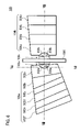
FIGS. 6, 7, and 8 show another example of the light source unit 100. FIG. 6 is a front view of the light source unit 100, FIG. 7 is a vertical sectional view of the light source unit 100 along line VII—VII in FIGS. 6 and 8, and FIG. 8 is a horizontal sectional view of the light source unit 100 along line VIII—VIII in FIGS. 6 and 7. The light source unit 100 according to this example includes a light source retention portion 506, a plurality of light sources 102 a, 102 b and a plurality of reflectors 104 a, 104 b.
The light source retention portion 506 is a substantially flat body, with a front side and a back side which are substantially parallel to and substantially perpendicular to an optical axis of the light source unit 100, and on which the plurality of light sources 102 a, 102 b are respectively retained. The light source retention portion 506 retains the light source 102 a and the light source 102 b so that they face in the lateral direction of the vehicle, and causes light emitted by the plurality of light sources 102 a, 102 b to be incident on the plurality of reflectors 104 a, 104 b, respectively.
The light source 102 a includes a visible light LED 202 a, an infrared light LED 204 a, and a sealing member 214 a. The visible light LED 202 a, the infrared light LED 204 a, and the sealing member 214 a have the same or similar functions as the visible light LED 202, the infrared light LED 204, and the sealing member 214 that were explained with reference to FIGS. 3 and 4.
Surfaces of the visible light LED 202 a and the infrared light LED 204 a are generally square shaped, with approximately 1 mm sides. As shown in FIG. 7, the infrared light LED 204 a is approximately 0.2 mm to the rear of and below the visible light LED 202 a in the longitudinal direction and the vertical direction of the vehicle, respectively. Moreover, as shown in FIG. 8, the infrared light LED 204 a is approximately 0.2 mm closer to the reflector 104 a than the visible light LED 202 a in the lateral direction.
The light source 102 b includes a visible light LED 202 b, an infrared light LED 204 b, and a sealing member 214 b. The infrared light LED 204 b is approximately 0.2 mm closer to the reflector 104 b than the visible light LED 202 b in the lateral direction. With regard to other features, since the light source 102 b has the same or a similar function as the light source 102 a, the explanation thereof will be omitted.
Each of the plurality of reflectors 104 a, 104 b is disposed so as to correspond with a respective one of the respective light sources 102 a, 102 b, facing one another with the light source retention portion 506 interposed therebetween. Based on the visible light emitted by the corresponding light source 102, the plurality of reflectors 104 a, 104 b form an oblique cut-off line and a horizontal cut-off line, respectively, in the light distribution pattern formed by the light source unit 100. The reflectors 104 a, 104 b may have stepped mirrored surfaces.
The reflector 104 a includes a plurality of light distribution steps 502 a to 502 f used in the formation of an oblique cut-off line, which have an optical center F in the vicinity of the visible light LED 202 a. Each of the light distribution steps 502 a to 502 f is a rectangular or inclined trapezoidal segmented portion of the reflector 104 a, and is formed, for example, by a hyperbolic paraboloid whose shape is established in accordance with the shape of the oblique cut-off line to be formed, for example, at individual positions of a predetermined paraboloid of revolution. The hyperbolic paraboloid may have a substantially vertical cross section whose shape conforms to that of a parabola that extends in the forward direction of the light source unit 100, and a generally horizontal cross section whose shape conforms to that of a parabola that extends toward the rear of the light source unit 100, or a curved surface similar thereto.
With the foregoing structure, the reflector 104 a forms a visible light pattern with a predetermined oblique cut-off line as a part of a light distribution pattern formed by the light source unit 100. Also, the reflector 104 a forms an infrared light pattern based on infrared light emitted by the infrared light LED 204 a.
The reflector 104 b includes a plurality of horizontal cut-off line forming steps 504 a to 504 d, each of which is a part of the reflector 104 b and has an optical center F in the vicinity of the visible light LED 202 b. Each of the light distribution steps 504 a to 504 d is formed by a hyperbolic paraboloid which has been set in accordance with the shape of the horizontal cut-off line to be formed. With respect to other features, since the horizontal cut-off line forming light distribution steps 504 have the same or similar configuration and function as the light distribution steps for an oblique cut-off line 502, an explanation thereof will be omitted.
With the foregoing structure, the reflector 104 b forms a visible light pattern with a predetermined horizontal cut-off line as a part of the light distribution pattern formed by the light source unit 100. Also, the reflector 104 b forms an infrared light pattern based on infrared light emitted by the infrared light LED 204 b. According to this example, an appropriate visible light pattern and infrared light pattern can be formed.
Also, it should be noted that, if lens steps for forming light distribution are provided, for example, at a front surface of the light source unit 100 or the vehicular lamp 400 in order to create the desired light distribution pattern, there are some cases where the design of the vehicular lamp would be restricted. According to this example, however, the light distribution pattern is formed by the reflectors 104 a, 104 b. Therefore, such lens steps are not necessary, or else more lens steps with more gradual transitions are sufficient. Therefore, according to this example, it is possible to provide a vehicular headlamp with a highly sophisticated design that offers a smooth appearance from the front surface.
FIG. 9 shows an example of a visible light pattern 304 a formed by the reflector 104 a. In this example, the oblique cut-off line forming light distribution steps 502 a to 502 f form respective segmented visible light patterns 602 a to 602 f which contribute to the visible light pattern 304 a.
The oblique cut-off line forming light distribution steps 502 a forms the segmented visible light pattern 602 a that spreads in the substantially horizontal direction. Further, the oblique cut-off line forming light distribution steps 502 b to 502 f form the segmented visible light patterns 602 b to 602 f, parts of which overlap with the segmented visible light pattern 602 a, which spreads in a predetermined oblique direction. Accordingly, the reflector 104 a forms the visible light pattern 304 a with a desired predetermined oblique cut-off line.
FIG. 10 shows an example of an infrared light pattern 302 a formed by the reflector 104 a. In this example, the oblique cut-off line forming light distribution steps 502 a to 502 f form respective segmented infrared light patterns 702 a to 702 f which contribute to the infrared light pattern 302 a.
In this example, the infrared light LED 204 a is disposed farther than the visible light LED 202 a from the optical center F of the oblique cut-off line forming light distribution steps 502 a to 502 f. Therefore, the oblique cut-off line forming light distribution steps 502 a to 502 f form the respective segmented infrared light patterns 702 a to 702 f, each of which spreads across a wider area than each of the segmented visible light patterns 602 a to 602 f (see FIG. 9). Accordingly, the infrared light pattern 302 a spreads across a wider range than the visible light pattern 304 a.
FIG. 11 shows an example of a visible light pattern 304 b formed by the reflector 104 b. In this example, the horizontal cut-off line forming light distribution steps 504 a to 504 d form respective segmented visible light patterns 604 a to 604 d, which contribute to the visible light pattern 304 d. Accordingly, the reflector 104 b forms the visible light pattern 304 b with a desired predetermined horizontal cut-off line.
FIG. 12 shows an example of an infrared light pattern 302 b formed by the reflector 104 b. In this example, the horizontal cut-off line forming light distribution steps 504 a to 504 d form respective segmented infrared light patterns 704 a to 704 d, which contribute to the infrared light pattern 302 b.
In this example, the infrared light LED 204 b is farther from the optical center F of the horizontal cut-off line forming light distribution steps 504 a to 504 f than the visible light LED 202 b. Therefore, the horizontal cut-off line forming light distribution steps 504 a to 504 d form the segmented infrared light patterns 704 a to 704 d, each of which spreads across a wider region than the segmented visible light patterns 604 a to 604 d (see FIG. 11). As a result, the infrared light spreads across a wider range than the visible light pattern 304 b.
It should be noted that the visible light pattern 304 a, the infrared light pattern 302 a, the visible light pattern 304 b, and the infrared light pattern 302 b that were explained with reference to FIGS. 9 to 12 are low-beam light distribution patterns which are formed on a virtual vertical screen disposed at a position 25 m ahead of the light source unit 100. Also in this example, the infrared light LED 204 and the visible light LED 202 are provided adjacent to each other. Therefore, also in this example, the red light accompanying emission of infrared light can be masked or can be made to appear dimmer because of the white light.
As explained above, the light source unit 100 radiates visible light to the region defined by the predetermined oblique cut-off line and horizontal cut-off line by forming the visible light patterns 304 a, 304 b. Moreover, the light source unit 100 radiates infrared light over a wider area than it radiates visible light by forming the infrared light patterns 302 a, 302 b. Therefore, according to this example, an appropriate light distribution pattern can be formed. Accordingly, it is possible to provide a highly advanced vehicular headlamp capable of radiating both visible light and infrared light.
As is apparent from the explanation above, a highly advanced vehicular headlamp can be provided at low cost according to the present invention.
While the present invention has been described with reference to some embodiments, the technical scope of the present invention is not so limited, and various modifications are possible. Such modifications are included in the technical scope of the present invention as defined by the claims.

Claims (20)

1. A vehicular headlamp for use in vehicles, said headlamp comprising:
a first semiconductor light-emitting element for emitting visible light;
a reflector having an optical center in the vicinity of the first semiconductor light-emitting element and forming at least a part of a light distribution pattern of the vehicular head-lamp by reflecting the visible light; and
a second semiconductor light-emitting element for emitting infrared light, said second semiconductor light-emitting element being disposed at a position different from that of the first semiconductor light-emitting element and which emits infrared light which the reflector also reflects.
wherein the first semiconductor light-emitting element and second semiconductor light-emitting element are mounted on a single base board.
2. The vehicular headlamp according to claim 1, wherein:
the vehicular headlamp radiates the visible light forwardly of the vehicle,
the vehicular headlamp further includes a sealing member comprising a material that transmits the visible light and the infrared light and integrally houses and seals the first and second semiconductor light-emitting elements, and
the reflector reflects the visible light and the infrared light forwardly of the vehicle.
3. The vehicular headlamp according to claim 2, wherein:
the vehicular headlamp emits the infrared light at a greater elevational angle than that of the visible light.
4. The vehicular headlamp according to claim 2, further comprising a fluorescent body covering the first semiconductor light-emitting element.
5. The vehicular headlamp according to claim 4, wherein the fluorescent body comprises material with light transmission characteristics that are complementary to the light emission characteristics of the first semiconductor light-emitting element, so that substantially white light emerges from the fluorescent body.
6. The vehicular headlamp according to claim 1, wherein the reflector comprises a hyperbolic paraboloid.
7. The vehicular headlamp according to claim 1, wherein the first semiconductor light-emitting element comprises a red light-emitting diode, a green light-emitting diode, and a blue light-emitting diode, so as to enable the first semiconductor light-emitting element to emit substantially white light.
8. The vehicular headlamp according to claim 1, wherein the second semiconductor light-emitting element also emits red light near a range of the infrared light, and wherein the first and second semiconductor light-emitting elements are disposed relative to each other, and relative to the reflector, such that the only visible light coming from the headlamp is substantially white light.
9. The vehicular headlamp according to claim 1, wherein:
the vehicular headlamp radiates the visible light forwardly of the vehicle,
the reflector comprises a mirrored surface which extends from the rear of the first semiconductor light-emitting element in the forward direction so as to cover the first semiconductor light-emitting element for visible light, and to reflect the visible light forwardly of the vehicle, and
the second semiconductor light-emitting element is disposed between the first semiconductor light-emitting element and a rear end of the reflector.
10. The vehicular headlamp according to claim 1, wherein:
the second semiconductor light-emitting element is farther from the optical center of the reflector than the first semiconductor light-emitting element.
11. A light-emitting module for a headlamp for a vehicle, the module comprising:
a first semiconductor light-emitting element for emitting visible light;
a second semiconductor light-emitting element for emitting infrared light; and
a sealing member which integrally houses and seals the first and second semiconductor light-emitting elements, said sealing member comprising a material that transmits both the visible light and the infrared light, such that the module emits light forwardly of the vehicle.
12. A vehicular headlamp for use in vehicles, said headlamp comprising at least two light-emitting modules, each of said modules comprising:
a first semiconductor light-emitting element for emitting visible light;
a second semiconductor light-emitting element for emitting infrared light; and
a sealing member which integrally houses and seals the first and second semiconductor light-emitting elements, said sealing member comprising a material that transmits both the visible light and the infrared light, such that the module emits light forwardly of the vehicle.
13. The vehicular headlamp according to claim 12, further comprising a substantially flat light retention portion having the first and second light-emitting modules disposed respectively on opposing substantially flat surfaces thereof, and respective first and second pluralities of reflectors for reflecting light emitted from the respective first and second light-emitting modules.
14. The vehicular headlamp according to claim 13, wherein the first and second pluralities of reflectors comprise respective pluralities of stepped mirrored surfaces, providing respective pluralities of light distribution steps for light emitted by the respective first and second light-emitting modules.
15. The vehicular headlamp according to claim 13, wherein, in each of said first and second light-emitting modules, the second semiconductor light-emitting element is farther from the optical center of its respective reflector than is the first semiconductor light-emitting element.
16. The vehicular headlamp according to claim 1, wherein the reflector reflects the visible light and the infrared light forwardly of the vehicle.
17. The vehicular headlamp according to claim 1, wherein the second semiconductor light-emitting element is arranged with respect to the first semiconductor light-emitting element and the reflector so that the vehicular headlamp emits infrared light over a larger area than visible light.
18. The vehicular headlamp according to claim 1, further comprising a sealing member which integrally houses and seals the first and second semiconductor light-emitting elements.
19. The vehicular headlamp according to claim 18, wherein the sealing member is constructed of a material that transmits visible light and infrared light, and fills a volume between the first semiconductor light-emitting element and the second semiconductor light-emitting element.
20. The vehicular headlamp according to claim 2, wherein the sealing member fills a volume between the first semiconductor light-emitting element and the second semiconductor light-emitting element.
US10/769,990 2003-02-03 2004-02-03 Vehicular headlamp and light-emitting module therefor Active 2024-06-09 US7134775B2 (en)

Applications Claiming Priority (2)

Application Number Priority Date Filing Date Title
JPP.2003-025953 2003-02-03
JP2003025953A JP4094446B2 (en) 2003-02-03 2003-02-03 Vehicle headlamp and light emitting module

Publications (2)

Publication Number Publication Date
US20040240219A1 US20040240219A1 (en) 2004-12-02
US7134775B2 true US7134775B2 (en) 2006-11-14

Family

ID=32954102

Family Applications (1)

Application Number Title Priority Date Filing Date
US10/769,990 Active 2024-06-09 US7134775B2 (en) 2003-02-03 2004-02-03 Vehicular headlamp and light-emitting module therefor

Country Status (2)

Country Link
US (1) US7134775B2 (en)
JP (1) JP4094446B2 (en)

Cited By (12)

* Cited by examiner, † Cited by third party
Publication number Priority date Publication date Assignee Title
US20060002130A1 (en) * 2004-06-24 2006-01-05 Pierre Albou Lighting module for a motor vehicle and a light comprising such a module
US20060109672A1 (en) * 2004-11-24 2006-05-25 Koito Manufacturing Co., Ltd. Lighting fixture unit and vehicular headlamp
US20060209270A1 (en) * 2005-03-15 2006-09-21 Casio Computer Co., Ltd. Light source apparatus that collects and provides different-colored light rays emitted by a plurality of different-colored light sources and a projector comprising such light source apparatus
US20070279924A1 (en) * 2006-05-31 2007-12-06 Koito Manufacturing Co., Ltd. Vehicular lamp unit
US20080151567A1 (en) * 2006-12-20 2008-06-26 Valeo Vision Motor vehicle headlight module for a cutoff beam
US20090097247A1 (en) * 2007-10-12 2009-04-16 Tseng Jui-Huang Led lamp
US20100046241A1 (en) * 2008-08-19 2010-02-25 Honeywell International Inc. Systems and methods for aircraft led anti collision light
US20100060127A1 (en) * 2008-09-08 2010-03-11 Koito Manufacturing Co., Ltd. Vehicular infrared irradiation lamp
US20100277939A1 (en) * 2009-04-30 2010-11-04 Koito Manufacturing Co., Ltd. Vehicular lamp
CN102954422A (en) * 2011-08-17 2013-03-06 汽车照明罗伊特林根有限公司 Motor vehicle lighting device
US20150303356A1 (en) * 2014-04-18 2015-10-22 Nichia Corporation Semiconductor light emitting device and method of manufacturing the same
US9638388B2 (en) * 2011-02-09 2017-05-02 Truck-Lite Co., Llc Headlamp assembly with heat sink structure

Families Citing this family (38)

* Cited by examiner, † Cited by third party
Publication number Priority date Publication date Assignee Title
JP4200849B2 (en) * 2003-07-17 2008-12-24 日産自動車株式会社 Infrared projector for vehicles
EP1780592A4 (en) * 2004-06-30 2014-07-09 Mitsubishi Chem Corp Light emitting device, backlight unit for lighting, display unit and display unit
DE102004047324A1 (en) * 2004-09-29 2006-04-13 Osram Opto Semiconductors Gmbh LED array
JP4258465B2 (en) * 2004-12-01 2009-04-30 市光工業株式会社 Vehicle headlamp unit
DE102005041065A1 (en) * 2005-02-16 2006-08-24 Patent-Treuhand-Gesellschaft für elektrische Glühlampen mbH lighting device
US7270449B2 (en) * 2005-02-17 2007-09-18 Alan Uke Lighting system and method and reflector for use in same
JP4655751B2 (en) * 2005-05-10 2011-03-23 トヨタ自動車株式会社 Irradiation device and night vision device
JP4597788B2 (en) * 2005-06-16 2010-12-15 富士重工業株式会社 Infrared projector
ITMI20051492A1 (en) * 2005-07-29 2007-01-30 Ecie S R L LED LIGHTING DEVICE WITH ORTHOGONAL OPTICAL AXIS TO THE OPTICAL AXIS OF THE SAME DEVICE
DE102006019287A1 (en) * 2006-04-26 2007-10-31 Bayerische Motoren Werke Ag Motor vehicle headlight, has base light source and infrared light source such as infrared LED supported by rotatable mounting device that has housing, which surrounds base light source
US8410402B2 (en) * 2006-08-28 2013-04-02 Dialight Corporation Method and apparatus for using light emitting diodes for removing moisture
DE102006041942A1 (en) * 2006-09-07 2008-03-27 Hella Kgaa Hueck & Co. Projection headlight for vehicle, has reflector devices extending in area between extension level of respective light source device and optical axis of lens, where light source devices are attached to respective reflector devices
DE102006059592A1 (en) * 2006-12-16 2008-06-19 Bayerische Motoren Werke Ag Automobile headlights
DE102007015233A1 (en) * 2007-03-29 2008-10-02 Osram Gesellschaft mit beschränkter Haftung LED lamp for e.g. motor vehicle light, has LED emitting visible light, and radiation-emitting semiconductor component emitting electromagnetic radiation with maximum intensity outside visible spectral region
DE102007026780B4 (en) * 2007-06-09 2011-07-07 Automotive Lighting Reutlingen GmbH, 72762 Radiation source for an active infrared night vision device
JP2009184410A (en) * 2008-02-04 2009-08-20 Koito Mfg Co Ltd Vehicular lighting fixture
JP4617367B2 (en) 2008-03-13 2011-01-26 シャープ株式会社 Headlamp and vehicle infrared night vision apparatus using the same as a light source
JP5271590B2 (en) * 2008-04-22 2013-08-21 株式会社小糸製作所 Vehicle lighting
JP5582380B2 (en) * 2009-03-24 2014-09-03 スタンレー電気株式会社 Vehicle lighting
JP5133861B2 (en) * 2008-12-09 2013-01-30 株式会社小糸製作所 Lighting fixtures for vehicles
JP5133862B2 (en) * 2008-12-09 2013-01-30 株式会社小糸製作所 Lighting fixtures for vehicles
JP5210180B2 (en) * 2009-01-14 2013-06-12 スタンレー電気株式会社 Vehicle headlamp
JP5406766B2 (en) * 2010-03-23 2014-02-05 株式会社小糸製作所 Vehicle headlamp
US8556473B2 (en) 2010-06-30 2013-10-15 Osram Sylvania Inc. Lamp with a truncated reflector cup
DE102011004293B4 (en) 2010-09-23 2023-03-02 Automotive Lighting Reutlingen Gmbh Motor vehicle headlight with an infrared emitter
JP5666934B2 (en) * 2011-02-03 2015-02-12 株式会社小糸製作所 Optical unit and vehicle lamp
JP5811675B2 (en) * 2011-08-09 2015-11-11 市光工業株式会社 Vehicle lighting
JP5880951B2 (en) * 2012-03-14 2016-03-09 スタンレー電気株式会社 Vehicle headlamp
JP2014212089A (en) * 2013-04-22 2014-11-13 株式会社小糸製作所 Vehicular lighting tool
JP6162497B2 (en) * 2013-06-21 2017-07-12 株式会社小糸製作所 Lamp unit and vehicle lamp
EP2837566B1 (en) * 2013-08-13 2019-10-02 Goodrich Lighting Systems GmbH Exterior aircraft light unit and aircraft comprising the exterior aircraft light unit
KR101606772B1 (en) * 2013-11-22 2016-03-28 현대모비스 주식회사 Multi-Array LED Chip for vehicle and Head lamp having the same
JP6751307B2 (en) * 2016-05-17 2020-09-02 スタンレー電気株式会社 Vehicle lighting
JP6914584B2 (en) * 2016-12-27 2021-08-04 ダイハツ工業株式会社 Lamp
EP3376095B1 (en) * 2017-03-14 2019-08-21 Yamaha Hatsudoki Kabushiki Kaisha Low-beam-color-temperature-variable headlight unit
DE102017117591A1 (en) * 2017-08-03 2019-02-07 Automotive Lighting Reutlingen Gmbh Automotive headlamp arrangement
US10908334B2 (en) * 2019-04-19 2021-02-02 Lumileds Llc Mitigation of perceived redness of infrared light
US11906124B2 (en) 2021-06-08 2024-02-20 Apple Inc. Multiband adjustable lights

Citations (11)

* Cited by examiner, † Cited by third party
Publication number Priority date Publication date Assignee Title
JPH0610880U (en) 1992-07-10 1994-02-10 スタンレー電気株式会社 LED light fixture with proximity sensor
US5633710A (en) * 1995-10-04 1997-05-27 Egs Inc. System for self-aligning vehicle headlamps
JPH1021703A (en) 1996-05-02 1998-01-23 Patoraito:Kk Led illuminator
US6250788B1 (en) * 1997-11-29 2001-06-26 Volkswagen Ag Motor vehicle light arrangement
JP2001229719A (en) 2000-02-15 2001-08-24 Marumo Denki Kk Spotlight
US6296376B1 (en) * 1998-08-12 2001-10-02 Stanley Electric Co., Ltd. Led lamp having a prismatically-cut modifier
JP2002021993A (en) 2000-07-10 2002-01-23 Nissan Motor Co Ltd Hydraulic control circuit of automatic transmission for vehicle with automatic stop engine
US6520669B1 (en) * 2000-06-19 2003-02-18 Light Sciences Corporation Flexible substrate mounted solid-state light sources for exterior vehicular lighting
US6565247B2 (en) * 2000-03-01 2003-05-20 Robert Bosch Gmbh Illumination device for vehicle
US6601980B2 (en) 2000-02-15 2003-08-05 Koito Manufacturing Co., Ltd. Infrared-ray radiating lamp for automobile
US20040042212A1 (en) * 2002-08-30 2004-03-04 Gelcore, Llc Led planar light source and low-profile headlight constructed therewith

Patent Citations (11)

* Cited by examiner, † Cited by third party
Publication number Priority date Publication date Assignee Title
JPH0610880U (en) 1992-07-10 1994-02-10 スタンレー電気株式会社 LED light fixture with proximity sensor
US5633710A (en) * 1995-10-04 1997-05-27 Egs Inc. System for self-aligning vehicle headlamps
JPH1021703A (en) 1996-05-02 1998-01-23 Patoraito:Kk Led illuminator
US6250788B1 (en) * 1997-11-29 2001-06-26 Volkswagen Ag Motor vehicle light arrangement
US6296376B1 (en) * 1998-08-12 2001-10-02 Stanley Electric Co., Ltd. Led lamp having a prismatically-cut modifier
JP2001229719A (en) 2000-02-15 2001-08-24 Marumo Denki Kk Spotlight
US6601980B2 (en) 2000-02-15 2003-08-05 Koito Manufacturing Co., Ltd. Infrared-ray radiating lamp for automobile
US6565247B2 (en) * 2000-03-01 2003-05-20 Robert Bosch Gmbh Illumination device for vehicle
US6520669B1 (en) * 2000-06-19 2003-02-18 Light Sciences Corporation Flexible substrate mounted solid-state light sources for exterior vehicular lighting
JP2002021993A (en) 2000-07-10 2002-01-23 Nissan Motor Co Ltd Hydraulic control circuit of automatic transmission for vehicle with automatic stop engine
US20040042212A1 (en) * 2002-08-30 2004-03-04 Gelcore, Llc Led planar light source and low-profile headlight constructed therewith

Cited By (23)

* Cited by examiner, † Cited by third party
Publication number Priority date Publication date Assignee Title
US7682057B2 (en) * 2004-06-24 2010-03-23 Valeo Vision Lighting module for a motor vehicle and a light comprising such a module
US20060002130A1 (en) * 2004-06-24 2006-01-05 Pierre Albou Lighting module for a motor vehicle and a light comprising such a module
US20060109672A1 (en) * 2004-11-24 2006-05-25 Koito Manufacturing Co., Ltd. Lighting fixture unit and vehicular headlamp
US7370998B2 (en) * 2004-11-24 2008-05-13 Koito Manufacturing Co., Ltd. Lighting fixture unit and vehicular headlamp
US20060209270A1 (en) * 2005-03-15 2006-09-21 Casio Computer Co., Ltd. Light source apparatus that collects and provides different-colored light rays emitted by a plurality of different-colored light sources and a projector comprising such light source apparatus
US7744225B2 (en) * 2005-03-15 2010-06-29 Casio Computer Co., Ltd. Light source apparatus that collects and provides different-colored light rays emitted by a plurality of different-colored light sources and a projector comprising such light source apparatus
US20070279924A1 (en) * 2006-05-31 2007-12-06 Koito Manufacturing Co., Ltd. Vehicular lamp unit
US7553054B2 (en) * 2006-05-31 2009-06-30 Koito Manufacturing Co., Ltd. Vehicular lamp unit
US20080151567A1 (en) * 2006-12-20 2008-06-26 Valeo Vision Motor vehicle headlight module for a cutoff beam
US7934861B2 (en) * 2006-12-20 2011-05-03 Valeo Vision Motor vehicle headlight module for a cutoff beam
US20090097247A1 (en) * 2007-10-12 2009-04-16 Tseng Jui-Huang Led lamp
US20100046241A1 (en) * 2008-08-19 2010-02-25 Honeywell International Inc. Systems and methods for aircraft led anti collision light
US8123377B2 (en) * 2008-08-19 2012-02-28 Honeywell International Inc. Systems and methods for aircraft LED anti collision light
US8292479B2 (en) * 2008-09-08 2012-10-23 Koito Manufacturing Co., Ltd. Vehicular infrared irradiation lamp
US20100060127A1 (en) * 2008-09-08 2010-03-11 Koito Manufacturing Co., Ltd. Vehicular infrared irradiation lamp
US20100277939A1 (en) * 2009-04-30 2010-11-04 Koito Manufacturing Co., Ltd. Vehicular lamp
US9080738B2 (en) * 2009-04-30 2015-07-14 Koito Manufacturing Co., Ltd. Vehicular lamp
US9638388B2 (en) * 2011-02-09 2017-05-02 Truck-Lite Co., Llc Headlamp assembly with heat sink structure
CN102954422A (en) * 2011-08-17 2013-03-06 汽车照明罗伊特林根有限公司 Motor vehicle lighting device
US20130201712A1 (en) * 2011-08-17 2013-08-08 Kamislav Fadel Motor vehicle lighting device
US20150303356A1 (en) * 2014-04-18 2015-10-22 Nichia Corporation Semiconductor light emitting device and method of manufacturing the same
US9397270B2 (en) * 2014-04-18 2016-07-19 Nichia Corporation Semiconductor light emitting device and method of manufacturing the same
US9620689B2 (en) * 2014-04-18 2017-04-11 Nichia Corporation Semiconductor light emitting device and method of manufacturing the same

Also Published As

Publication number Publication date
US20040240219A1 (en) 2004-12-02
JP4094446B2 (en) 2008-06-04
JP2004241138A (en) 2004-08-26

Similar Documents

Publication Publication Date Title
US7134775B2 (en) Vehicular headlamp and light-emitting module therefor
EP2019257B1 (en) Vehicle lighting assembly and light guiding lens for use n vehicle lighting assembly
JP4937649B2 (en) Vehicle lighting
US9188297B2 (en) Automotive headlamp forming multiple light distribution patterns with a single lamp
JP6207874B2 (en) Lamp unit for vehicle lamp
US7207703B2 (en) Headlamp unit for vehicle and headlamp unit assembly
US8162507B2 (en) Lamp unit having a parabola optical system reflector
US7114828B2 (en) Vehicular headlamp
US7131759B2 (en) Vehicular lamp and light source module
US7997779B2 (en) Vehicle lamp unit
US8864351B2 (en) Vehicle headlamp
US8960978B2 (en) Vehicular lamp
US9506613B2 (en) Vehicle lamp fitting
JP2010050008A (en) Lighting fixture
US10612743B2 (en) Vehicle lamp
US20140022804A1 (en) Vehicle lighting unit
JP5444046B2 (en) Vehicle headlamp
JP6340696B2 (en) Lighting device and automobile
EP2570715A2 (en) Vehicle headlamp
JP6064439B2 (en) Vehicle headlamp
US7543963B2 (en) Module for projecting a light beam
JP2006339008A (en) Vehicle lamp
CN104654169A (en) Vehicular Lamp
US11221122B2 (en) Lighting device and headlight having a reflector, lenses and light-shielding members
JP6920015B2 (en) Vehicle lighting

Legal Events

Date Code Title Description
AS Assignment

Owner name: KOITO MANUFACTURING CO., LTD, JAPAN

Free format text: ASSIGNMENT OF ASSIGNORS INTEREST;ASSIGNORS:OISHI, KAZUTAMI;SAZUKA, KIYOSHI;REEL/FRAME:015627/0393

Effective date: 20040311

STCF Information on status: patent grant

Free format text: PATENTED CASE

FEPP Fee payment procedure

Free format text: PAYOR NUMBER ASSIGNED (ORIGINAL EVENT CODE: ASPN); ENTITY STATUS OF PATENT OWNER: LARGE ENTITY

FPAY Fee payment

Year of fee payment: 4

FPAY Fee payment

Year of fee payment: 8

MAFP Maintenance fee payment

Free format text: PAYMENT OF MAINTENANCE FEE, 12TH YEAR, LARGE ENTITY (ORIGINAL EVENT CODE: M1553)

Year of fee payment: 12