EP1597778B1 - Protective housing for a ceramic actuator - Google Patents
Protective housing for a ceramic actuator Download PDFInfo
- Publication number
- EP1597778B1 EP1597778B1 EP04714370A EP04714370A EP1597778B1 EP 1597778 B1 EP1597778 B1 EP 1597778B1 EP 04714370 A EP04714370 A EP 04714370A EP 04714370 A EP04714370 A EP 04714370A EP 1597778 B1 EP1597778 B1 EP 1597778B1
- Authority
- EP
- European Patent Office
- Prior art keywords
- actuator
- housing
- housing according
- protective structure
- compliant
- Prior art date
- Legal status (The legal status is an assumption and is not a legal conclusion. Google has not performed a legal analysis and makes no representation as to the accuracy of the status listed.)
- Expired - Lifetime
Links
- 230000001681 protective effect Effects 0.000 title claims abstract description 45
- 239000000919 ceramic Substances 0.000 title claims abstract description 15
- 238000006073 displacement reaction Methods 0.000 claims abstract description 24
- 239000000463 material Substances 0.000 claims description 18
- 239000006260 foam Substances 0.000 claims description 5
- 238000000465 moulding Methods 0.000 claims description 5
- 238000000034 method Methods 0.000 claims description 3
- 239000000725 suspension Substances 0.000 abstract description 18
- 238000004804 winding Methods 0.000 description 12
- 229910052451 lead zirconate titanate Inorganic materials 0.000 description 4
- 239000004033 plastic Substances 0.000 description 3
- 229920003023 plastic Polymers 0.000 description 3
- 238000005452 bending Methods 0.000 description 2
- 238000010276 construction Methods 0.000 description 2
- 230000001747 exhibiting effect Effects 0.000 description 2
- HFGPZNIAWCZYJU-UHFFFAOYSA-N lead zirconate titanate Chemical compound [O-2].[O-2].[O-2].[O-2].[O-2].[Ti+4].[Zr+4].[Pb+2] HFGPZNIAWCZYJU-UHFFFAOYSA-N 0.000 description 2
- 238000004519 manufacturing process Methods 0.000 description 2
- 229910052751 metal Inorganic materials 0.000 description 2
- 239000002184 metal Substances 0.000 description 2
- 230000003287 optical effect Effects 0.000 description 2
- -1 polypropylene Polymers 0.000 description 2
- 239000011347 resin Substances 0.000 description 2
- 229920005989 resin Polymers 0.000 description 2
- 238000003462 Bender reaction Methods 0.000 description 1
- 239000004677 Nylon Substances 0.000 description 1
- 239000004952 Polyamide Substances 0.000 description 1
- 239000004698 Polyethylene Substances 0.000 description 1
- 239000004743 Polypropylene Substances 0.000 description 1
- 229920005830 Polyurethane Foam Polymers 0.000 description 1
- 238000004026 adhesive bonding Methods 0.000 description 1
- 229910010293 ceramic material Inorganic materials 0.000 description 1
- 230000000295 complement effect Effects 0.000 description 1
- 239000011263 electroactive material Substances 0.000 description 1
- 239000002360 explosive Substances 0.000 description 1
- 238000002347 injection Methods 0.000 description 1
- 239000007924 injection Substances 0.000 description 1
- 229910001092 metal group alloy Inorganic materials 0.000 description 1
- 229910044991 metal oxide Inorganic materials 0.000 description 1
- 150000004706 metal oxides Chemical class 0.000 description 1
- 150000002739 metals Chemical class 0.000 description 1
- 229920001778 nylon Polymers 0.000 description 1
- 238000001259 photo etching Methods 0.000 description 1
- 229920002647 polyamide Polymers 0.000 description 1
- 229920001690 polydopamine Polymers 0.000 description 1
- 229920000573 polyethylene Polymers 0.000 description 1
- 229920001155 polypropylene Polymers 0.000 description 1
- 239000011496 polyurethane foam Substances 0.000 description 1
- 239000004065 semiconductor Substances 0.000 description 1
- 230000035945 sensitivity Effects 0.000 description 1
- 238000000926 separation method Methods 0.000 description 1
- 230000035939 shock Effects 0.000 description 1
Images


Classifications
-
- G—PHYSICS
- G02—OPTICS
- G02B—OPTICAL ELEMENTS, SYSTEMS OR APPARATUS
- G02B7/00—Mountings, adjusting means, or light-tight connections, for optical elements
- G02B7/02—Mountings, adjusting means, or light-tight connections, for optical elements for lenses
- G02B7/04—Mountings, adjusting means, or light-tight connections, for optical elements for lenses with mechanism for focusing or varying magnification
-
- H—ELECTRICITY
- H01—ELECTRIC ELEMENTS
- H01L—SEMICONDUCTOR DEVICES NOT COVERED BY CLASS H10
- H01L21/00—Processes or apparatus adapted for the manufacture or treatment of semiconductor or solid state devices or of parts thereof
- H01L21/02—Manufacture or treatment of semiconductor devices or of parts thereof
-
- H—ELECTRICITY
- H10—SEMICONDUCTOR DEVICES; ELECTRIC SOLID-STATE DEVICES NOT OTHERWISE PROVIDED FOR
- H10N—ELECTRIC SOLID-STATE DEVICES NOT OTHERWISE PROVIDED FOR
- H10N30/00—Piezoelectric or electrostrictive devices
- H10N30/80—Constructional details
- H10N30/88—Mounts; Supports; Enclosures; Casings
-
- H—ELECTRICITY
- H10—SEMICONDUCTOR DEVICES; ELECTRIC SOLID-STATE DEVICES NOT OTHERWISE PROVIDED FOR
- H10N—ELECTRIC SOLID-STATE DEVICES NOT OTHERWISE PROVIDED FOR
- H10N30/00—Piezoelectric or electrostrictive devices
- H10N30/20—Piezoelectric or electrostrictive devices with electrical input and mechanical output, e.g. functioning as actuators or vibrators
- H10N30/204—Piezoelectric or electrostrictive devices with electrical input and mechanical output, e.g. functioning as actuators or vibrators using bending displacement, e.g. unimorph, bimorph or multimorph cantilever or membrane benders
- H10N30/2041—Beam type
- H10N30/2042—Cantilevers, i.e. having one fixed end
Definitions
- This invention relates to actuators in particular ceramic actuators which may be electro-active, for example piezoelectric.
- This invention relates to a housing for such actuators which may be applied to a camera in which the actuator moves a lens holder. It may be applied to micro-cameras in portable data processing or communicating devices.
- Piezoelectric and other electro-active benders made from ceramic base material such as lead zirconate titanate (PZT) are used in many applications. They are manufactured for example from multilayer (green) material and sintered at high temperatures into their final shape.
- Small electro-active actuators with comparably large translation displacements have been recently build using a structure of piezoelectric bender tape extending helically around an axis which is itself curved, as described, for example, in WO-01/47041 or D. H. Pearce et al., Sensors and Actuators A 100 (2002), 281 -286.
- Such devices are capable of exhibiting displacement in the order of millimetres on an active length of the order of centimetres. They may be manufactured from multilayer ceramic base material such as lead zirconate titanate (PZT) and sintered at high temperatures into their final shape.
- PZT lead zirconate titanate
- Lens suspensions systems which constrain the motion of the lens holder, have to co-evolve.
- Lens suspension systems suitable for miniaturized cameras, particularly for cameras driven by an electro-active transducer ideally have a low stiffness, resistive force or friction in direction of the desired motion and high stiffness in all other directions.
- a housing in which there is mounted a ceramic actuator which is a bender extending in a helix around an axis which is curved, the housing having a protective structure comprising a continuous sloping ramp having a compliant portion facing the actuator and being arranged to limit the range of motion of said actuator by contacting a middle section of said actuator between fixed and moving terminals of said actuator.
- An actuator is typically operated with a fixed terminal or end section and a moving terminal or end section.
- the fixed terminal is attached to the housing or mounted on a base structure shared with the housing.
- the moving terminal of the actuator is the section of the actuator that displays the largest displacement relative to the fixed section of the actuator.
- the protective structure is adapted to limit the range of displacement of the actuator by contacting the actuator at a middle section located between the two terminal sections of the actuator.
- the actuator is free to move, on actuation, within the range of displacement until it contacts the protective structure and references to contacting should be understood accordingly.
- Such a protective structure protects the actuator against a sudden impact, as caused for example by a drop onto a hard surface, by preventing excessive displacement of the actuator which would cause damage.
- the present invention is used to house actuators capable of relatively large displacement, such as the actuators of the type mentioned above and disclosed in WO-0147041 or D. H. Pearce et al., Sensors and Actuators A 100 (2002), 281 -286, such actuators being particularly susceptable to damage from a sudden impact.
- the portion of protective structure adapted to contact the actuator is compliant, for example by being formed by a layer of compliant material or by a plurality of discrete resilient elements, so as to be capable of absorbing the kinetic energy of the actuator.
- the compliant portion is a plurality of discrete resilient elements adapted to contact the actuator
- the elements may be resilient members such as mechanical spring type structures for removal of energy from the actuator on impact.
- Suitable structures include for example resilient beams disposed along the protective structure.
- the protective structure is placed outside the nominal range of displacement.
- the nominal range of displacement of the actuator is the displacement exhibited by the actuator during normal operating conditions.
- the limits of the nominal range of displacement define a surface or an envelope outside which the protective structure is located.
- the protective structure follows the contour defined by the limits of the nominal range of displacement.
- the protective structure may be arranged to have an approximately constant distance from the limits of the nominal range of displacement at different points along the actuator.
- the protective housing of the invention may be readily manufactured for example by moulding of plastic materials.
- the protective structure may be advantageously moulded in one piece with the housing.
- a compliant layer if provided, may be attached for example by glueing to the protective structure.
- the compliant layer or layers may be incorporated in the housing during manufacture by two-shot moulding, in which the housing and compliant layers are produced in different materials within the same mould.
- Resilient structures such as resilient beams may be advantageously moulded in one piece with the housing, forming the appropriate ramp contour.
- spring structures may be cut from thin metal sheet, for example by photo-chemical etching, bent to the appropriate shape if necessary, and then fixed into the housing, preferably by means of moulded locating pips in the housing.
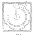
- Figs. 1 and 2 show a camera assembly having a protective housing 20, shown in both a vertical cross-section (Fig. 1) and a horizontal cross-section (Fig. 2).
- the actuator 21 comprises a piezoelectric multi-layer, bender tape, for example of a bimorph construction, extending helically around an axis which is itself curved, as described, for example, in WO-01/47041 or D. H. Pearce et al., Sensors and Actuators A 100 (2002), 281-286, the teachings of which may be applied to the present invention.
- the actuator 21 comprises a tape wound helically around a first axis, referred to as the minor axis.
- the helically wound portion is further coiled into a secondary winding of about three quarters of a complete turn.
- the axis of this secondary winding is referred to as the major axis.
- the first winding is known as the primary winding or primary helix.
- the secondary winding is about three-quarters of a complete turn, in general, the secondary winding could be any curve and could exceed one turn and form a spiral or secondary helix. It is therefore usually referred to as secondary curve.
- the tape is arranged on actuation to bend around the minor axis. Due to the helical curve around the minor axis, such bending is concomitant with twisting of the actuator 21 around the minor axis. Due to the curve around the major axis, such twisting is concomitant with relative displacement of the ends 211, 212 of the actuator 21.
- the proximate end 211 of the actuator 21 is fixed to the housing 20.
- This type of lens suspension and actuations system are described in greater detail in WO-02/103451 and WO-03/048831,
- the housing of the present example includes a protective structure 25 in the form of two sloping surfaces or ramps arranged above and below the actuator 21 approximately following the contours of the upper and lower limits, respectively, of the nominal displacement of the actuator 21, that is the displacement exhibited by the actuator 21 during normal operating conditions, thereby limiting the motion of the actuator 21.
- This protective structure 25 is covered with foam layers 251 facing the actuator 21 so as to come into contact with the moving actuator 21.
- the housing 20 has end stops 201 arranged to limit the motion of the lens barrel 22.
- the actuator 21 can be regarded as being momentarily fixed to the housing 20 at both ends.
- the remaining sections of the actuator 21 continue to move, thus potentially causing, in the absence of the protective structure 25, damage to its ceramic material.
- the actuator 21 with its middle section contacts the protective structure 25 the motion of the actuator 21 is limited and the kinetic energy of the actuator 21 is absorbed by the foam layer 251, so the risk of damage is consequently reduced.
- the protective structure 25, 251 is shaped such that, in the event of an impact, the actuator 21 contacts approximately evenly along its length. In the example, it bends into half a turn above and below the secondary turn of the actuator 21.
- the contact surface 251 of the protective structure may be shaped convex to provide a broader area of contact with the outer circumference of the actuator.
- the advantage of a continuous or quasi-continuous support is shown by reference to the following table which, for the case of a protective structure of discrete elements, lists the length of actuator sections between the discrete elements (or in other words the relative separation between neighboring discrete elements) and the maximum stopping force that can be applied to the actuator section before causing damage to it. Length of unsupported sections between two supports (relative units) Maximum Force (N) Distance (mm) 4 0.35 7.3 3 0.46 4.1 2 0.7 1.8 1 1.4 0.45
- the stopping distance can be calculated. It is apparent from the table that closer points of contact, and in the limit continuous contact, is better to stop the actuator before it reaches its breaking point.
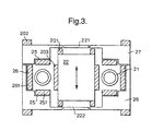
- Fig. 3 shows a vertical cross-section of a further camera assembly in a protective housing.
- the camera assembly is similar to that of Figs. 1 and 2, so common elements are given the same reference numerals and a description thereof is not repeated.
- the camera assembly has an actuator 21 of the same type as in Fig. 1.
- the actuator 21 is attached to a lens barrel 22 and to a housing (attachments not shown) which in this case comprises two parts, namely a bottom housing 26 and a top housing 27.
- a transparent cover 221 and image sensor 222 are shown above and below the lens barrel in the top and bottom housings 27,26 respectively.
- a protective structure 25 takes the form of sloping surfaces or ramps which follow the actuator 21 from above and below and are faced with compliant material 251. Additional protection is provided at the inside of the bottom housing 28 in the form of compliant pads 281, to afford protection against sideways motion.
- Each part 26, 27 of this housing may be manufuctured by a two shot moulding process, in which the housing parts 26, 27, and the compliant material 251 and the compliant pads 28 are formed together in the same moulding process
- the top housing 27 may be produced by first forming the compliant pads 251 by a first shot of resin into a suitable mould, and then forming the housing 27 on top of the pads 251 with a second shot of (different) resin.
- the bottom housing 26 may be moulded in two shots, one for the compliant pads 251,281 and one for the more rigid housing structure 26.
- Fig. 3 also shows further protection for the lens and actuator system, in the form of end stops 201 for the lens barrel, end stops 202 for the complete assembly, and a protective pad 203 around the lens barrel.
- additional protective features may be moulded integrally with the housing or lens barrel elements, as above.
- the assembly of Fig. 3 provides comprehensive shock protection for its functional elements (actuator 21 and lens barrel 22) and can be readily and cheaply mass manufactured.
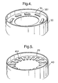
- Figs. 4 to 7 show perspective views of alternative protective structures which may be used in place of the protective structure 25 shown in Figs. 1 to 3.
- the compliant foam layer 251 of Figs. 1 to 3 is replaced by a plurality of discrete, resilient elements in the form of mechanical spring structures, serving to remove energy from the moving actuator on impact.
- Figs. 4 to 7 show the lower protective structure, the upper protective structure being a mirror image thereof.
- Fig. 4 shows a partial perspective view of such a protective structure 35 incorporating a spring structure 351 within a housing 30, for protection of a ceramic actuator and lens barrel assembly (not shown) similar to those in Fig. 1.
- the spring structure follows the ramp contour already described and includes multiple compliant beam protrusions, to contact the actuator on impact and remove energy.
- Fig. 5 shows a partial perspective view of a further embodiment in which the spring structure 451 is a multitude of compliant beams or fingers, like a comb, along the ramp contour of the protective structure 45 within a housing 40.
- the fingers 451 repeat along the whole length of the protective structure 45 although only a small number of fingers 451 are shown in the drawing.
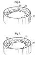
- Fig. 6 shows a partial perspective view of a further embodiment in which the compliant beams or fingers of the spring structure 551 (on the protective structure 55 in the housing 50) are an 'S' shape. This shape allows allows the fingers to be longer than in the embodiment of Fig. 5.
- Fig. 7 shows a partial perspective view of a further embodiment in which the compliant beams of the spring structure 651 are cupped such that when they contact the coiled ceramic actuator (not shown) the load is distributed over a greater area.
- the cups are designed to follow the curvature of the surface of the ceramic actuator.
- the cupped fingers 651 repeat along the length of the protective structure 65 within the housing 60; in the drawing only 3 of the cupped fingers are shown.
- Figs. 1 to 7 are examples of compliant structures and it will be apparent that other variations fall within the scope of the present invention.
- a camera housing 100 for a miniature camera.
- the housing 100 includes a top lid 101 with a central opening or aperture 102 for the passage of light from the exterior into the interior of the housing 100. The opening can be covered by an optical filter.
- the lower section of the housing 100 includes a bottom lid 103 and a base plate 104.
- the base plate carries the image sensor (not shown) which may be a CCD or CMOS device together with other circuits to capture the image and transmit it to other parts of the camera.
- an anchor plate 105 which provides mounting points for a suspension system to be described below.
- Another plate 106 is used to mount the fixed end 111 of a piezoelectric actuator 110.
- the housing 100 may be cast into a block of suitable plastic material.
- the housing 100 acts as a support structure for a lens holder 120 as follows.
- Fig. 9 shows the housing 100 with the top lid 101 removed thus exposing the lens holder (or barrel) 120 with a first upper lens 121 visible.
- the lens holder 120 has a nominally cylindrical shape that is flattened along one side 122 to provide a mounting surface for the suspension 130.
- the lens holder 120 is axially movable relative to the housing 100 to allow focusing.
- the actuator 110 comprises a piezoelectric multi-layer, bender tape, for example of a bimorph construction, extending helically around an axis which is itself curved, as described, for example, in WO-01/47041 or D. H. Pearce et al., Sensors and Actuators A 100 (2002), 281 -286
- the actuator 110 comprises a tape wound helically around a first axis, referred to as the minor axis.
- the helically wound portion is further coiled into a secondary winding of about three quarters of a complete turn.
- the axis of this secondary winding is referred to as the major axis.
- the first winding is known as the primary winding or primary helix.
- the secondary winding is about three-quarters of a complete turn
- the secondary winding could be any curve and could exceed one turn and form a spiral or secondary helix. It is therefore usually referred to as secondary curve.
- the tape is arranged on actuation to bend around the minor axis. Due to the helical curve around the minor axis, such bending is concomitant with twisting of the actuator 110 around the minor axis. Due to the curve around the major axis, such twisting is concomitant with relative displacement of the ends 111, 112 of the actuator 110.
- the lens holder 120 is placed in the center of the actuator 110.
- the moving end 112 of the actuator 110 is attached to the lens holder 120 at a point or area at mid-height of the lens holder 120, i.e., close to its equator. Consequently, actuation of the actuator 110 drives movement of the lens holder 120 relative to the housing 100.
- This type of lens suspension and actuation system is described in greater detail in WO-02/103451.
- the fixed end 111 of the actuator 110 extends into a flat portion which acts as a tab for connecting the actuator 110 to the housing 100.
- This tab has electrical contact pads 113 on the bottom face, soldered onto corresponding contact points on the board 106. Through these contacts external control signals or voltage levels are applied to the electrodes of the actuator 110.
- Fig. 10 is a cross-sectional view of the suspension 130.
- the suspension 130 is a specific form of a four-bar linkage comprising four links pivotally connected together in the shape of a parallelogram as follows.
- the first link is a first attachment member 132 rigidly connected to the housing 101, 103.
- the second link is a second attachment member 134 rigidly connected to the lens holder 120.
- the remaining two links are two link elements 133, 135 which each extend, parallel to each other, between the first and second attachment members 132, 134 and are pivotally connected to the first and second attachment members 132, 134 as follows.
- the links 132-135 are integrally formed from a continuous piece of material.
- each link 132-135 tapers towards the portions which connect each adjacent pair of links 132-135, such that the material is reduced to a thin bridge connecting the two adjacent links 132-135, whilst the middle section of each link 132-135 remains relatively stiff.
- the suspension 130 and its links 132-135 offer small resistance against motion of the lens holder 120 in the desired (vertical) direction but much greater resistance against motion in other directions.
- the links 132-135 and, hence, the portions which connect each adjacent pair of links 132-135 have a width of about 4 mm and the nominal diameter of the lens holder 120 is 9.5 mm, thus effectively preventing a rotational or tilting movement of the barrel.
- Each of the portions which connect each adjacent pair of links 132-135 extends linearly in the direction of its axis of relative rotation along the circumference of the lens holder 120 , thus providing resistance to torsional forces which otherwise could lead to a tilting of the suspended camera.
- the length of the portions which connect each adjacent pair of links 132-135 in the above example is approximately a third to half of the diameter of the lens holder.
- the suspension 100 is preferably made from a single piece of polypropylene.
- suitable plastic materials include polyethylene or polyamide (nylon).
- the bars of the suspension can be made from metals or metal alloys.
- the suspension can be cast or injection molded.
- the lens holder 120 is suspended solely by means of the suspension 130 and the actuator 110.
- the system is free of further potential sources of friction such as guide rails or posts to reduce the potential amount of force the actuator has to provide. It was found that even though the suspension 130 connects to the lens holder 120 exclusively within a sector of less than 90 degrees, and both the actuator 110 and the suspension 130 are linked to the lens holder 120 within a sector of less than 120 degrees, the tilt of the lens holder 120 can be kept within the limits required to generate pictures in VGA or SVGA quality.
- the camera assembly also has protective structures of the same type to those described in Figs. 1 to 3, as shown in Figs. 10 and 11, in particular in the form of compliant polyurethane foam layers 108 glued to inner surfaces of the housing 100 around the actuator 110.
- the layers 108 protect the actuator 110 from a sudden impact force, particularly if the force accelerates the actuator 110 in a direction that is not constrained by the suspension 130. In Figs. 10 and 11, this direction is the vertical direction in the paper plane.
- the distance between the actuator 110 in its inactive state, and the foam layers 108 increases towards the moving end of the actuator, so as not to interfere with the nominal displacement of the actuator during the normal operation of the camera.
Landscapes
- Physics & Mathematics (AREA)
- General Physics & Mathematics (AREA)
- Engineering & Computer Science (AREA)
- Optics & Photonics (AREA)
- Manufacturing & Machinery (AREA)
- Computer Hardware Design (AREA)
- Microelectronics & Electronic Packaging (AREA)
- Power Engineering (AREA)
- Condensed Matter Physics & Semiconductors (AREA)
- General Electrical Machinery Utilizing Piezoelectricity, Electrostriction Or Magnetostriction (AREA)
- Lens Barrels (AREA)
- Blocking Light For Cameras (AREA)
- Studio Devices (AREA)
- Motor Or Generator Frames (AREA)
- Compositions Of Oxide Ceramics (AREA)
- Details Of Connecting Devices For Male And Female Coupling (AREA)
Applications Claiming Priority (7)
| Application Number | Priority Date | Filing Date | Title |
|---|---|---|---|
| GBGB0304467.4A GB0304467D0 (en) | 2003-02-26 | 2003-02-26 | Protective housing for ceramic actuators |
| GB0304467 | 2003-02-26 | ||
| GBGB0315273.3A GB0315273D0 (en) | 2003-07-01 | 2003-07-01 | Lens suspension and actuation apparatus |
| GB0315273 | 2003-07-01 | ||
| GB0321499 | 2003-09-13 | ||
| GB0321499A GB0321499D0 (en) | 2003-09-13 | 2003-09-13 | Protective housing for ceramic actuators |
| PCT/GB2004/000749 WO2004077497A2 (en) | 2003-02-26 | 2004-02-25 | Protective housing for a ceramic actuator |
Publications (2)
| Publication Number | Publication Date |
|---|---|
| EP1597778A2 EP1597778A2 (en) | 2005-11-23 |
| EP1597778B1 true EP1597778B1 (en) | 2006-08-16 |
Family
ID=32931044
Family Applications (1)
| Application Number | Title | Priority Date | Filing Date |
|---|---|---|---|
| EP04714370A Expired - Lifetime EP1597778B1 (en) | 2003-02-26 | 2004-02-25 | Protective housing for a ceramic actuator |
Country Status (8)
| Country | Link |
|---|---|
| US (1) | US7227296B2 (enExample) |
| EP (1) | EP1597778B1 (enExample) |
| JP (1) | JP2006519579A (enExample) |
| KR (1) | KR20050104410A (enExample) |
| AT (1) | ATE336804T1 (enExample) |
| DE (1) | DE602004001977T2 (enExample) |
| TW (1) | TW200507309A (enExample) |
| WO (1) | WO2004077497A2 (enExample) |
Families Citing this family (7)
| Publication number | Priority date | Publication date | Assignee | Title |
|---|---|---|---|---|
| JP2005160028A (ja) * | 2003-10-27 | 2005-06-16 | Nec Tokin Corp | 撓み振動型エキサイタ |
| JP2006116399A (ja) * | 2004-10-20 | 2006-05-11 | Citizen Electronics Co Ltd | 撓み振動型エキサイタ |
| GB2421086A (en) * | 2004-12-08 | 2006-06-14 | 1 Ltd | Suspension system with two non parallel hinged linkages for lens |
| JP2007047288A (ja) * | 2005-08-08 | 2007-02-22 | Sanyo Electric Co Ltd | レンズ駆動装置およびそれを備える撮像装置 |
| US7839058B1 (en) * | 2007-01-29 | 2010-11-23 | Microstrain, Inc. | Wideband vibration energy harvester |
| TWI480661B (zh) * | 2010-10-26 | 2015-04-11 | Hon Hai Prec Ind Co Ltd | 自動對焦裝置 |
| US12382833B2 (en) * | 2022-02-18 | 2025-08-05 | Apple Inc. | Piezoelectric mems valve for an electronic device |
Family Cites Families (15)
| Publication number | Priority date | Publication date | Assignee | Title |
|---|---|---|---|---|
| JPS59185316A (ja) | 1983-04-06 | 1984-10-20 | Minolta Camera Co Ltd | カメラの簡易焦点調節機構 |
| CA1225694A (en) | 1983-12-09 | 1987-08-18 | Nippon Telegraph And Telephone Corporation | Piezoelectric actuator using bimorph element |
| JPH03261908A (ja) | 1990-03-13 | 1991-11-21 | Fujitsu Ltd | 光スイッチ |
| US5068567A (en) | 1990-10-26 | 1991-11-26 | General Electric Company | Apparatus for increasing the recoverable energy of a piezoelectric bender |
| EP0730312B1 (en) | 1995-02-28 | 2003-07-30 | Nec Corporation | Packaged piezoelectric transformer unit |
| US6024340A (en) | 1996-12-04 | 2000-02-15 | Active Control Experts, Inc. | Valve assembly |
| JPH11289112A (ja) | 1998-03-31 | 1999-10-19 | Toko Inc | 圧電トランス |
| EP1240676B1 (en) | 1999-12-21 | 2010-01-20 | Cambridge Mechatronics Limited | Electro-active devices |
| JP4547788B2 (ja) * | 2000-03-15 | 2010-09-22 | セイコーエプソン株式会社 | 圧電振動子のパッケージ構造 |
| JP2002319838A (ja) * | 2001-02-19 | 2002-10-31 | Seiko Epson Corp | 圧電デバイス及びそのパッケージ |
| GB2376795B (en) | 2001-06-20 | 2005-03-09 | 1 Ltd | Electro-mechanical control using an electro-active device |
| GB0115073D0 (en) | 2001-06-20 | 2001-08-15 | 1 Ltd | Camera lens positioning using an electro-active device |
| JP3995918B2 (ja) * | 2001-10-29 | 2007-10-24 | セイコーインスツル株式会社 | 表面実装型圧電振動子 |
| GB0128591D0 (en) | 2001-11-29 | 2002-01-23 | 1 Ltd | Mounting system |
| US6713944B2 (en) * | 2002-01-02 | 2004-03-30 | Omron Corporation | Actuator and method of manufacturing a strain element |
-
2004
- 2004-02-25 AT AT04714370T patent/ATE336804T1/de not_active IP Right Cessation
- 2004-02-25 US US10/545,971 patent/US7227296B2/en not_active Expired - Fee Related
- 2004-02-25 KR KR1020057015966A patent/KR20050104410A/ko not_active Withdrawn
- 2004-02-25 WO PCT/GB2004/000749 patent/WO2004077497A2/en not_active Ceased
- 2004-02-25 EP EP04714370A patent/EP1597778B1/en not_active Expired - Lifetime
- 2004-02-25 JP JP2006502321A patent/JP2006519579A/ja active Pending
- 2004-02-25 DE DE602004001977T patent/DE602004001977T2/de not_active Expired - Fee Related
- 2004-02-26 TW TW093104926A patent/TW200507309A/zh unknown
Also Published As
| Publication number | Publication date |
|---|---|
| DE602004001977T2 (de) | 2007-09-06 |
| ATE336804T1 (de) | 2006-09-15 |
| EP1597778A2 (en) | 2005-11-23 |
| JP2006519579A (ja) | 2006-08-24 |
| US20060192461A1 (en) | 2006-08-31 |
| WO2004077497A3 (en) | 2004-12-09 |
| KR20050104410A (ko) | 2005-11-02 |
| US7227296B2 (en) | 2007-06-05 |
| TW200507309A (en) | 2005-02-16 |
| DE602004001977D1 (de) | 2006-09-28 |
| WO2004077497A2 (en) | 2004-09-10 |
Similar Documents
| Publication | Publication Date | Title |
|---|---|---|
| CN101681085B (zh) | 采用晶片级光学系统的自动聚焦/变焦模块 | |
| CN107077044B (zh) | 相机组件 | |
| EP2074444B1 (en) | Design of compact adjustable lens | |
| JP5329629B2 (ja) | カメラモジュール | |
| EP1597778B1 (en) | Protective housing for a ceramic actuator | |
| KR20160034080A (ko) | 액추에이터 유닛 및 카메라 모듈 | |
| US20080196815A1 (en) | Bonding method for laminated piezoelectric element | |
| US20050140792A1 (en) | Camera with adjustable focus | |
| US20060147190A1 (en) | Camera lens suspension | |
| EP1887409A2 (en) | Variable shape mirror | |
| EP4033748A1 (en) | Sma driver, camera device, and electronic device | |
| CN100444421C (zh) | 陶瓷致动器的保护罩 | |
| CN117099032A (zh) | 变焦镜头和变焦摄像模组 | |
| CN112825542A (zh) | 一种成像模组 | |
| US7633209B2 (en) | Driving device capable of obtaining a stable frequency characteristic | |
| KR20140073238A (ko) | 멤스 소자 및 흔들림 보정 장치 | |
| WO2006061623A1 (en) | Camera lens suspension | |
| JP5151995B2 (ja) | 駆動装置 | |
| CN115086507B (zh) | 可伸缩式摄像模组和电子设备 | |
| CN113131782B (zh) | 一种压电驱动器及其制造方法和成像模组 |
Legal Events
| Date | Code | Title | Description |
|---|---|---|---|
| PUAI | Public reference made under article 153(3) epc to a published international application that has entered the european phase |
Free format text: ORIGINAL CODE: 0009012 |
|
| AK | Designated contracting states |
Kind code of ref document: A2 Designated state(s): AT BE BG CH CY CZ DE DK EE ES FI FR GB GR HU IE IT LI LU MC NL PT RO SE SI SK TR |
|
| AX | Request for extension of the european patent |
Extension state: AL LT LV MK |
|
| 17P | Request for examination filed |
Effective date: 20050906 |
|
| GRAP | Despatch of communication of intention to grant a patent |
Free format text: ORIGINAL CODE: EPIDOSNIGR1 |
|
| DAX | Request for extension of the european patent (deleted) | ||
| GRAS | Grant fee paid |
Free format text: ORIGINAL CODE: EPIDOSNIGR3 |
|
| GRAA | (expected) grant |
Free format text: ORIGINAL CODE: 0009210 |
|
| AK | Designated contracting states |
Kind code of ref document: B1 Designated state(s): AT BE BG CH CY CZ DE DK EE ES FI FR GB GR HU IE IT LI LU MC NL PT RO SE SI SK TR |
|
| PG25 | Lapsed in a contracting state [announced via postgrant information from national office to epo] |
Ref country code: LI Free format text: LAPSE BECAUSE OF FAILURE TO SUBMIT A TRANSLATION OF THE DESCRIPTION OR TO PAY THE FEE WITHIN THE PRESCRIBED TIME-LIMIT Effective date: 20060816 Ref country code: IT Free format text: LAPSE BECAUSE OF FAILURE TO SUBMIT A TRANSLATION OF THE DESCRIPTION OR TO PAY THE FEE WITHIN THE PRESCRIBED TIME-LIMIT;WARNING: LAPSES OF ITALIAN PATENTS WITH EFFECTIVE DATE BEFORE 2007 MAY HAVE OCCURRED AT ANY TIME BEFORE 2007. THE CORRECT EFFECTIVE DATE MAY BE DIFFERENT FROM THE ONE RECORDED. Effective date: 20060816 Ref country code: RO Free format text: LAPSE BECAUSE OF FAILURE TO SUBMIT A TRANSLATION OF THE DESCRIPTION OR TO PAY THE FEE WITHIN THE PRESCRIBED TIME-LIMIT Effective date: 20060816 Ref country code: SK Free format text: LAPSE BECAUSE OF FAILURE TO SUBMIT A TRANSLATION OF THE DESCRIPTION OR TO PAY THE FEE WITHIN THE PRESCRIBED TIME-LIMIT Effective date: 20060816 Ref country code: CZ Free format text: LAPSE BECAUSE OF FAILURE TO SUBMIT A TRANSLATION OF THE DESCRIPTION OR TO PAY THE FEE WITHIN THE PRESCRIBED TIME-LIMIT Effective date: 20060816 Ref country code: SI Free format text: LAPSE BECAUSE OF FAILURE TO SUBMIT A TRANSLATION OF THE DESCRIPTION OR TO PAY THE FEE WITHIN THE PRESCRIBED TIME-LIMIT Effective date: 20060816 Ref country code: CH Free format text: LAPSE BECAUSE OF FAILURE TO SUBMIT A TRANSLATION OF THE DESCRIPTION OR TO PAY THE FEE WITHIN THE PRESCRIBED TIME-LIMIT Effective date: 20060816 Ref country code: BE Free format text: LAPSE BECAUSE OF FAILURE TO SUBMIT A TRANSLATION OF THE DESCRIPTION OR TO PAY THE FEE WITHIN THE PRESCRIBED TIME-LIMIT Effective date: 20060816 Ref country code: FI Free format text: LAPSE BECAUSE OF FAILURE TO SUBMIT A TRANSLATION OF THE DESCRIPTION OR TO PAY THE FEE WITHIN THE PRESCRIBED TIME-LIMIT Effective date: 20060816 Ref country code: AT Free format text: LAPSE BECAUSE OF FAILURE TO SUBMIT A TRANSLATION OF THE DESCRIPTION OR TO PAY THE FEE WITHIN THE PRESCRIBED TIME-LIMIT Effective date: 20060816 Ref country code: NL Free format text: LAPSE BECAUSE OF FAILURE TO SUBMIT A TRANSLATION OF THE DESCRIPTION OR TO PAY THE FEE WITHIN THE PRESCRIBED TIME-LIMIT Effective date: 20060816 |
|
| REG | Reference to a national code |
Ref country code: GB Ref legal event code: FG4D |
|
| REG | Reference to a national code |
Ref country code: CH Ref legal event code: EP |
|
| REG | Reference to a national code |
Ref country code: IE Ref legal event code: FG4D |
|
| REF | Corresponds to: |
Ref document number: 602004001977 Country of ref document: DE Date of ref document: 20060928 Kind code of ref document: P |
|
| PG25 | Lapsed in a contracting state [announced via postgrant information from national office to epo] |
Ref country code: DK Free format text: LAPSE BECAUSE OF FAILURE TO SUBMIT A TRANSLATION OF THE DESCRIPTION OR TO PAY THE FEE WITHIN THE PRESCRIBED TIME-LIMIT Effective date: 20061116 Ref country code: SE Free format text: LAPSE BECAUSE OF FAILURE TO SUBMIT A TRANSLATION OF THE DESCRIPTION OR TO PAY THE FEE WITHIN THE PRESCRIBED TIME-LIMIT Effective date: 20061116 Ref country code: BG Free format text: LAPSE BECAUSE OF FAILURE TO SUBMIT A TRANSLATION OF THE DESCRIPTION OR TO PAY THE FEE WITHIN THE PRESCRIBED TIME-LIMIT Effective date: 20061116 |
|
| PG25 | Lapsed in a contracting state [announced via postgrant information from national office to epo] |
Ref country code: ES Free format text: LAPSE BECAUSE OF FAILURE TO SUBMIT A TRANSLATION OF THE DESCRIPTION OR TO PAY THE FEE WITHIN THE PRESCRIBED TIME-LIMIT Effective date: 20061127 |
|
| PG25 | Lapsed in a contracting state [announced via postgrant information from national office to epo] |
Ref country code: PT Free format text: LAPSE BECAUSE OF FAILURE TO SUBMIT A TRANSLATION OF THE DESCRIPTION OR TO PAY THE FEE WITHIN THE PRESCRIBED TIME-LIMIT Effective date: 20070116 |
|
| NLV1 | Nl: lapsed or annulled due to failure to fulfill the requirements of art. 29p and 29m of the patents act | ||
| PG25 | Lapsed in a contracting state [announced via postgrant information from national office to epo] |
Ref country code: MC Free format text: LAPSE BECAUSE OF NON-PAYMENT OF DUE FEES Effective date: 20070228 |
|
| REG | Reference to a national code |
Ref country code: CH Ref legal event code: PL |
|
| ET | Fr: translation filed | ||
| PLBE | No opposition filed within time limit |
Free format text: ORIGINAL CODE: 0009261 |
|
| STAA | Information on the status of an ep patent application or granted ep patent |
Free format text: STATUS: NO OPPOSITION FILED WITHIN TIME LIMIT |
|
| 26N | No opposition filed |
Effective date: 20070518 |
|
| PG25 | Lapsed in a contracting state [announced via postgrant information from national office to epo] |
Ref country code: IE Free format text: LAPSE BECAUSE OF NON-PAYMENT OF DUE FEES Effective date: 20070226 |
|
| PG25 | Lapsed in a contracting state [announced via postgrant information from national office to epo] |
Ref country code: GR Free format text: LAPSE BECAUSE OF FAILURE TO SUBMIT A TRANSLATION OF THE DESCRIPTION OR TO PAY THE FEE WITHIN THE PRESCRIBED TIME-LIMIT Effective date: 20061117 |
|
| PGFP | Annual fee paid to national office [announced via postgrant information from national office to epo] |
Ref country code: DE Payment date: 20080221 Year of fee payment: 5 |
|
| PG25 | Lapsed in a contracting state [announced via postgrant information from national office to epo] |
Ref country code: EE Free format text: LAPSE BECAUSE OF FAILURE TO SUBMIT A TRANSLATION OF THE DESCRIPTION OR TO PAY THE FEE WITHIN THE PRESCRIBED TIME-LIMIT Effective date: 20060816 |
|
| PGFP | Annual fee paid to national office [announced via postgrant information from national office to epo] |
Ref country code: FR Payment date: 20080208 Year of fee payment: 5 |
|
| PG25 | Lapsed in a contracting state [announced via postgrant information from national office to epo] |
Ref country code: LU Free format text: LAPSE BECAUSE OF NON-PAYMENT OF DUE FEES Effective date: 20070225 Ref country code: CY Free format text: LAPSE BECAUSE OF FAILURE TO SUBMIT A TRANSLATION OF THE DESCRIPTION OR TO PAY THE FEE WITHIN THE PRESCRIBED TIME-LIMIT Effective date: 20060816 |
|
| PG25 | Lapsed in a contracting state [announced via postgrant information from national office to epo] |
Ref country code: HU Free format text: LAPSE BECAUSE OF FAILURE TO SUBMIT A TRANSLATION OF THE DESCRIPTION OR TO PAY THE FEE WITHIN THE PRESCRIBED TIME-LIMIT Effective date: 20070217 Ref country code: TR Free format text: LAPSE BECAUSE OF FAILURE TO SUBMIT A TRANSLATION OF THE DESCRIPTION OR TO PAY THE FEE WITHIN THE PRESCRIBED TIME-LIMIT Effective date: 20060816 |
|
| REG | Reference to a national code |
Ref country code: FR Ref legal event code: ST Effective date: 20091030 |
|
| PG25 | Lapsed in a contracting state [announced via postgrant information from national office to epo] |
Ref country code: DE Free format text: LAPSE BECAUSE OF NON-PAYMENT OF DUE FEES Effective date: 20090901 |
|
| PG25 | Lapsed in a contracting state [announced via postgrant information from national office to epo] |
Ref country code: FR Free format text: LAPSE BECAUSE OF NON-PAYMENT OF DUE FEES Effective date: 20090302 |
|
| PGFP | Annual fee paid to national office [announced via postgrant information from national office to epo] |
Ref country code: GB Payment date: 20160224 Year of fee payment: 13 |
|
| GBPC | Gb: european patent ceased through non-payment of renewal fee |
Effective date: 20170225 |
|
| PG25 | Lapsed in a contracting state [announced via postgrant information from national office to epo] |
Ref country code: GB Free format text: LAPSE BECAUSE OF NON-PAYMENT OF DUE FEES Effective date: 20170225 |