EP1596235B1 - Optical device and a microlithography projection exposure system with passive thermal compensation - Google Patents
Optical device and a microlithography projection exposure system with passive thermal compensation Download PDFInfo
- Publication number
- EP1596235B1 EP1596235B1 EP05106797A EP05106797A EP1596235B1 EP 1596235 B1 EP1596235 B1 EP 1596235B1 EP 05106797 A EP05106797 A EP 05106797A EP 05106797 A EP05106797 A EP 05106797A EP 1596235 B1 EP1596235 B1 EP 1596235B1
- Authority
- EP
- European Patent Office
- Prior art keywords
- projection exposure
- exposure apparatus
- optical element
- microlithographic projection
- lens
- Prior art date
- Legal status (The legal status is an assumption and is not a legal conclusion. Google has not performed a legal analysis and makes no representation as to the accuracy of the status listed.)
- Expired - Lifetime
Links
Images


Classifications
-
- G—PHYSICS
- G03—PHOTOGRAPHY; CINEMATOGRAPHY; ANALOGOUS TECHNIQUES USING WAVES OTHER THAN OPTICAL WAVES; ELECTROGRAPHY; HOLOGRAPHY
- G03F—PHOTOMECHANICAL PRODUCTION OF TEXTURED OR PATTERNED SURFACES, e.g. FOR PRINTING, FOR PROCESSING OF SEMICONDUCTOR DEVICES; MATERIALS THEREFOR; ORIGINALS THEREFOR; APPARATUS SPECIALLY ADAPTED THEREFOR
- G03F7/00—Photomechanical, e.g. photolithographic, production of textured or patterned surfaces, e.g. printing surfaces; Materials therefor, e.g. comprising photoresists; Apparatus specially adapted therefor
- G03F7/70—Microphotolithographic exposure; Apparatus therefor
- G03F7/70216—Mask projection systems
- G03F7/70358—Scanning exposure, i.e. relative movement of patterned beam and workpiece during imaging
-
- G—PHYSICS
- G02—OPTICS
- G02B—OPTICAL ELEMENTS, SYSTEMS OR APPARATUS
- G02B7/00—Mountings, adjusting means, or light-tight connections, for optical elements
- G02B7/02—Mountings, adjusting means, or light-tight connections, for optical elements for lenses
- G02B7/028—Mountings, adjusting means, or light-tight connections, for optical elements for lenses with means for compensating for changes in temperature or for controlling the temperature; thermal stabilisation
-
- G—PHYSICS
- G03—PHOTOGRAPHY; CINEMATOGRAPHY; ANALOGOUS TECHNIQUES USING WAVES OTHER THAN OPTICAL WAVES; ELECTROGRAPHY; HOLOGRAPHY
- G03F—PHOTOMECHANICAL PRODUCTION OF TEXTURED OR PATTERNED SURFACES, e.g. FOR PRINTING, FOR PROCESSING OF SEMICONDUCTOR DEVICES; MATERIALS THEREFOR; ORIGINALS THEREFOR; APPARATUS SPECIALLY ADAPTED THEREFOR
- G03F7/00—Photomechanical, e.g. photolithographic, production of textured or patterned surfaces, e.g. printing surfaces; Materials therefor, e.g. comprising photoresists; Apparatus specially adapted therefor
- G03F7/70—Microphotolithographic exposure; Apparatus therefor
- G03F7/70058—Mask illumination systems
- G03F7/70091—Illumination settings, i.e. intensity distribution in the pupil plane or angular distribution in the field plane; On-axis or off-axis settings, e.g. annular, dipole or quadrupole settings; Partial coherence control, i.e. sigma or numerical aperture [NA]
- G03F7/70108—Off-axis setting using a light-guiding element, e.g. diffractive optical elements [DOEs] or light guides
-
- G—PHYSICS
- G03—PHOTOGRAPHY; CINEMATOGRAPHY; ANALOGOUS TECHNIQUES USING WAVES OTHER THAN OPTICAL WAVES; ELECTROGRAPHY; HOLOGRAPHY
- G03F—PHOTOMECHANICAL PRODUCTION OF TEXTURED OR PATTERNED SURFACES, e.g. FOR PRINTING, FOR PROCESSING OF SEMICONDUCTOR DEVICES; MATERIALS THEREFOR; ORIGINALS THEREFOR; APPARATUS SPECIALLY ADAPTED THEREFOR
- G03F7/00—Photomechanical, e.g. photolithographic, production of textured or patterned surfaces, e.g. printing surfaces; Materials therefor, e.g. comprising photoresists; Apparatus specially adapted therefor
- G03F7/70—Microphotolithographic exposure; Apparatus therefor
- G03F7/70216—Mask projection systems
- G03F7/70241—Optical aspects of refractive lens systems, i.e. comprising only refractive elements
-
- G—PHYSICS
- G03—PHOTOGRAPHY; CINEMATOGRAPHY; ANALOGOUS TECHNIQUES USING WAVES OTHER THAN OPTICAL WAVES; ELECTROGRAPHY; HOLOGRAPHY
- G03F—PHOTOMECHANICAL PRODUCTION OF TEXTURED OR PATTERNED SURFACES, e.g. FOR PRINTING, FOR PROCESSING OF SEMICONDUCTOR DEVICES; MATERIALS THEREFOR; ORIGINALS THEREFOR; APPARATUS SPECIALLY ADAPTED THEREFOR
- G03F7/00—Photomechanical, e.g. photolithographic, production of textured or patterned surfaces, e.g. printing surfaces; Materials therefor, e.g. comprising photoresists; Apparatus specially adapted therefor
- G03F7/70—Microphotolithographic exposure; Apparatus therefor
- G03F7/708—Construction of apparatus, e.g. environment aspects, hygiene aspects or materials
- G03F7/70808—Construction details, e.g. housing, load-lock, seals or windows for passing light in or out of apparatus
- G03F7/70825—Mounting of individual elements, e.g. mounts, holders or supports
-
- G—PHYSICS
- G03—PHOTOGRAPHY; CINEMATOGRAPHY; ANALOGOUS TECHNIQUES USING WAVES OTHER THAN OPTICAL WAVES; ELECTROGRAPHY; HOLOGRAPHY
- G03F—PHOTOMECHANICAL PRODUCTION OF TEXTURED OR PATTERNED SURFACES, e.g. FOR PRINTING, FOR PROCESSING OF SEMICONDUCTOR DEVICES; MATERIALS THEREFOR; ORIGINALS THEREFOR; APPARATUS SPECIALLY ADAPTED THEREFOR
- G03F7/00—Photomechanical, e.g. photolithographic, production of textured or patterned surfaces, e.g. printing surfaces; Materials therefor, e.g. comprising photoresists; Apparatus specially adapted therefor
- G03F7/70—Microphotolithographic exposure; Apparatus therefor
- G03F7/708—Construction of apparatus, e.g. environment aspects, hygiene aspects or materials
- G03F7/70858—Environment aspects, e.g. pressure of beam-path gas, temperature
- G03F7/70883—Environment aspects, e.g. pressure of beam-path gas, temperature of optical system
- G03F7/70891—Temperature
Definitions
- the invention relates to a projection exposure apparatus of microlithography according to the preamble of claim 1, in which a non-rotationally symmetrical thermal influencing of an optical element takes place by the light source.
- This situation has particular significance in wafer scanners with a slit image field - either a narrow rectangle of width-to-length ratio, e.g. from typically 1: 5 to 1: 9, or especially in mirror systems also circular arc.
- EP-B1 0 532 2366 preferably as a heater for mirrors.
- the object of the invention is to significantly reduce or symmetrize the change in the properties of optical elements caused by light absorption and consequent heating with the simplest possible means.
- Active, controlled or regulated interventions on the optical elements are dispensed with. By avoiding active elements and especially a heater, the entire energy input is reduced in the arrangement.
- the invention with the asymmetric cooling of proven, and especially in projection exposure systems hitherto driven to the extreme, construction principles of the versions with high symmetry.
- This departure is e.g. in an optical arrangement with a light source and an optical element attached to a socket, wherein the light source emits radiation and the optical element is acted upon in such a way that a heat supply takes place which has no symmetry corresponding to the shape of the optical element.
- a connecting structure is provided between the optical element and the socket, which has a symmetry which does not correspond to the shape of the optical element and which effects an at least partial homogenization of the temperature distribution in the optical element.
- an optical arrangement with a light source and an optical element which is fastened in a mount, wherein the light source emits radiation and the optical element is acted upon in such a way that a heat supply takes place which does not correspond to the shape of the optical element Has symmetry.
- a one- or multi-part heat-conducting element is arranged in operative connection with the optical element and the socket, so that a form of heat transport takes place, which causes an at least partial compensation of the asymmetry of the temperature distribution in the optical element.
- the projection exposure apparatus comprises an optical element which is not rotationally symmetrically heated by radiation, and wherein at least one part is in thermal contact with the optical element and covers part of the non-irradiated cross section of the optical element to reduce temperature gradients in the optical element.
- Figure 1 shows a lens frame 2, in which a lens 1 by a plurality of webs 21-28 (eight are shown) is kept largely tension-free and exactly fixed in position.
- the webs 21-28 spoke, tabs
- the webs 21-28 are glued to the edge of the lens 1 or connected by other joining methods.
- the lens 1 is illuminated.
- the problem is that the lens materials have considerable absorption and consequently in cross section 10 takes place a considerable heat.
- the associated increase in temperature causes a change in the refractive index and by the thermal expansion in addition to a deformation. Overall, there is a change in the lens effect with astigmatic effect.
- the cooling takes place only to a small extent via the ambient gas (in the case of projection exposure systems, as a rule, helium) and by heat radiation.
- the primary heat is the heat over the lens body 1, the joint (gluing) and the gas in the Environment of the joint and the webs 21-28 discharged to the socket 2.
- the webs 21-28 in this example are made of different materials, with which they have different thermal conductivity.
- the webs 21, 25 closest to the slit-shaped cross-section 10 are of very good thermal conductivity, the most distant lead 23, 27 of low thermal conductivity lead, and the intermediate webs 22, 24, 26, 28 of medium thermal conductivity aluminum.
- the temperature distribution in the lens 1 is thus relatively lowered between the webs 21, 23 and relatively raised between the webs 23, 27, resulting in a - at least partially - homogenization and symmetrization of the temperature distribution and a reduced disturbance of the optical properties of the lens 1.
- lens 1 and socket 2 are connected via webs 211 to 214 (four pieces only for clear presentation, in practice more) with different cross section and thus different heat conduction. Different mechanical properties are prevented by each web 211 to 214 having similar spring joints 221 to 224. The heat conduction through the adjoining narrow gaps (only minimal mobility of the joints are required) takes place sufficiently effectively by the filling gas (helium) or by a flexible metal cable (stranded wire) connected in parallel (see FIG. 6b).
- FIG. 2 Also shown in this Figure 2 is a "dipole" illumination of the lens with two eccentric spots 101, 102 as seen in the area of the aperture plane and equivalent planes of symmetrical slant illumination projection exposure systems. Also, this results in astigmatic errors due to the absorption of light, which can be reduced by the passive compensating cooling.
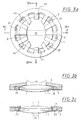
- Figure 3a-c shows a variant of the invention with an additional, provided only for the compensatory cooling, heat-conducting element 3rd
- Lens 1 and 2 socket are connected, for example, with uniform webs or with selectively cooling webs 21-28 of Figure 1 or 2. Any other socket technique is equally applicable.
- the heat-conducting element 3 is firmly connected to the socket 2 with good thermal conductivity and covers parts of the lens 1, which are not penetrated by the light, that is outside of the illuminated area 10 shown here as a slot.
- This overlap preferably occurs without contact, for example at a distance of about 0.1 mm, so that a good heat transfer is ensured by the intermediary of the filling gas, but at the same time no stresses can be introduced into the lens 1.
- Better heat conduction results, of course, when the gap between the lens 1 and thermally conductive element 3 with adhesive, a gel, liquid crystals or the like, as little as possible voltage-transmitting material is filled.
- the heat-conducting element 3 With the embodiment of the heat-conducting element 3 with a plurality of fingers or spokes shown in FIG. 3a, its width, shape and distribution can also be used to adjust the heat conduction. Even when designed as a continuous disc or pinhole, the thickness of the heat-conducting element can be made locally different. It is also possible to make the individual fingers analogous to the webs 21-28 of Figure 1 from different heat-conducting materials. Of course, the heat-conducting element 3 can also be arranged on both sides of the lens 1.
- FIG. 4 shows in a representation corresponding to FIG. 3b a possibility of how the cooling element 3 can be brought into material or positive contact with the lens 1 without the mechanical properties of the socket 2 and the connecting parts 21 being disturbed.
- the cooling element 3 is for this purpose equipped with a flexible thermally conductive cable 30 - e.g. a copper wire - and connected to a heat sink 20.
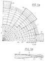
- Figure 5a shows in plan view the finite element model of a quadrant of a lens 1 made of quartz glass (center thickness 14.4 mm, upper radius of curvature 1600 mm, lower radius of curvature 220 mm - biconvex -, diameter 160 mm).
- Eight massive tabs (51, 52, 53) made of aluminum are evenly distributed on the lens 1 in the manner visible from the section 5b. They are 30 mm wide, 2 mm thick above the lens and 6 mm radially overlapping, outside they are again radially 8 mm long in 4 mm thickness. At the outer edge, they are kept at base temperature, e.g. by flexible thermally conductive strands 50.
- cooling straps located on the Y-axis are omitted.
- the lying on the X-axis cooling flaps 510 are doubled in width and also made of the better heat-conducting silver.
- the tabs 52 between them remain unchanged, as well as the heat in the area 4.
- the temperature increase at the center is now 9.2 milligrams.
- the isotherms are now well rotationally symmetric up to about 0.7 times the maximum temperature increase and half the lens diameter.
- the mechanical version of the lens 1 can either be done by the cooling straps 510, 52, or it is provided any socket technology, which preferably has comparatively low heat conduction.
- Figure 7 shows a variant similar to Figure 3a-c, in which the fingers 31, 32 of the thermally conductive element made of bimetal - two layers of material with different thermal expansion - are executed.
- the bimetallic strip 31 On the left in the picture, the bimetallic strip 31 is bent away from the lens 1 at the low temperature t 1 , it can absorb only a small amount of heat.
- the bimetallic strip 32 is stretched and is located at a small distance from the lens 1, so that it can dissipate a lot of heat.
- the invention can also be applied to prismatic parts, to gratings or mirrors, even to all non-uniformly heat-stressed optical components.
- FIG. 8 shows an embodiment specially adapted to a mirror 6.
- the mirror 6 is supported on a holder 7 via supports 71 to 77 distributed on its rear side - individual webs or support rings.
- the different thermal expansion of the materials for the supports 71-77 can also be specifically exploited to compensate for Deformationen.des mirror 6 due to heating, or also bring about targeted. In the latter case, disturbances of other optical elements that interact with the mirror 6 in a system can then be compensated.
- FIG 9 shows the complete optical system of a projection exposure system of microlithography in a schematic overview.
- a DUV excimer laser serves as the light source 61.
- a beam-shaping optics 62 with a zoom axicon objective 63, optionally a diaphragm 64 (exchangeable, conventional, annular aperture, dipole, quadrupole aperture) and a homogenizing quartz rod 65 illuminate the REMA.
- Aperture 66 homogeneous, which is mapped by the following REMA lens 67 as sharply bordered homogeneous spot, especially as a narrow scan slot on the mask 68.
- the following reducing projection lens 69 images the mask 68 on the wafer 70.
- the near-field lenses 671 and 672 of the REMA objective 67 and 692 of the projection lens 69 are now preferred optical elements on which the cooling according to the invention is used. This cooling reduces the aberrations that occur in a scanner in which mask 68 and wafer 70 are synchronously scanned due to the narrow slit-shaped illuminated field.
- the lens 691 is disposed next to the aperture 690 of the projection lens 69. It is controlled by special types of lighting, e.g. Dipole aperture, particularly stressed (see Figure 2). By asymmetric cooling according to the invention, however, this disorder can also be reduced.
Description
Die Erfindung betrifft eine Projektionsbelichtungsanlage der Mikrolithographie nach dem Oberbegriff des Anspruchs 1, bei der eine nicht rotationssymmetrische thermische Beeinflussung eines optischen Elements durch die Lichtquelle erfolgt.The invention relates to a projection exposure apparatus of microlithography according to the preamble of
Diese Situation hat eine besondere Bedeutung bei Wafer-Scannern mit einem schlitzförmigen Bildfeld - entweder ein schmales Rechteck mit Verhältnis Breite zu Länge z.B. von typisch 1:5 bis zu 1:9, oder insbesondere bei Spiegelsystemen auch kreisbogenförmig.This situation has particular significance in wafer scanners with a slit image field - either a narrow rectangle of width-to-length ratio, e.g. from typically 1: 5 to 1: 9, or especially in mirror systems also circular arc.
Eine aktive Kompensation dadurch verursachter Abbildungsfehler ist aus EP-A 0 678 768 bekannt durch geregeltes oder gesteuertes nicht rotationssymmetrisches Heizen oder Kühlen oder andeutungsweise auch durch mechanisches Spannen.Active compensation of imaging errors caused thereby is known from EP-
Schon früher ist derartiges in der EP-B1 0 532 236 beschrieben, vorzugsweise als Heizung für Spiegel.Previously, such is described in EP-
Aufgabe der Erfindung ist es, die durch Lichtabsorption und daraus folgende Erwärmung verursachte Veränderung der Eigenschaften optischer Elemente mit möglichst einfachen Mitteln deutlich zu reduzieren bzw. zu symmetrisieren.The object of the invention is to significantly reduce or symmetrize the change in the properties of optical elements caused by light absorption and consequent heating with the simplest possible means.
Gelöst wird diese Aufgabe durch eine Projektionsbelichtungsanlage nach Anspruch 1.This object is achieved by a projection exposure apparatus according to
Auf aktive, gesteuerte oder geregelte Eingriffe an den optischen Elementen wird verzichtet. Durch die Vermeidung aktiver Elemente und besonders einer Heizung wird der gesamte Energieeintrag in die Anordnung reduziert.Active, controlled or regulated interventions on the optical elements are dispensed with. By avoiding active elements and especially a heater, the entire energy input is reduced in the arrangement.
Andererseits geht die Erfindung mit der asymmetrischen Kühlung von bewährten, und besonders bei Projektionsbelichtungsanlagen bisher auf die Spitze getriebenen, Bauprinzipien der Fassungen mit hoher Symmetrie ab. Dieses Abgehen erfolgt z.B. in einer optischen Anordnung mit einer Lichtquelle und einem an einer Fassung befestigten optischen Element, wobei die Lichtquelle Strahlung emittiert und das optische Element damit derart beaufschlagt, dass eine Wärmezufuhr erfolgt, die keine der Form des optischen Elements entsprechende Symmetrie aufweist. Dabei ist zwischen optischem Element und Fassung eine Verbindungsstruktur vorgesehen, die eine nicht der Form des optischen Elements entsprechende Symmetrie aufweist und eine zumindest teilweise Homogenisierung der Temperaturverteilung im optischen Element bewirkt.On the other hand, the invention with the asymmetric cooling of proven, and especially in projection exposure systems hitherto driven to the extreme, construction principles of the versions with high symmetry. This departure is e.g. in an optical arrangement with a light source and an optical element attached to a socket, wherein the light source emits radiation and the optical element is acted upon in such a way that a heat supply takes place which has no symmetry corresponding to the shape of the optical element. In this case, a connecting structure is provided between the optical element and the socket, which has a symmetry which does not correspond to the shape of the optical element and which effects an at least partial homogenization of the temperature distribution in the optical element.
Alternativ oder zusätzlich kann auch eine optische Anordnung mit einer Lichtquelle und einem optischen Element das in einer Fassung befestigt ist verwendet werden, wobei die Lichtquelle Strahlung emittiert und das optische Element damit derart beaufschlagt, dass eine Wärmezufuhr erfolgt, die keine der Form des optischen Elements entsprechende Symmetrie aufweist. Dabei ist ein ein- oder mehrteiliges wärmeleitendes Element in Wirkverbindung mit dem optischen Element und der Fassung angeordnet, so dass eine Form des Wärmetransports erfolgt, die eine zumindest teilweise Kompensation der Asymmetrie der Temperaturverteilung im optischen Element bewirkt.Alternatively or additionally, it is also possible to use an optical arrangement with a light source and an optical element which is fastened in a mount, wherein the light source emits radiation and the optical element is acted upon in such a way that a heat supply takes place which does not correspond to the shape of the optical element Has symmetry. In this case, a one- or multi-part heat-conducting element is arranged in operative connection with the optical element and the socket, so that a form of heat transport takes place, which causes an at least partial compensation of the asymmetry of the temperature distribution in the optical element.
Bei der letzt genannten Ausführung oder bei einer Projektionsbelichtungsanlage der Mikrolithographie ist eine Kühlung durch Teile ohne Fassungsfunktion vorgesehen, so dass die eigentliche Fassung wieder symmetrisch bleiben kann. Dabei umfasst die Projektionsbelichtungsanlage ein optisches Element, das durch Strahlung nicht rotationssymmetrisch beheizt wird, und wobei mindestens ein Teil in thermischem Kontakt zum optischen Element steht und einen Teil des nicht von der Strahlung berührten Querschnitts des optischen Elements abdeckt, um Temperaturgradienten im optischen Element zu reduzieren.In the latter embodiment or in a projection exposure system of microlithography cooling is provided by parts without socket function, so that the actual version can remain symmetrical again. there The projection exposure apparatus comprises an optical element which is not rotationally symmetrically heated by radiation, and wherein at least one part is in thermal contact with the optical element and covers part of the non-irradiated cross section of the optical element to reduce temperature gradients in the optical element.
Vorteilhafte Weiterbildungen der Erfindung sind Gegenstand der Unteransprüche 2 bis 11.Advantageous developments of the invention are subject of the
Näher erläutert wird die Erfindung anhand der Zeichnungen.
Figur 1- zeigt schematisch eine Linse mit schlitzförmiger Ausleuchtung und Laschenverbindungen der Fassung aus verschiedenen Materialien;
Figur 2- zeigt schematisch eine Linse mit dipolartiger Ausleuchtung und Verbindungen zur Fassung mit unterschiedlichen Querschnitten;
- Figur 3a
- zeigt schematisch eine Linse mit schlitzförmiger Ausleuchtung in symmetrischer Fassung mit einem Kühlkörper von nicht rotationssymmetrischer Form;
- Figur 3b
- zeigt einen Schnitt A-A von Figur 3a;
- Figur 3c
- zeigt einen Schnitt B-B von Figur 3b;
Figur 4- zeigt schematisch im Querschnitt eine Variante mit Kühllasche und Wärmeleitkabel;
- Figur 5a
- gleichen zeigt ein FEM-Modell mit symmetrisch angeordneten Kühlkörpern;
- Figur 5b
- zeigt dazu schematisch einen Querschnitt;
Figur 6- zeigt ein gleichartiges FEM-Modell wie Figur 5a, bei dem die Kühlkörper nach Lage, Größe und Material variiert sind;
Figur 7- zeigt eine Variante mit einem Kühlkörper mit temperaturinduzierter Veränderung der Kühlwirkung;
- Figur 8
- zeigt im schematischen Schnitt einen Spiegel mit durch Stege aus verschiedenen Materialien bewirkter unterschiedlicher Kühlung; und
- Figur 9
- zeigt schematisch die Übersicht einer Projektionsbelichtungsanlage.
- FIG. 1
- shows schematically a lens with slit-shaped illumination and tab connections of the socket made of different materials;
- FIG. 2
- shows schematically a lens with Dipolartiger illumination and connections to the socket with different cross-sections;
- FIG. 3a
- shows schematically a lens with slit-shaped illumination in a symmetrical version with a heat sink of non-rotationally symmetrical shape;
- FIG. 3b
- shows a section AA of Figure 3a;
- Figure 3c
- shows a section BB of Figure 3b;
- FIG. 4
- shows schematically in cross section a variant with cooling plate and heat conduction cable;
- FIG. 5a
- same shows a FEM model with symmetrically arranged heat sinks;
- FIG. 5b
- schematically shows a cross section;
- FIG. 6
- shows a similar FEM model as Figure 5a, in which the heat sinks are varied by location, size and material;
- FIG. 7
- shows a variant with a heat sink with temperature-induced change in the cooling effect;
- FIG. 8
- shows in schematic section a mirror with webs made of different materials verwirkter different cooling; and
- FIG. 9
- schematically shows the overview of a projection exposure system.
Die Anordnung der Figur 1 zeigt eine Linsenfassung 2, in der eine Linse 1 durch eine Vielzahl von Stegen 21-28 (gezeigt sind acht) weitestgehend spannungsfrei und exakt lagefixiert gehalten ist. Die Stege 21-28 (Speichen, Laschen) sind mit dem Rand der Linse 1 verklebt oder durch andere Fügeverfahren verbunden.The arrangement of Figure 1 shows a
In einem schlitzförmigen Querschnitt 10 wird die Linse 1 ausgeleuchtet. Gerade bei Projektionsbelichtungsanlagen, die im UV- und DUV-Bereich arbeiten, ist das Problem, daß die Linsenwerkstoffe erhebliche Absorption aufweisen und in Folge also im Querschnitt 10 eine erhebliche Wärmezufuhr erfolgt. Die damit verbundene Temperaturerhöhung bewirkt eine Änderung des Brechungsindex und durch die Wärmeausdehnung zusätzlich eine Deformation. Insgesamt ergibt sich eine Veränderung der Linsenwirkung mit astigmatischer Wirkung.In a slot-shaped
Die Kühlung erfolgt nur zu einem geringen Teil über das Umgebungsgas (bei Projektionsbelichtungsanlagen in der Regel Helium) und durch Wärmestrahlung. Primär wird die Wärme über den Linsenkörper 1, die Fügestelle (Klebung) und das Gas in der Umgebung der Fügestelle und die Stege 21-28 auf die Fassung 2 abgeführt.The cooling takes place only to a small extent via the ambient gas (in the case of projection exposure systems, as a rule, helium) and by heat radiation. The primary heat is the heat over the
Erfindungsgemäß sind nun die Stege 21-28 in diesem Beispiel aus verschiedenen Materialien ausgeführt, womit sie unterschiedliche Wärmeleitfähigkeit aufweisen. Beispielsweise sind die dem schlitzförmigen Querschnitt 10 nächstgelegenen Stege 21, 25 aus Silber mit sehr guter Wärmeleitfähigkeit, die entferntesten 23, 27 aus Blei mit geringer Wärmeleitfähigkeit und die dazwischenliegenden Stege 22, 24, 26, 28 aus Aluminium mit mittlerer Wärmeleitfähigkeit. Die Temperaturverteilung in der Linse 1 wird also zwischen den Stegen 21, 23 relativ abgesenkt und zwischen den Stegen 23, 27 relativ angehoben, wodurch sich eine - zumindest teilweise - Homogenisierung und Symmetrisierung der Temperaturverteilung und eine reduzierte Störung der optischen Eigenschaften der Linse 1 ergibt.According to the invention, the webs 21-28 in this example are made of different materials, with which they have different thermal conductivity. For example, the
In der Praxis sind auch weitere Eigenschaften der für die Stege 21-28 verwendeten Materialien, wie ihre Festigkeit, Elastizität, Wärmeausdehnung zu berücksichtigen. Simulationsrechnungen für die mechanischen, thermischen und optischen Eigenschaften unter Nutzung der Finite Elemente Methode ermöglichen hier eine optimierte Auswahl und Ausführung der Anordnung.In practice, other properties of the materials used for the webs 21-28, such as their strength, elasticity, thermal expansion must be taken into account. Simulation calculations for the mechanical, thermal and optical properties using the finite element method enable an optimized selection and design of the arrangement.
Eine Alternative, die an sich nicht zur Erfindung gehört aber zur Kombination mit oben genanntem Beispiel eignet, gibt Figur 2 wieder. Hier sind Linse 1 und Fassung 2 über Stege 211 bis 214 (vier Stück nur zur klaren Darstellung, in der Praxis mehr) mit unterschiedlichem Querschnitt und dadurch unterschiedlicher Wärmeleitung verbunden. Unterschiedliche mechanische Eigenschaften sind dadurch unterbunden, daß jeder Steg 211 bis 214 gleichartige Federgelenke 221 bis 224 aufweist. Die Wärmeleitung über die danebenliegenden schmalen Spalte (es werden nur minimale Beweglichkeiten der Gelenke benötigt) erfolgt hinreichend wirksam durch das Füllgas (Helium) oder durch ein parallel geschaltetes flexibles Metallkabel (Litze) (vgl. Fig. 6b).An alternative which does not belong to the invention per se but is suitable for combination with the above-mentioned example, Figure 2 again. Here,
Auch hier wird die genaue Kombination mit Unterstützung von Simulationsrechnungen festgelegt. Die Kombination mit der Verwendung unterschiedlicher Werkstoffe, wie in Figur 1 dargestellt, eröffnet erweiterte Anpassungsmöglichkeiten.Again, the exact combination is determined with the support of simulation calculations. The combination with the use of different materials, as shown in Figure 1, opens up extended customization options.
Weiter ist in dieser Figur 2 eine "Dipol"-Ausleuchtung der Linse mit zwei außermittigen Lichtflecken 101, 102 dargestellt, wie sie im Bereich der Blendenebene und äquivalenter Ebenen von Projektionsbelichtungssystemen mit symmetrischer schiefer Beleuchtung vorkommt. Auch damit ergeben sich astigmatische Fehler durch die Lichtabsorption, die durch die passivkompensierende Kühlung vermindert werden können.Also shown in this Figure 2 is a "dipole" illumination of the lens with two
Figur 3a-c zeigt eine Variante der Erfindung mit einem zusätzlichen, nur für die ausgleichende Kühlung vorgesehenen, wärmeleitenden Element 3.Figure 3a-c shows a variant of the invention with an additional, provided only for the compensatory cooling, heat-conducting element 3rd
Linse 1 und Fassung 2 sind dabei beispielsweise mit gleichmäßigen Stegen oder mit selektiv kühlenden Stegen 21-28 nach Figur 1 oder 2 verbunden. Jede andere Fassungstechnik ist gleichermaßen.anwendbar.
Das wärmeleitende Element 3 ist mit der Fassung 2 gut wärmeleitend fest verbunden und überdeckt Teile der Linse 1, welche nicht vom Licht durchdrungen werden, also außerhalb der auch hier als Schlitz dargestellten ausgeleuchteten Fläche 10.The heat-conducting
Diese Überdeckung erfolgt vorzugsweise berührungsfrei, etwa mit einem Abstand von rund 0,1 mm, so daß unter Vermittlung des Füllgases eine gute Wärmeübertragung gewährleistet ist, zugleich aber keine Spannungen in die Linse 1 eingetragen werden können. Bessere Wärmeleitung ergibt sich natürlich, wenn der Spalt zwischen Linse 1 und wärmeleitendem Element 3 mit Kleber, einem Gel, Flüssigkristallen oder ähnlichem, möglichst wenig Spannung übertragendem Material, ausgefüllt wird.This overlap preferably occurs without contact, for example at a distance of about 0.1 mm, so that a good heat transfer is ensured by the intermediary of the filling gas, but at the same time no stresses can be introduced into the
Die Wärmeleitung und deren lokale Verteilung wird durch die Form des wärmeleitenden Teils 3 eingestellt - Figur 3b zeigt, wie das Teil 3 bis nahe an den ausgeleuchteten Bereich 10 in der Richtung A-A der Länge des Schlitzes reicht, und Figur 3c zeigt, daß in der Querrichtung B-B der Abstand groß gehalten ist.The heat conduction and its local distribution is set by the shape of the heat-conducting part 3 - Figure 3b shows how the
Mit der in Figur 3a gezeigten Ausführung des wärmeleitenden Elements 3 mit einer Mehrzahl von Fingern oder Speichen kann auch deren Breite, Form und Verteilung zur Einstellung der Wärmeleitung herangezogen werden. Auch bei Ausführung als durchgehende Scheibe bzw. Lochblende kann die Dicke des wärmeleitenden Elements örtlich verschieden ausgeführt werden. Auch ist es möglich, die einzelnen Finger analog zu den Stegen 21-28 nach Figur 1 aus verschieden wärmeleitenden Materialien zu machen. Natürlich kann das wärmeleitende Element 3 auch beidseitig an der Linse 1 angeordnet werden.With the embodiment of the heat-conducting
Fig. 4 zeigt in einer Fig. 3b entsprechenden Darstellung eine Möglichkeit, wie das Kühlelement 3 in stoff- oder formschlüssigen Kontakt zur Linse 1 gebracht werden kann, ohne daß die mechanischen Eigenschaften der Fassung 2 und der Verbindungsteile 21 gestört werden. Das Kühlelement 3 wird dazu mit einem flexiblen wärmeleitenden Kabel 30 ausgestattet - z.B. einer Kupferlitze - und an eine Wärmesenke 20 angeschlossen.FIG. 4 shows in a representation corresponding to FIG. 3b a possibility of how the
Figur 5a zeigt in Aufsicht das Finite-Elemente-Modell eines Quadranten einer Linse 1 aus Quarzglas (Mittendicke 14,4 mm, oberer Krümmungsradius 1600 mm, unterer Krümmungsradius 220 mm - bikonvex -, Durchmesser 160 mm). Acht massive Laschen (51, 52, 53) aus Aluminium sind gleichmäßig verteilt in der aus dem Schnitt Figur 5b erkennbaren Weise an der Linse 1 angeordnet. Sie sind 30 mm breit, über der Linse 2 mm dick und radial 6 mm überdeckend, außerhalb sind sie nochmals radial 8 mm lang in 4 mm Dicke. Am Außenrand sind sie auf Basistemperatur gehalten, z.B. durch flexible wärmeleitende Litzen 50.Figure 5a shows in plan view the finite element model of a quadrant of a
Auf der gezeigten Oberfläche der Linse 1 wird in dem Bereich 4, der etwa ein Rechteck annähert in der gewählten Elementaufteilung, wird eine Wärmeeintragung durch Lichtabsorption von 1 W/cm2 angesetzt. Die Temperaturerhöhung im Mittelpunkt erreicht dann 7,6 Milligrad. Eingezeichnet sind die Isothermen 0,1 bis 0,9, welche den Verlauf der Linien mit dem entsprechenden Bruchteil dieser Temperaturerhöhung anzeigen. Bei höherem Wärmeeintrag skaliert die Temperaturerhöhung in weiten Bereichen linear.On the shown surface of the
Ganz offensichtlich ist bei dieser dem Stand der Technik zuzurechnenden Ausführung mit symmetrischer Kühlanordnung die erreichte Temperaturverteilung stark unsymmetrisch über die ganze Linse verteilt.Obviously, in this state-of-the-art design with symmetrical cooling arrangement, the temperature distribution achieved is distributed very asymmetrically over the entire lens.
Bei der erfindungsgemäßen Ausführung, die in Figur 6 dargestellt ist, sind die auf der Y-Achse liegenden Kühllaschen entfallen. Die auf der X-Achse liegenden Kühllaschen 510 sind in der Breite verdoppelt und zusätzlich aus dem besser wärmeleitenden Silber gefertigt. Die Laschen 52 dazwischen bleiben unverändert, ebenso wie die Wärmezufuhr im Bereich 4.In the embodiment according to the invention, which is shown in FIG. 6, the cooling straps located on the Y-axis are omitted. The lying on the X-axis cooling flaps 510 are doubled in width and also made of the better heat-conducting silver. The
Damit wird nun die Temperaturerhöhung am Mittelpunkt 9,2 Milligrad. Die Isothermen sind bis etwa zum 0,7-fachen der maximalen Temperaturerhöhung und zum halben Linsendurchmesser jetzt gut rotationssymmetrisch.Thus, the temperature increase at the center is now 9.2 milligrams. The isotherms are now well rotationally symmetric up to about 0.7 times the maximum temperature increase and half the lens diameter.
Die mechanische Fassung der Linse 1 kann entweder durch die Kühllaschen 510, 52 erfolgen, oder es ist eine beliebige Fassungstechnik vorgesehen, die vorzugsweise vergleichsweise geringe Wärmeleitung aufweist.The mechanical version of the
Figur 7 zeigt eine Variante ähnlich Figur 3a-c, bei der die Finger 31, 32 des wärmeleitenden Elements aus Bimetall - zwei Lagen Material mit verschiedener Wärmeausdehnung - ausgeführt sind. Links im Bild ist bei der niedrigen Temperatur t1 der Bimetallstreifen 31 von der Linse 1 weggebogen, er kann nur wenig Wärme aufnehmen. Rechts im Bild bei der höheren Temperatur t2 ist der Bimetallstreifen 32 gestreckt und liegt in geringem Abstand zur Linse 1, so daß er viel Wärme abführen kann.Figure 7 shows a variant similar to Figure 3a-c, in which the
Außer bei den in den vorangegangenen Beispielen gezeigten Linsen kann die Erfindung natürlich auch bei prismatischen Teilen, bei Gittern oder Spiegeln angewendet werden, eben allen ungleichmäßig wärmebelasteten optischen Bauteilen.Of course, except in the case of the lenses shown in the preceding examples, the invention can also be applied to prismatic parts, to gratings or mirrors, even to all non-uniformly heat-stressed optical components.
Figur 8 zeigt eine speziell auf einen Spiegel 6 adaptierte Ausführung. Der Spiegel 6 ist auf einer Halterung 7 über auf seiner Rückseite verteilte Stützen 71 bis 77 - einzelne Stege oder Stützringe - abgestützt.FIG. 8 shows an embodiment specially adapted to a
Über ihre Verteilung auf der Rückseite des Spiegels 6, ihre Form sowie über die spezifische Wärmeleitfähigkeit ihres Materials (z.B. in der Mitte 74 aus Silber, am Rand 72, 76 aus Blei, sonst (73, 75) Aluminium und der Außenrand 71, 77 aus Zerodur) wird die Kühlwirkung nach Bedarf eingestellt, in Anpassung an die ausgeleuchtete Fläche 10.About their distribution on the back of the
Die unterschiedliche Wärmeausdehnung der Materialien für die Stützen 71-77 kann ebenfalls gezielt ausgenutzt werden, um Deformationen.des Spiegels 6 aufgrund der Erwärmung zu kompensieren, oder aber auch gezielt herbeizuführen. Im letzteren Fall können dann Störungen anderer optischer Elemente, die in einem System mit dem Spiegel 6 zusammenwirken, kompensiert werden.The different thermal expansion of the materials for the supports 71-77 can also be specifically exploited to compensate for Deformationen.des
Figur 9 zeigt das komplette optische System einer Projektionsbelichtungsanlage der Mikrolithographie im schematisierten Überblick. Ein DUV-Excimer-Laser dient als Lichtquelle 61. Eine strahlformende Optik 62 mit Zoom-Axicon-Objektiv 63, wahlweise einer Blende 64 (wechselbar, konventionelle, Ringapertur, Dipol-, Quadrupol-Apertur) und einem homogenisierenden Quarzstab 65 leuchtet die REMA-Blende 66 homogen aus, die durch das folgende REMA-Objektiv 67 als scharf berandeter homogener Leuchtfleck, insbesondere als schmaler Scan-Schlitz, auf die Maske 68 abgebildet wird.Figure 9 shows the complete optical system of a projection exposure system of microlithography in a schematic overview. A DUV excimer laser serves as the
Das folgende verkleinernde Projektionsobjektiv 69 bildet die Maske 68 auf dem Wafer 70 ab. Die feldnahen Linsen 671 und 672 des REMA-Objektivs 67 und 692 des Projektionsobjektivs 69 sind nun bevorzugte optische Elemente, an denen die erfindungsgemäße Kühlung eingesetzt wird. Diese Kühlung reduziert die bei einem Scanner, bei dem Maske 68 und Wafer 70 synchron gescannt werden, aufgrund des schmalen schlitzförmigen ausgeleuchteten Feldes entstehenden Abbildungsfehler.The following reducing
Die Linse 691 ist nächst der Aperturblende 690 des Projektionsobjektivs 69 angeordnet. Sie wird durch besondere Beleuchtungsarten, z.B. Dipol-Apertur, besonders belastet (vgl. Figur 2). Durch die erfindungsgemäße asymmetrische Kühlung kann jedoch auch diese Störung reduziert werden.The
Es ist klar, daß die Beschreibung der Figuren nur Beispiele für die in den Ansprüchen definierte Erfindung wiedergibt. Insbesondere sind vielfältige Kombinationen der beschriebenen Merkmale erfindungsgemäß möglich und die Kühlung kann auch verstellbar ausgeführt werden, um zu justieren, an Veränderungen.anzupassen usw..It is to be understood that the description of the figures represents only examples of the invention defined in the claims. In particular, various combinations of the described features according to the invention are possible and the cooling can also be made adjustable to adjust, adapt to changes, etc.
Claims (10)
- Microlithographic projection exposure apparatus, having a light source and an optical element (1) which is heated non-axisymmetrically by radiation from the light source, and non-axisymmetric cooling (21-28, 211-214, 3) of the optical element (1), the cooling being carried out by passive thermally conductive devices (21-28, 211-214, 3), characterized in that the passive thermally conductive devices (211-214, 3) consist of struts (21-28) of different materials so as to bring about at least partial homogenization of the temperature distribution in the optical element.
- Microlithographic projection exposure apparatus according to Claim 1, characterized in that the struts (21-28, 211-214) are provided with different cross sections.
- Microlithographic projection exposure apparatus according to Claim 1 or 2, characterized in that the struts (21-28, 211-214) comprise resilient articulations (221-224) of the same type.
- Microlithographic projection exposure apparatus according to one of Claims 1 to 3, characterized in that the passive thermally conductive devices (211-214, 3) comprise fingers of different material, different width, shape or thickness.
- Microlithographic projection exposure apparatus according to one of Claims 1 to 4, characterized in that at least one part (3) is in thermal contact with the optical element (1), covers a part of that cross section of the optical element (1) which is not touched by the radiation, and reduces temperature gradients in the optical element (1).
- Microlithographic projection exposure apparatus according to one of Claims 1 to 5, characterized in that the optical element (1) is a mirror (6) or a transmissive element, in particular a lens (1).
- Microlithographic projection exposure apparatus according to one of Claims 1 to 6, characterized in that the image field (10) is slit-shaped.
- Microlithographic projection exposure apparatus according to one of Claims 1 to 7, characterized in that the optical element (671, 672, 692) is arranged near a field plane or near a pupil plane (690).
- Microlithographic projection exposure apparatus according to Claim 5, characterized in that the part or parts (3, 31, 32) which are in thermal contact consist of a plurality of different materials.
- Projection exposure apparatus according to Claim 5, characterized in that the part or parts (31, 32) which are in thermal contact are at least partially adjustable.
Applications Claiming Priority (3)
| Application Number | Priority Date | Filing Date | Title |
|---|---|---|---|
| DE19807094A DE19807094A1 (en) | 1998-02-20 | 1998-02-20 | Optical arrangement and projection exposure system of microlithography with passive thermal compensation |
| DE19807094 | 1998-02-20 | ||
| EP99100845A EP0938009B1 (en) | 1998-02-20 | 1999-01-19 | Optical device and a microlithography projection exposure system with passive thermal compensation |
Related Parent Applications (1)
| Application Number | Title | Priority Date | Filing Date |
|---|---|---|---|
| EP99100845A Division EP0938009B1 (en) | 1998-02-20 | 1999-01-19 | Optical device and a microlithography projection exposure system with passive thermal compensation |
Publications (2)
| Publication Number | Publication Date |
|---|---|
| EP1596235A1 EP1596235A1 (en) | 2005-11-16 |
| EP1596235B1 true EP1596235B1 (en) | 2007-02-28 |
Family
ID=7858359
Family Applications (2)
| Application Number | Title | Priority Date | Filing Date |
|---|---|---|---|
| EP99100845A Expired - Lifetime EP0938009B1 (en) | 1998-02-20 | 1999-01-19 | Optical device and a microlithography projection exposure system with passive thermal compensation |
| EP05106797A Expired - Lifetime EP1596235B1 (en) | 1998-02-20 | 1999-01-19 | Optical device and a microlithography projection exposure system with passive thermal compensation |
Family Applications Before (1)
| Application Number | Title | Priority Date | Filing Date |
|---|---|---|---|
| EP99100845A Expired - Lifetime EP0938009B1 (en) | 1998-02-20 | 1999-01-19 | Optical device and a microlithography projection exposure system with passive thermal compensation |
Country Status (5)
| Country | Link |
|---|---|
| EP (2) | EP0938009B1 (en) |
| JP (1) | JPH11287936A (en) |
| KR (1) | KR100593429B1 (en) |
| DE (3) | DE19807094A1 (en) |
| TW (1) | TW401516B (en) |
Families Citing this family (23)
| Publication number | Priority date | Publication date | Assignee | Title |
|---|---|---|---|---|
| US7274430B2 (en) | 1998-02-20 | 2007-09-25 | Carl Zeiss Smt Ag | Optical arrangement and projection exposure system for microlithography with passive thermal compensation |
| DE19956353C1 (en) * | 1999-11-24 | 2001-08-09 | Zeiss Carl | Optical arrangement |
| DE19959741A1 (en) * | 1999-12-10 | 2001-06-13 | Zeiss Carl | Device for low-deformation storage of an optical element and method for low-deformation storage of the optical element |
| DE19963588C2 (en) | 1999-12-29 | 2002-01-10 | Zeiss Carl | Optical arrangement |
| US6621557B2 (en) | 2000-01-13 | 2003-09-16 | Nikon Corporation | Projection exposure apparatus and exposure methods |
| DE10151919B4 (en) | 2001-10-20 | 2007-02-01 | Carl Zeiss Smt Ag | Exposure lens in semiconductor lithography |
| EP1310829B1 (en) * | 2001-11-07 | 2007-05-02 | ASML Netherlands B.V. | Lithographic apparatus and device manufacturing method |
| JP2003218023A (en) * | 2002-01-28 | 2003-07-31 | Nikon Corp | X-ray reflecting mirror, x-ray exposure transfer apparatus, and method of manufacturing semiconductor device |
| DE10210893A1 (en) * | 2002-03-07 | 2003-09-18 | Zeiss Carl Laser Optics Gmbh | Optical arrangement has optical component with optically active first region on optical axis of optical system at least partly enclosed by inactive region connected to heat conductive element |
| JP4590205B2 (en) * | 2003-05-14 | 2010-12-01 | キヤノン株式会社 | Mirror holding method, optical apparatus, exposure apparatus, and device manufacturing method |
| GB0511692D0 (en) | 2005-06-08 | 2005-07-13 | Digital Projection Ltd | Heat transfer apparatus |
| DE102006021797A1 (en) * | 2006-05-09 | 2007-11-15 | Carl Zeiss Smt Ag | Optical imaging device with thermal damping |
| GB2451684A (en) * | 2007-08-09 | 2009-02-11 | Digital Projection Ltd | Heat transfer apparatus for cooling a light valve or digital micro mirror |
| WO2009124590A1 (en) * | 2008-04-09 | 2009-10-15 | Carl Zeiss Smt Ag | Optical aperture device |
| DE102009035788B4 (en) * | 2009-07-31 | 2011-06-30 | Carl Zeiss Laser Optics GmbH, 73447 | Optical arrangement in an optical system, in particular a lighting device |
| DE102013203032A1 (en) * | 2013-02-25 | 2014-02-27 | Carl Zeiss Smt Gmbh | Optical arrangement for projection exposure system for semiconductor lithography, has fastening elements for fixing lens in frames, and thermally conductive pastes, bond wires, and thermally conductive rod discharging heat from lens |
| CN103499865B (en) * | 2013-10-10 | 2015-07-29 | 中国科学院上海技术物理研究所 | A kind of optical filter mounting bracket with thermal stress buffer structure |
| DE102015115929B3 (en) | 2015-09-21 | 2016-10-06 | Jenoptik Optical Systems Gmbh | Monolithic lens frame |
| DE102015115931B3 (en) * | 2015-09-21 | 2016-10-27 | Jenoptik Optical Systems Gmbh | Voltage decoupled monolithic lens frame |
| DE102017217111A1 (en) * | 2017-09-26 | 2019-03-28 | Robert Bosch Gmbh | Arrangement of an optical system and cooling methods |
| DE102017217107A1 (en) * | 2017-09-26 | 2019-03-28 | Robert Bosch Gmbh | Arrangement of an optical system and cooling methods |
| WO2019086198A1 (en) | 2017-10-30 | 2019-05-09 | Asml Holding N.V. | Assembly for use in semiconductor photolithography and method of manufacturing same |
| JP6951498B2 (en) * | 2019-06-25 | 2021-10-20 | キヤノン株式会社 | Exposure equipment, exposure method and article manufacturing method |
Family Cites Families (11)
| Publication number | Priority date | Publication date | Assignee | Title |
|---|---|---|---|---|
| US4057332A (en) * | 1976-04-21 | 1977-11-08 | Caterpillar Tractor Co. | Peripherally cooled laser lens assembly |
| US4155631A (en) * | 1977-04-14 | 1979-05-22 | W. J. Schafer Associates, Inc. | Apparatus for compensating for thermally introduced distortions in reflecting surfaces |
| JPS56102392A (en) * | 1980-01-22 | 1981-08-15 | Nec Corp | Laser working optical device |
| JPS6037632B2 (en) * | 1983-02-15 | 1985-08-27 | 株式会社東芝 | Solid state laser oscillator |
| JPS59175178A (en) * | 1983-03-24 | 1984-10-03 | Mitsubishi Electric Corp | Laser device |
| JPS61208002A (en) * | 1985-03-13 | 1986-09-16 | Toshiba Corp | Light transmission device |
| DE69220868T2 (en) | 1991-09-07 | 1997-11-06 | Canon Kk | System for stabilizing the shapes of optical elements, exposure device using this system and method for manufacturing semiconductor devices |
| JPH05203884A (en) * | 1992-01-24 | 1993-08-13 | Toshiba Corp | Optical element |
| JP3169267B2 (en) * | 1992-06-17 | 2001-05-21 | パイオニア株式会社 | Liquid prism |
| JP3368091B2 (en) | 1994-04-22 | 2003-01-20 | キヤノン株式会社 | Projection exposure apparatus and device manufacturing method |
| US5881088A (en) * | 1997-01-08 | 1999-03-09 | Trw Inc. | Face-cooled high-power laser optic cell |
-
1998
- 1998-02-20 DE DE19807094A patent/DE19807094A1/en not_active Withdrawn
- 1998-12-22 KR KR1019980057360A patent/KR100593429B1/en not_active IP Right Cessation
-
1999
- 1999-01-11 TW TW088100316A patent/TW401516B/en not_active IP Right Cessation
- 1999-01-19 DE DE59912313T patent/DE59912313D1/en not_active Expired - Fee Related
- 1999-01-19 EP EP99100845A patent/EP0938009B1/en not_active Expired - Lifetime
- 1999-01-19 EP EP05106797A patent/EP1596235B1/en not_active Expired - Lifetime
- 1999-01-19 DE DE59914228T patent/DE59914228D1/en not_active Expired - Fee Related
- 1999-02-15 JP JP11035932A patent/JPH11287936A/en active Pending
Also Published As
| Publication number | Publication date |
|---|---|
| TW401516B (en) | 2000-08-11 |
| EP0938009A1 (en) | 1999-08-25 |
| EP0938009B1 (en) | 2005-07-27 |
| DE59914228D1 (en) | 2007-04-12 |
| DE59912313D1 (en) | 2005-09-01 |
| KR19990071443A (en) | 1999-09-27 |
| JPH11287936A (en) | 1999-10-19 |
| EP1596235A1 (en) | 2005-11-16 |
| KR100593429B1 (en) | 2006-10-24 |
| DE19807094A1 (en) | 1999-08-26 |
Similar Documents
| Publication | Publication Date | Title |
|---|---|---|
| EP1596235B1 (en) | Optical device and a microlithography projection exposure system with passive thermal compensation | |
| DE19963588C2 (en) | Optical arrangement | |
| DE10000191B4 (en) | Project exposure system for microlithography | |
| DE19963587B4 (en) | Projection exposure system | |
| EP0783137B1 (en) | REMA objective for microlithographic projection illumination | |
| DE19956353C1 (en) | Optical arrangement | |
| DE60210010T2 (en) | Collimation system for laser diode | |
| US20080212052A1 (en) | Optical arrangement and projection exposure system for microlithography with passive thermal compensation | |
| DE102006034755A1 (en) | Optical device and method for correcting or improving the imaging behavior of an optical device | |
| DE19757074A1 (en) | Projection exposure system and exposure method | |
| EP2100190A1 (en) | Illuminating optical unit and projection exposure apparatus for microlithography | |
| DE10140208A1 (en) | Optical arrangement | |
| DE102012223034A1 (en) | Illumination system for extreme UV-projection exposure system used for projecting reflecting structures arranged on lower side in mask on photo resist, has solid body joint including three joint legs, which bend during deflecting rod | |
| DE102009033818A1 (en) | Temperature control device for an optical assembly | |
| WO2009052819A9 (en) | Adaptable optical system | |
| WO1997025722A2 (en) | Condenser-monochromator arrangement for x-radiation | |
| DE102007039019A1 (en) | Device for pivoting an optical beam | |
| DE102004014766A1 (en) | Correcting method for adjusting distortion in an extra-axial field area on a projecting lens' image plane scans a pattern in a reticle onto a carrier for a light-sensitive coating | |
| DE102007061194A1 (en) | Illumination system for extreme ultraviolet micro lithograph, has illumination optic for guiding illuminating light of radiation source into object field in object plane | |
| DE10040998A1 (en) | Projection exposure system | |
| WO2021160583A1 (en) | Projection exposure apparatus with a thermal manipulator | |
| DE102021201412A1 (en) | Tilting device and projection exposure system | |
| WO2004092843A2 (en) | Projection lens, microlithographic projection exposure system and method for producing a semiconductor circuit | |
| DE102011104543A1 (en) | Illuminating system for extreme UV projection exposure system for transferring structures on photoresist, has control device controlling heating device such that quantity of heat supplied to carrier body is spatially and temporally variable | |
| DE102008000968A1 (en) | Optical correction element and method for correcting temperature-induced aberrations in optical systems, projection objective and projection exposure apparatus for semiconductor lithography |
Legal Events
| Date | Code | Title | Description |
|---|---|---|---|
| PUAI | Public reference made under article 153(3) epc to a published international application that has entered the european phase |
Free format text: ORIGINAL CODE: 0009012 |
|
| AC | Divisional application: reference to earlier application |
Ref document number: 0938009 Country of ref document: EP Kind code of ref document: P |
|
| AK | Designated contracting states |
Kind code of ref document: A1 Designated state(s): DE FR GB IE IT NL |
|
| AX | Request for extension of the european patent |
Extension state: AL BA HR MK YU |
|
| AKX | Designation fees paid | ||
| 17P | Request for examination filed |
Effective date: 20060706 |
|
| RBV | Designated contracting states (corrected) |
Designated state(s): DE FR IT NL |
|
| GRAP | Despatch of communication of intention to grant a patent |
Free format text: ORIGINAL CODE: EPIDOSNIGR1 |
|
| GRAS | Grant fee paid |
Free format text: ORIGINAL CODE: EPIDOSNIGR3 |
|
| GRAA | (expected) grant |
Free format text: ORIGINAL CODE: 0009210 |
|
| RAP1 | Party data changed (applicant data changed or rights of an application transferred) |
Owner name: CARL ZEISS SMT AG |
|
| AC | Divisional application: reference to earlier application |
Ref document number: 0938009 Country of ref document: EP Kind code of ref document: P |
|
| AK | Designated contracting states |
Kind code of ref document: B1 Designated state(s): DE FR IT NL |
|
| REF | Corresponds to: |
Ref document number: 59914228 Country of ref document: DE Date of ref document: 20070412 Kind code of ref document: P |
|
| EN | Fr: translation not filed | ||
| PLBE | No opposition filed within time limit |
Free format text: ORIGINAL CODE: 0009261 |
|
| STAA | Information on the status of an ep patent application or granted ep patent |
Free format text: STATUS: NO OPPOSITION FILED WITHIN TIME LIMIT |
|
| 26N | No opposition filed |
Effective date: 20071129 |
|
| PG25 | Lapsed in a contracting state [announced via postgrant information from national office to epo] |
Ref country code: FR Free format text: LAPSE BECAUSE OF FAILURE TO SUBMIT A TRANSLATION OF THE DESCRIPTION OR TO PAY THE FEE WITHIN THE PRESCRIBED TIME-LIMIT Effective date: 20071019 |
|
| PG25 | Lapsed in a contracting state [announced via postgrant information from national office to epo] |
Ref country code: FR Free format text: LAPSE BECAUSE OF FAILURE TO SUBMIT A TRANSLATION OF THE DESCRIPTION OR TO PAY THE FEE WITHIN THE PRESCRIBED TIME-LIMIT Effective date: 20070228 |
|
| PGFP | Annual fee paid to national office [announced via postgrant information from national office to epo] |
Ref country code: DE Payment date: 20090122 Year of fee payment: 11 |
|
| PG25 | Lapsed in a contracting state [announced via postgrant information from national office to epo] |
Ref country code: DE Free format text: LAPSE BECAUSE OF NON-PAYMENT OF DUE FEES Effective date: 20100803 |
|
| PGFP | Annual fee paid to national office [announced via postgrant information from national office to epo] |
Ref country code: NL Payment date: 20150129 Year of fee payment: 17 |
|
| PGFP | Annual fee paid to national office [announced via postgrant information from national office to epo] |
Ref country code: IT Payment date: 20150126 Year of fee payment: 17 |
|
| REG | Reference to a national code |
Ref country code: NL Ref legal event code: MM Effective date: 20160201 |
|
| PG25 | Lapsed in a contracting state [announced via postgrant information from national office to epo] |
Ref country code: NL Free format text: LAPSE BECAUSE OF NON-PAYMENT OF DUE FEES Effective date: 20160201 |
|
| PG25 | Lapsed in a contracting state [announced via postgrant information from national office to epo] |
Ref country code: IT Free format text: LAPSE BECAUSE OF NON-PAYMENT OF DUE FEES Effective date: 20160119 |