EP1596059B1 - Kraftstoffeinspritzventil - Google Patents
Kraftstoffeinspritzventil Download PDFInfo
- Publication number
- EP1596059B1 EP1596059B1 EP03815731.9A EP03815731A EP1596059B1 EP 1596059 B1 EP1596059 B1 EP 1596059B1 EP 03815731 A EP03815731 A EP 03815731A EP 1596059 B1 EP1596059 B1 EP 1596059B1
- Authority
- EP
- European Patent Office
- Prior art keywords
- flow path
- conical
- fuel
- valve
- injection port
- Prior art date
- Legal status (The legal status is an assumption and is not a legal conclusion. Google has not performed a legal analysis and makes no representation as to the accuracy of the status listed.)
- Expired - Lifetime
Links
Images


Classifications
-
- F—MECHANICAL ENGINEERING; LIGHTING; HEATING; WEAPONS; BLASTING
- F02—COMBUSTION ENGINES; HOT-GAS OR COMBUSTION-PRODUCT ENGINE PLANTS
- F02M—SUPPLYING COMBUSTION ENGINES IN GENERAL WITH COMBUSTIBLE MIXTURES OR CONSTITUENTS THEREOF
- F02M51/00—Fuel-injection apparatus characterised by being operated electrically
- F02M51/06—Injectors peculiar thereto with means directly operating the valve needle
- F02M51/061—Injectors peculiar thereto with means directly operating the valve needle using electromagnetic operating means
- F02M51/0625—Injectors peculiar thereto with means directly operating the valve needle using electromagnetic operating means characterised by arrangement of mobile armatures
- F02M51/0664—Injectors peculiar thereto with means directly operating the valve needle using electromagnetic operating means characterised by arrangement of mobile armatures having a cylindrically or partly cylindrically shaped armature, e.g. entering the winding; having a plate-shaped or undulated armature entering the winding
- F02M51/0671—Injectors peculiar thereto with means directly operating the valve needle using electromagnetic operating means characterised by arrangement of mobile armatures having a cylindrically or partly cylindrically shaped armature, e.g. entering the winding; having a plate-shaped or undulated armature entering the winding the armature having an elongated valve body attached thereto
- F02M51/0675—Injectors peculiar thereto with means directly operating the valve needle using electromagnetic operating means characterised by arrangement of mobile armatures having a cylindrically or partly cylindrically shaped armature, e.g. entering the winding; having a plate-shaped or undulated armature entering the winding the armature having an elongated valve body attached thereto the valve body having cylindrical guiding or metering portions, e.g. with fuel passages
- F02M51/0678—Injectors peculiar thereto with means directly operating the valve needle using electromagnetic operating means characterised by arrangement of mobile armatures having a cylindrically or partly cylindrically shaped armature, e.g. entering the winding; having a plate-shaped or undulated armature entering the winding the armature having an elongated valve body attached thereto the valve body having cylindrical guiding or metering portions, e.g. with fuel passages all portions having fuel passages, e.g. flats, grooves, diameter reductions
-
- F—MECHANICAL ENGINEERING; LIGHTING; HEATING; WEAPONS; BLASTING
- F02—COMBUSTION ENGINES; HOT-GAS OR COMBUSTION-PRODUCT ENGINE PLANTS
- F02M—SUPPLYING COMBUSTION ENGINES IN GENERAL WITH COMBUSTIBLE MIXTURES OR CONSTITUENTS THEREOF
- F02M61/00—Fuel-injectors not provided for in groups F02M39/00 - F02M57/00 or F02M67/00
- F02M61/16—Details not provided for in, or of interest apart from, the apparatus of groups F02M61/02 - F02M61/14
- F02M61/162—Means to impart a whirling motion to fuel upstream or near discharging orifices
-
- F—MECHANICAL ENGINEERING; LIGHTING; HEATING; WEAPONS; BLASTING
- F02—COMBUSTION ENGINES; HOT-GAS OR COMBUSTION-PRODUCT ENGINE PLANTS
- F02M—SUPPLYING COMBUSTION ENGINES IN GENERAL WITH COMBUSTIBLE MIXTURES OR CONSTITUENTS THEREOF
- F02M61/00—Fuel-injectors not provided for in groups F02M39/00 - F02M57/00 or F02M67/00
- F02M61/16—Details not provided for in, or of interest apart from, the apparatus of groups F02M61/02 - F02M61/14
- F02M61/18—Injection nozzles, e.g. having valve seats; Details of valve member seated ends, not otherwise provided for
- F02M61/1806—Injection nozzles, e.g. having valve seats; Details of valve member seated ends, not otherwise provided for characterised by the arrangement of discharge orifices, e.g. orientation or size
-
- F—MECHANICAL ENGINEERING; LIGHTING; HEATING; WEAPONS; BLASTING
- F02—COMBUSTION ENGINES; HOT-GAS OR COMBUSTION-PRODUCT ENGINE PLANTS
- F02M—SUPPLYING COMBUSTION ENGINES IN GENERAL WITH COMBUSTIBLE MIXTURES OR CONSTITUENTS THEREOF
- F02M61/00—Fuel-injectors not provided for in groups F02M39/00 - F02M57/00 or F02M67/00
- F02M61/16—Details not provided for in, or of interest apart from, the apparatus of groups F02M61/02 - F02M61/14
- F02M61/18—Injection nozzles, e.g. having valve seats; Details of valve member seated ends, not otherwise provided for
- F02M61/1806—Injection nozzles, e.g. having valve seats; Details of valve member seated ends, not otherwise provided for characterised by the arrangement of discharge orifices, e.g. orientation or size
- F02M61/1833—Discharge orifices having changing cross sections, e.g. being divergent
-
- F—MECHANICAL ENGINEERING; LIGHTING; HEATING; WEAPONS; BLASTING
- F02—COMBUSTION ENGINES; HOT-GAS OR COMBUSTION-PRODUCT ENGINE PLANTS
- F02M—SUPPLYING COMBUSTION ENGINES IN GENERAL WITH COMBUSTIBLE MIXTURES OR CONSTITUENTS THEREOF
- F02M2200/00—Details of fuel-injection apparatus, not otherwise provided for
- F02M2200/06—Fuel-injection apparatus having means for preventing coking, e.g. of fuel injector discharge orifices or valve needles
Definitions
- This invention relates to a fuel injection valve and particularly to a fuel injection valve for an internal combustion engine in which the fuel injection port is slanted with respect to the central axis.
- the conventional fuel injection valve to which the present invention concerns comprises a valve seat, a valve member aligned with the valve seat and capable of engaging and separating therefrom, and an actuator for actuating the valve member.
- the valve seat includes a valve seat surface defining a conical flow path having a conical surface that has a diameter decreasing in the direction of flow of the fuel, and an injection port having a cylindrical surface communicating with the conical flow path at its downstream side.
- the valve member has a substantially conical tip and capable of contacting to and separating from the valve seat surface to control the supply of fuel to the injection port.
- the injection port is slanted with respect to the central axis of the conical flow path in order to efficiently utilize the energy of the swirling fuel due to a swirler in atomizing the fuel. (See Japanese Patent Laid-Open No. 10-184496 , for example)
- FR 2 447 471 A1 relates to an injection valve for combustion engines in accordance with the preamble of claim 1.
- the angle defined between the conical surface and the cylindrical surface is small to exhibit an acute angle on a side close to the slanted surface and is large at the other side. Therefore, the fuel that flows along the conical surface looses its flow speed at the downstream of such the acute angle to generate a stagnation, resulting in a cause of a deposit of carbon contained in the fuel on the fuel flow path wall surface corresponding to the stagnation.
- the stagnation easily generates when the slant angle of the injection port with respect to the central axis of the fuel injection valve is large.
- the object of the present invention is to provide a fuel injection valve in which the amount of carbon deposit is small.
- the fuel injection valve of the present invention comprises a valve seat including an injection port having a valve seat surface defining a conical flow path including a conical surface that gradually decreases in diameter in the direction of flow of fuel, and a cylindrical surface including a central axis slanted with respect to the central axis of the conical flow path, a valve member having a substantially conical tip for contacting and separating with respect to the valve seat surface to control supply of fuel into the injection port, and an actuator for actuating the valve member, the fuel injection valve being characterized in that an intermediate flow path having a cylindrical surface coaxial to the conical flow path is provided between the conical flow path and the injection port, and that the injection port has a portion of the cylindrical surface connected to the conical surface of the conical flow path and another portion of the cylindrical surface connected to the cylindrical surface of the intermediate flow path, whereby generation of stagnation of flow of fuel is suppressed.
- a fuel injection valve 1 of the present invention comprises a solenoid unit 2, and the solenoid unit 2 comprises a housing 3 which is also a yoke portion of a magnetic circuit, a core 4 which is a stationary core portion of the magnetic core, a coil 5, an armature 6 which is a movable core portion slidably held by a holder portion 14 of the housing 3, and a spring 13 for biasing the armature 6.
- the solenoid unit 2 has connected thereto a valve unit 7 to achieve the open and close operation of the valve unit 7, so that the solenoid unit 2 is an actuator.
- the valve unit 7 comprises a valve member 8 connected to the armature 6, a valve main body 9 connected to the housing 3 via the holder portion 14, a swirler 10 disposed within the valve main body 9 for providing the fuel flow with a swirling motion, a valve seat 11 for controlling the flow of the fuel, and a stopper 12 for restricting the movement of the valve member 8.
- the fuel injected from the injection port 15 is given a swirling motion energy by the swirler 10 disposed upstream of the valve seat 11 and becomes a spiral flow in the injection port 15 and then injected as a cone-shaped spray into the engine cylinder.
- the magnetic flux in the magnetic circuit decreases to close the clearance between the valve member 8 and the valve seat 11 because of the compression spring 13, terminating the fuel injection.
- the valve member 8 slides within the valve main body 9 and, in the valve open state, stops with the flange 8a brought into abutment with the stopper 12
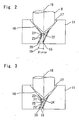
- Fig. 2 is an enlarged view showing the fuel flow path between the valve member and the valve seat of the fuel injection valve shown in Fig. 1 , in which the state of the valve member 8 being in an open valve position separated from the valve seat 11 is illustrated.
- the valve seat 11 is provided with a valve seat surface 17 defining a conical flow path 16 including a conical surface having a diameter gradually decreases in the direction of fuel flow, and the injection port 15 connected at the downstream side of the conical flow path 16 is provided with a cylindrical surface 20 having a central axis 19 slanted with respect to the central axis 18 of the conical flow path 16.
- the valve member 8 has a substantially cone-shaped tip and is brought into a contacting and separating relationship with respect to the valve seal surface 17 to control the supply of the fuel into the injection port 15.
- the valve seat 11 further comprises an intermediate flow path 22 having a cylindrical surface 21 coaxial to the conical flow path 16 between the conical flow path 16 the injection port 15 (that is, the central axis of the intermediate flow path 22 coincides with the central axis 18 of the conical flow path 16).
- the intermediate flow path 22 Since the diameter of the intermediate flow path 22 is substantially equal to that of the injection port 15, the intermediate flow path 22 appears only partially between the conical flow path 16 and the injection port 15, and the cylindrical surface 20 of the injection port 15 has one portion (the portion on the side where the change in the angle relative to the valve seat surface 17 is small) connected to the valve seat surface 17 which is the conical surface of the conical flow path 16 and has another portion (the portion on the side where the change in the angle relative to the valve seat surface 17 is large) connected to the cylindrical surface 21 of the intermediate flow path 22. Therefore, the resulted configuration is such that that portion where the change in the angle between the valve seat surface 17 and the cylindrical surface 20 of the injection port 15 is large is cut off.
- the flow of the fuel at this portion is made smooth to reduce the loss and to suppress the stagnation, so that the accumulation of the carbon deposit 23 is small as illustrated.
- the circumference on the upstream side of the injection port 15 is connected at one portion to the intermediate flow path 22 and at a still another portion to the valve seat surface 17, so that the number of the portions at which the fuel flow direction changes is small as compared to that where entire circumference on the upstream side of the injection port 15 is connected to the intermediate flow path 22 and where the flow path is bent. It is to be noted that the particularly advantageous results due to the intermediate flow path 22 can be obtained when the slant angle of the injection ports is large, such as 30 degrees or more.
- Fig. 3 is an enlarged view showing the fuel flow path in another embodiment of the fuel injection valve of the present invention.
- the intermediate flow path 24 has a tapered conical surface 25 that is connected to the downstream side end portion of the cylindrical surface 21 and that has a diameter gradually decreases in the direction of flow of the fuel, and the conical surface 25 has one portion of the circumference of the upper end of the cylindrical surface 20 of the injection port 15 previously described.
- the apex angle B of the conical surface 25 of the intermediate flow path 24 is made smaller than the apex angle A of the conical surface of the valve seat surface 17 (B ⁇ A).
- the upper end of the injection port 15 is connected to the valve seat surface 17 which is the conical surface of the conical flow path 16, a cylindrical surface 21 of the intermediate flow path 24 and the conical surface 25 of the intermediate 24 and has a configuration that has no significant angle change between the valve seat surface 17 and the injection port 15. Therefore, it is difficult for the carbon deposit 23 that may be formed on the flow path walls to deposits and, even when deposited, the amount may be small.
- the inner diameter of the injection port 15 is small as compared to that of the fuel injection valve illustrated in Fig. 2 , and it is prevented that the lower end portion of the intermediate flow path 24 which is the cylindrical flow path cuts into the cylindrical surface 20 of the injection port 15 and forms a dimple 26 therein as shown in Fig. 5 .
- the advantageous effect obtained by the use of the fuel injection valve of the present invention in an internal combustion engine is that, even when a large slant angle is given to the direction of the fuel injection with respect to the direction of installation of the fuel injection valve, the decrease in amount of fuel injection due to the carbon deposit and the deterioration in atomization of the injected fuel can be minimized, so that the initial engine performance of the new engine can be maintained even after a long time use.
Landscapes
- Engineering & Computer Science (AREA)
- Chemical & Material Sciences (AREA)
- Combustion & Propulsion (AREA)
- Mechanical Engineering (AREA)
- General Engineering & Computer Science (AREA)
- Physics & Mathematics (AREA)
- Electromagnetism (AREA)
- Fuel-Injection Apparatus (AREA)
Claims (3)
- Kraftstoffeinspritzventil (1), aufweisend:einen Ventilsitz (11) mit einer Einspritzöffnung (15), mit einer Ventilsitzfläche (17), die einen konischen Strömungsweg (16) mit einer konischen Fläche, die allmählich in der Strömungsrichtung des Kraftstoffs im Durchmesser abnimmt, und eine zylindrische Fläche (20), die eine Mittelachse (19) aufweist, die bezüglich der Mittelachse (18) des Strömungswegs konisch geneigt ist, definiert;ein Ventilelement (8), das eine im Wesentlichen konischen Spitze zum in Kontakt bringen und Trennen bezüglich der Ventilsitzfläche (17) aufweist, um die Zufuhr von Kraftstoff in die Einspritzöffnung (15) zu steuern; undein Zwischenströmungsweg (22), der eine zylindrische Fläche (21) koaxial zu dem konischen Strömungsweg (16) aufweist, zwischen dem konischen Strömungsweg (16) und der Einspritzöffnung (15) vorgesehen ist;gekennzeichnet durch ferner aufweisend:einen Aktuator (3, 4, 5, 6) zum Betätigen des Ventilelements, wobeidie Einspritzöffnung (15) einen Abschnitt der zylindrischen Fläche (20), der mit der konischen Fläche des konischen Strömungsweg (16) verbunden ist und einen weiteren Abschnitt der zylindrischen Fläche (20), der mit der zylindrischen Fläche (21) des Zwischenströmungswegs (22) verbunden ist, aufweist;wodurch die Verursachung von Stagnation der Strömung des Kraftstoffs unterdrückt wird.
- Kraftstoffeinspritzventil (1) wie in Anspruch 1 beansprucht, wobei der Zwischenströmungsweg (22) eine konisch zulaufende Fläche (25) aufweist, die mit einer stromabwärtigen Endseite der zylindrische Fläche (21) verbunden ist, aufweist, und der einen Durchmesser aufweist, der allmählich in Richtung der Strömung des Kraftstoffs abnimmt, und wobei noch ein weiterer Abschnitt der zylindrischen Fläche (21) der Einspritzöffnung (15) mit der konische zulaufenden Fläche (25) des Zwischenströmungswegs (22) verbunden ist.
- Kraftstoffeinspritzventil (1) wie in Anspruch 2 beansprucht, wobei ein Kegelspitzenwinkel der konischen Oberfläche des Zwischenströmungswegs (22) kleiner als ein Kegelspitzenwinkel der Ventilsitzfläche (17) ist.
Applications Claiming Priority (1)
| Application Number | Priority Date | Filing Date | Title |
|---|---|---|---|
| PCT/JP2003/001125 WO2004070200A1 (ja) | 2003-02-04 | 2003-02-04 | 燃料噴射弁 |
Publications (3)
| Publication Number | Publication Date |
|---|---|
| EP1596059A1 EP1596059A1 (de) | 2005-11-16 |
| EP1596059A4 EP1596059A4 (de) | 2009-12-23 |
| EP1596059B1 true EP1596059B1 (de) | 2013-11-06 |
Family
ID=32843961
Family Applications (1)
| Application Number | Title | Priority Date | Filing Date |
|---|---|---|---|
| EP03815731.9A Expired - Lifetime EP1596059B1 (de) | 2003-02-04 | 2003-02-04 | Kraftstoffeinspritzventil |
Country Status (5)
| Country | Link |
|---|---|
| US (1) | US7337986B2 (de) |
| EP (1) | EP1596059B1 (de) |
| JP (1) | JP4097155B2 (de) |
| CN (1) | CN100462550C (de) |
| WO (1) | WO2004070200A1 (de) |
Families Citing this family (3)
| Publication number | Priority date | Publication date | Assignee | Title |
|---|---|---|---|---|
| US9546633B2 (en) | 2012-03-30 | 2017-01-17 | Electro-Motive Diesel, Inc. | Nozzle for skewed fuel injection |
| DE102016211688A1 (de) * | 2016-06-29 | 2018-01-04 | Robert Bosch Gmbh | Injektor zum Einspritzen eines Fluids mit sich verjüngendem Einströmbereich einer Durchgangsöffnung |
| US20210239082A1 (en) * | 2018-04-25 | 2021-08-05 | Robert Bosch Gmbh | Fuel Injector Valve Seat Assembly Including an Insert that Forms a Valve Seat |
Family Cites Families (12)
| Publication number | Priority date | Publication date | Assignee | Title |
|---|---|---|---|---|
| US4153205A (en) * | 1977-10-19 | 1979-05-08 | Allis-Chalmers Corporation | Short seat fuel injection nozzle valve |
| DE2902417A1 (de) * | 1979-01-23 | 1980-07-31 | Maschf Augsburg Nuernberg Ag | Kraftstoff-einspritzduese fuer brennkraftmaschinen |
| US5033679A (en) * | 1987-10-30 | 1991-07-23 | Golev Vladislav I | Injector nozzle for a diesel engine |
| US5218943A (en) * | 1991-01-07 | 1993-06-15 | Toyota Jidosha Kabushiki Kaisha | Fuel injection apparatus for internal combustion engine |
| GB9425652D0 (en) * | 1994-12-20 | 1995-02-22 | Lucas Ind Plc | Fuel injection nozzle |
| JP3075201B2 (ja) | 1996-12-20 | 2000-08-14 | 株式会社デンソー | 燃料噴射弁 |
| JP3933739B2 (ja) | 1997-01-30 | 2007-06-20 | 三菱電機株式会社 | 燃料噴射弁 |
| DE29713628U1 (de) * | 1997-07-31 | 1998-11-26 | Robert Bosch Gmbh, 70469 Stuttgart | Kraftstoffeinspritzdüse |
| JP2000303934A (ja) * | 1999-04-19 | 2000-10-31 | Aisan Ind Co Ltd | 燃料噴射ノズル |
| DE10049518B4 (de) * | 2000-10-06 | 2005-11-24 | Robert Bosch Gmbh | Brennstoffeinspritzventil |
| DE10059009A1 (de) * | 2000-11-28 | 2002-05-29 | Bosch Gmbh Robert | Brennstoffeinspritzanlage |
| JP3614381B2 (ja) * | 2001-06-05 | 2005-01-26 | 三菱電機株式会社 | 燃料噴射装置 |
-
2003
- 2003-02-04 EP EP03815731.9A patent/EP1596059B1/de not_active Expired - Lifetime
- 2003-02-04 CN CNB038258951A patent/CN100462550C/zh not_active Expired - Fee Related
- 2003-02-04 US US10/544,390 patent/US7337986B2/en not_active Expired - Fee Related
- 2003-02-04 JP JP2004564060A patent/JP4097155B2/ja not_active Expired - Fee Related
- 2003-02-04 WO PCT/JP2003/001125 patent/WO2004070200A1/ja not_active Ceased
Also Published As
| Publication number | Publication date |
|---|---|
| JP4097155B2 (ja) | 2008-06-11 |
| CN1738968A (zh) | 2006-02-22 |
| US7337986B2 (en) | 2008-03-04 |
| US20060144958A1 (en) | 2006-07-06 |
| EP1596059A4 (de) | 2009-12-23 |
| CN100462550C (zh) | 2009-02-18 |
| WO2004070200A1 (ja) | 2004-08-19 |
| EP1596059A1 (de) | 2005-11-16 |
| JPWO2004070200A1 (ja) | 2006-05-25 |
Similar Documents
| Publication | Publication Date | Title |
|---|---|---|
| US6826833B1 (en) | Fuel injection valve and a method for manufacturing exit outlets on the valve | |
| EP1224391B1 (de) | Brennstoffdirekteinspritzung in einer brennkraftmaschine | |
| KR100282108B1 (ko) | 연료분사밸브 | |
| US6578778B2 (en) | Fuel injection valve | |
| US20130075501A1 (en) | Fuel injector | |
| KR100717526B1 (ko) | 연료 분사 밸브 | |
| EP1596059B1 (de) | Kraftstoffeinspritzventil | |
| JP2013194725A (ja) | 燃料噴射弁 | |
| US9334842B2 (en) | Fuel injection valve for internal combustion engine | |
| JP6780087B2 (ja) | 燃料噴射装置 | |
| US6983900B2 (en) | Fuel injector | |
| JP4127703B2 (ja) | 燃料噴射装置 | |
| JP2009162239A (ja) | 燃料噴射弁および内燃機関 | |
| KR100693597B1 (ko) | 연료 분사 밸브 | |
| JP2004506138A (ja) | 燃料噴射弁 | |
| JP3730951B2 (ja) | 燃料噴射弁 | |
| JP4305858B2 (ja) | 燃料噴射弁 | |
| JP7610495B2 (ja) | 燃料噴射装置 | |
| WO2019107126A1 (ja) | 燃料噴射装置 | |
| JP4191760B2 (ja) | 燃料噴射弁 | |
| JP4191761B2 (ja) | 燃料噴射弁 | |
| CN111356835B (zh) | 燃料喷射阀 | |
| JP2006138271A (ja) | 燃料噴射弁 | |
| JP2016089660A (ja) | 燃料噴射装置 | |
| JP2007071106A (ja) | 燃料噴射装置 |
Legal Events
| Date | Code | Title | Description |
|---|---|---|---|
| PUAI | Public reference made under article 153(3) epc to a published international application that has entered the european phase |
Free format text: ORIGINAL CODE: 0009012 |
|
| 17P | Request for examination filed |
Effective date: 20050824 |
|
| AK | Designated contracting states |
Kind code of ref document: A1 Designated state(s): AT BE BG CH CY CZ DE DK EE ES FI FR GB GR HU IE IT LI LU MC NL PT SE SI SK TR |
|
| RBV | Designated contracting states (corrected) |
Designated state(s): AT BE BG CH CY CZ DE DK EE ES FI FR GB GR HU IE IT LI LU MC NL PT SE SI SK TR |
|
| RAP1 | Party data changed (applicant data changed or rights of an application transferred) |
Owner name: MITSUBISHI DENKI KABUSHIKI KAISHA |
|
| RBV | Designated contracting states (corrected) |
Designated state(s): DE FR |
|
| A4 | Supplementary search report drawn up and despatched |
Effective date: 20091124 |
|
| RIC1 | Information provided on ipc code assigned before grant |
Ipc: F02M 61/16 20060101ALI20091118BHEP Ipc: F02M 61/18 20060101AFI20040824BHEP Ipc: F02M 51/06 20060101ALI20091118BHEP |
|
| 17Q | First examination report despatched |
Effective date: 20101119 |
|
| GRAP | Despatch of communication of intention to grant a patent |
Free format text: ORIGINAL CODE: EPIDOSNIGR1 |
|
| RIC1 | Information provided on ipc code assigned before grant |
Ipc: F02M 61/16 20060101ALI20130515BHEP Ipc: F02M 51/06 20060101ALI20130515BHEP Ipc: F02M 61/18 20060101AFI20130515BHEP |
|
| INTG | Intention to grant announced |
Effective date: 20130604 |
|
| GRAS | Grant fee paid |
Free format text: ORIGINAL CODE: EPIDOSNIGR3 |
|
| GRAA | (expected) grant |
Free format text: ORIGINAL CODE: 0009210 |
|
| AK | Designated contracting states |
Kind code of ref document: B1 Designated state(s): DE FR |
|
| RIN1 | Information on inventor provided before grant (corrected) |
Inventor name: FUKUTOMI, NORIHISA |
|
| REG | Reference to a national code |
Ref country code: DE Ref legal event code: R096 Ref document number: 60345262 Country of ref document: DE Effective date: 20140102 |
|
| REG | Reference to a national code |
Ref country code: DE Ref legal event code: R097 Ref document number: 60345262 Country of ref document: DE |
|
| PLBE | No opposition filed within time limit |
Free format text: ORIGINAL CODE: 0009261 |
|
| STAA | Information on the status of an ep patent application or granted ep patent |
Free format text: STATUS: NO OPPOSITION FILED WITHIN TIME LIMIT |
|
| 26N | No opposition filed |
Effective date: 20140807 |
|
| REG | Reference to a national code |
Ref country code: DE Ref legal event code: R097 Ref document number: 60345262 Country of ref document: DE Effective date: 20140807 |
|
| REG | Reference to a national code |
Ref country code: FR Ref legal event code: PLFP Year of fee payment: 14 |
|
| PGFP | Annual fee paid to national office [announced via postgrant information from national office to epo] |
Ref country code: DE Payment date: 20160127 Year of fee payment: 14 |
|
| REG | Reference to a national code |
Ref country code: DE Ref legal event code: R084 Ref document number: 60345262 Country of ref document: DE |
|
| PGFP | Annual fee paid to national office [announced via postgrant information from national office to epo] |
Ref country code: FR Payment date: 20160108 Year of fee payment: 14 |
|
| REG | Reference to a national code |
Ref country code: DE Ref legal event code: R119 Ref document number: 60345262 Country of ref document: DE |
|
| REG | Reference to a national code |
Ref country code: FR Ref legal event code: ST Effective date: 20171031 |
|
| PG25 | Lapsed in a contracting state [announced via postgrant information from national office to epo] |
Ref country code: DE Free format text: LAPSE BECAUSE OF NON-PAYMENT OF DUE FEES Effective date: 20170901 Ref country code: FR Free format text: LAPSE BECAUSE OF NON-PAYMENT OF DUE FEES Effective date: 20170228 |