EP1595686B1 - Unit for production of tubular resin film - Google Patents
Unit for production of tubular resin film Download PDFInfo
- Publication number
- EP1595686B1 EP1595686B1 EP03786257A EP03786257A EP1595686B1 EP 1595686 B1 EP1595686 B1 EP 1595686B1 EP 03786257 A EP03786257 A EP 03786257A EP 03786257 A EP03786257 A EP 03786257A EP 1595686 B1 EP1595686 B1 EP 1595686B1
- Authority
- EP
- European Patent Office
- Prior art keywords
- resin film
- tubular resin
- film
- tubular
- stretching
- Prior art date
- Legal status (The legal status is an assumption and is not a legal conclusion. Google has not performed a legal analysis and makes no representation as to the accuracy of the status listed.)
- Expired - Lifetime
Links
- 229920005989 resin Polymers 0.000 title claims abstract description 281
- 239000011347 resin Substances 0.000 title claims abstract description 281
- 238000004519 manufacturing process Methods 0.000 title claims description 69
- 239000011148 porous material Substances 0.000 claims description 27
- 238000013022 venting Methods 0.000 claims description 23
- 238000011144 upstream manufacturing Methods 0.000 claims description 5
- 229920005992 thermoplastic resin Polymers 0.000 description 71
- 239000007789 gas Substances 0.000 description 54
- 238000010276 construction Methods 0.000 description 30
- 238000010438 heat treatment Methods 0.000 description 30
- 238000005520 cutting process Methods 0.000 description 28
- 238000000034 method Methods 0.000 description 28
- 230000000087 stabilizing effect Effects 0.000 description 26
- 238000001125 extrusion Methods 0.000 description 19
- 239000000314 lubricant Substances 0.000 description 17
- 230000007246 mechanism Effects 0.000 description 16
- 239000000463 material Substances 0.000 description 13
- 239000004973 liquid crystal related substance Substances 0.000 description 12
- 230000003078 antioxidant effect Effects 0.000 description 10
- 229910052751 metal Inorganic materials 0.000 description 10
- 239000002184 metal Substances 0.000 description 10
- 239000003570 air Substances 0.000 description 9
- 239000003963 antioxidant agent Substances 0.000 description 9
- 239000002994 raw material Substances 0.000 description 9
- 230000009477 glass transition Effects 0.000 description 8
- 230000008569 process Effects 0.000 description 8
- 239000000126 substance Substances 0.000 description 8
- 239000000654 additive Substances 0.000 description 7
- 230000008602 contraction Effects 0.000 description 7
- 238000004804 winding Methods 0.000 description 7
- 125000004122 cyclic group Chemical group 0.000 description 6
- 238000005259 measurement Methods 0.000 description 6
- 229920000098 polyolefin Polymers 0.000 description 6
- 238000001816 cooling Methods 0.000 description 5
- 235000014113 dietary fatty acids Nutrition 0.000 description 5
- 230000000694 effects Effects 0.000 description 5
- 239000000194 fatty acid Substances 0.000 description 5
- 229930195729 fatty acid Natural products 0.000 description 5
- 150000004665 fatty acids Chemical class 0.000 description 5
- 230000003449 preventive effect Effects 0.000 description 5
- 230000002829 reductive effect Effects 0.000 description 5
- 230000001105 regulatory effect Effects 0.000 description 5
- JFNLZVQOOSMTJK-KNVOCYPGSA-N norbornene Chemical compound C1[C@@H]2CC[C@H]1C=C2 JFNLZVQOOSMTJK-KNVOCYPGSA-N 0.000 description 4
- 239000002530 phenolic antioxidant Substances 0.000 description 4
- 238000002834 transmittance Methods 0.000 description 4
- 239000004594 Masterbatch (MB) Substances 0.000 description 3
- BGYHLZZASRKEJE-UHFFFAOYSA-N [3-[3-(3,5-ditert-butyl-4-hydroxyphenyl)propanoyloxy]-2,2-bis[3-(3,5-ditert-butyl-4-hydroxyphenyl)propanoyloxymethyl]propyl] 3-(3,5-ditert-butyl-4-hydroxyphenyl)propanoate Chemical compound CC(C)(C)C1=C(O)C(C(C)(C)C)=CC(CCC(=O)OCC(COC(=O)CCC=2C=C(C(O)=C(C=2)C(C)(C)C)C(C)(C)C)(COC(=O)CCC=2C=C(C(O)=C(C=2)C(C)(C)C)C(C)(C)C)COC(=O)CCC=2C=C(C(O)=C(C=2)C(C)(C)C)C(C)(C)C)=C1 BGYHLZZASRKEJE-UHFFFAOYSA-N 0.000 description 3
- 239000012080 ambient air Substances 0.000 description 3
- 238000007664 blowing Methods 0.000 description 3
- 238000004891 communication Methods 0.000 description 3
- 230000006870 function Effects 0.000 description 3
- 238000000465 moulding Methods 0.000 description 3
- 230000003287 optical effect Effects 0.000 description 3
- -1 polyethylene Polymers 0.000 description 3
- 239000002904 solvent Substances 0.000 description 3
- 238000000807 solvent casting Methods 0.000 description 3
- VNQNXQYZMPJLQX-UHFFFAOYSA-N 1,3,5-tris[(3,5-ditert-butyl-4-hydroxyphenyl)methyl]-1,3,5-triazinane-2,4,6-trione Chemical compound CC(C)(C)C1=C(O)C(C(C)(C)C)=CC(CN2C(N(CC=3C=C(C(O)=C(C=3)C(C)(C)C)C(C)(C)C)C(=O)N(CC=3C=C(C(O)=C(C=3)C(C)(C)C)C(C)(C)C)C2=O)=O)=C1 VNQNXQYZMPJLQX-UHFFFAOYSA-N 0.000 description 2
- WKBPZYKAUNRMKP-UHFFFAOYSA-N 1-[2-(2,4-dichlorophenyl)pentyl]1,2,4-triazole Chemical compound C=1C=C(Cl)C=C(Cl)C=1C(CCC)CN1C=NC=N1 WKBPZYKAUNRMKP-UHFFFAOYSA-N 0.000 description 2
- XEEYBQQBJWHFJM-UHFFFAOYSA-N Iron Chemical compound [Fe] XEEYBQQBJWHFJM-UHFFFAOYSA-N 0.000 description 2
- 229920000106 Liquid crystal polymer Polymers 0.000 description 2
- 241000282320 Panthera leo Species 0.000 description 2
- NBIIXXVUZAFLBC-UHFFFAOYSA-N Phosphoric acid Chemical compound OP(O)(O)=O NBIIXXVUZAFLBC-UHFFFAOYSA-N 0.000 description 2
- 230000002411 adverse Effects 0.000 description 2
- 101150059062 apln gene Proteins 0.000 description 2
- 230000008859 change Effects 0.000 description 2
- 238000006243 chemical reaction Methods 0.000 description 2
- 230000001276 controlling effect Effects 0.000 description 2
- 229920001577 copolymer Polymers 0.000 description 2
- 238000005984 hydrogenation reaction Methods 0.000 description 2
- 239000005001 laminate film Substances 0.000 description 2
- 239000000178 monomer Substances 0.000 description 2
- FTQWRYSLUYAIRQ-UHFFFAOYSA-N n-[(octadecanoylamino)methyl]octadecanamide Chemical compound CCCCCCCCCCCCCCCCCC(=O)NCNC(=O)CCCCCCCCCCCCCCCCC FTQWRYSLUYAIRQ-UHFFFAOYSA-N 0.000 description 2
- SSDSCDGVMJFTEQ-UHFFFAOYSA-N octadecyl 3-(3,5-ditert-butyl-4-hydroxyphenyl)propanoate Chemical compound CCCCCCCCCCCCCCCCCCOC(=O)CCC1=CC(C(C)(C)C)=C(O)C(C(C)(C)C)=C1 SSDSCDGVMJFTEQ-UHFFFAOYSA-N 0.000 description 2
- 230000000149 penetrating effect Effects 0.000 description 2
- 229920000515 polycarbonate Polymers 0.000 description 2
- 239000004417 polycarbonate Substances 0.000 description 2
- 229920006300 shrink film Polymers 0.000 description 2
- XHSVWKJCURCWFU-UHFFFAOYSA-N 19-[3-(19-amino-19-oxononadecyl)phenyl]nonadecanamide Chemical compound NC(=O)CCCCCCCCCCCCCCCCCCC1=CC=CC(CCCCCCCCCCCCCCCCCCC(N)=O)=C1 XHSVWKJCURCWFU-UHFFFAOYSA-N 0.000 description 1
- VSAWBBYYMBQKIK-UHFFFAOYSA-N 4-[[3,5-bis[(3,5-ditert-butyl-4-hydroxyphenyl)methyl]-2,4,6-trimethylphenyl]methyl]-2,6-ditert-butylphenol Chemical compound CC1=C(CC=2C=C(C(O)=C(C=2)C(C)(C)C)C(C)(C)C)C(C)=C(CC=2C=C(C(O)=C(C=2)C(C)(C)C)C(C)(C)C)C(C)=C1CC1=CC(C(C)(C)C)=C(O)C(C(C)(C)C)=C1 VSAWBBYYMBQKIK-UHFFFAOYSA-N 0.000 description 1
- 241000239290 Araneae Species 0.000 description 1
- 239000004215 Carbon black (E152) Substances 0.000 description 1
- 239000004985 Discotic Liquid Crystal Substance Substances 0.000 description 1
- 229920000219 Ethylene vinyl alcohol Polymers 0.000 description 1
- YCKRFDGAMUMZLT-UHFFFAOYSA-N Fluorine atom Chemical compound [F] YCKRFDGAMUMZLT-UHFFFAOYSA-N 0.000 description 1
- 239000004988 Nematic liquid crystal Substances 0.000 description 1
- 239000004952 Polyamide Substances 0.000 description 1
- 239000004695 Polyether sulfone Substances 0.000 description 1
- 239000004698 Polyethylene Substances 0.000 description 1
- 239000004743 Polypropylene Substances 0.000 description 1
- 239000004793 Polystyrene Substances 0.000 description 1
- 229910001069 Ti alloy Inorganic materials 0.000 description 1
- CGRTZESQZZGAAU-UHFFFAOYSA-N [2-[3-[1-[3-(3-tert-butyl-4-hydroxy-5-methylphenyl)propanoyloxy]-2-methylpropan-2-yl]-2,4,8,10-tetraoxaspiro[5.5]undecan-9-yl]-2-methylpropyl] 3-(3-tert-butyl-4-hydroxy-5-methylphenyl)propanoate Chemical compound CC(C)(C)C1=C(O)C(C)=CC(CCC(=O)OCC(C)(C)C2OCC3(CO2)COC(OC3)C(C)(C)COC(=O)CCC=2C=C(C(O)=C(C)C=2)C(C)(C)C)=C1 CGRTZESQZZGAAU-UHFFFAOYSA-N 0.000 description 1
- 230000009471 action Effects 0.000 description 1
- 230000000996 additive effect Effects 0.000 description 1
- 230000001476 alcoholic effect Effects 0.000 description 1
- 229910000147 aluminium phosphate Inorganic materials 0.000 description 1
- 239000012298 atmosphere Substances 0.000 description 1
- 230000004888 barrier function Effects 0.000 description 1
- 230000006399 behavior Effects 0.000 description 1
- 238000005266 casting Methods 0.000 description 1
- 239000000919 ceramic Substances 0.000 description 1
- 229910010293 ceramic material Inorganic materials 0.000 description 1
- 239000011248 coating agent Substances 0.000 description 1
- 238000000576 coating method Methods 0.000 description 1
- 239000003086 colorant Substances 0.000 description 1
- 238000007796 conventional method Methods 0.000 description 1
- 230000010485 coping Effects 0.000 description 1
- 239000007822 coupling agent Substances 0.000 description 1
- 230000007423 decrease Effects 0.000 description 1
- 238000013461 design Methods 0.000 description 1
- 238000011161 development Methods 0.000 description 1
- 238000007599 discharging Methods 0.000 description 1
- 239000006185 dispersion Substances 0.000 description 1
- 239000000975 dye Substances 0.000 description 1
- 230000007613 environmental effect Effects 0.000 description 1
- 150000002148 esters Chemical class 0.000 description 1
- ZJOLCKGSXLIVAA-UHFFFAOYSA-N ethene;octadecanamide Chemical compound C=C.CCCCCCCCCCCCCCCCCC(N)=O.CCCCCCCCCCCCCCCCCC(N)=O ZJOLCKGSXLIVAA-UHFFFAOYSA-N 0.000 description 1
- 239000011737 fluorine Substances 0.000 description 1
- 229910052731 fluorine Inorganic materials 0.000 description 1
- 239000011888 foil Substances 0.000 description 1
- 235000013305 food Nutrition 0.000 description 1
- 239000011521 glass Substances 0.000 description 1
- FEEPBTVZSYQUDP-UHFFFAOYSA-N heptatriacontanediamide Chemical compound NC(=O)CCCCCCCCCCCCCCCCCCCCCCCCCCCCCCCCCCCC(N)=O FEEPBTVZSYQUDP-UHFFFAOYSA-N 0.000 description 1
- 229920001519 homopolymer Polymers 0.000 description 1
- 229930195733 hydrocarbon Natural products 0.000 description 1
- 150000002430 hydrocarbons Chemical class 0.000 description 1
- 239000012535 impurity Substances 0.000 description 1
- 239000011261 inert gas Substances 0.000 description 1
- 239000011256 inorganic filler Substances 0.000 description 1
- 229910003475 inorganic filler Inorganic materials 0.000 description 1
- 238000009434 installation Methods 0.000 description 1
- 229910052742 iron Inorganic materials 0.000 description 1
- 230000001788 irregular Effects 0.000 description 1
- 239000004611 light stabiliser Substances 0.000 description 1
- 230000007774 longterm Effects 0.000 description 1
- 238000012423 maintenance Methods 0.000 description 1
- AUHZEENZYGFFBQ-UHFFFAOYSA-N mesitylene Substances CC1=CC(C)=CC(C)=C1 AUHZEENZYGFFBQ-UHFFFAOYSA-N 0.000 description 1
- 235000013872 montan acid ester Nutrition 0.000 description 1
- 238000005121 nitriding Methods 0.000 description 1
- LYRFLYHAGKPMFH-UHFFFAOYSA-N octadecanamide Chemical compound CCCCCCCCCCCCCCCCCC(N)=O LYRFLYHAGKPMFH-UHFFFAOYSA-N 0.000 description 1
- 239000003960 organic solvent Substances 0.000 description 1
- 238000004806 packaging method and process Methods 0.000 description 1
- 230000036961 partial effect Effects 0.000 description 1
- 239000008188 pellet Substances 0.000 description 1
- 230000000737 periodic effect Effects 0.000 description 1
- 230000035699 permeability Effects 0.000 description 1
- 230000000704 physical effect Effects 0.000 description 1
- 239000000049 pigment Substances 0.000 description 1
- 238000007747 plating Methods 0.000 description 1
- 238000005498 polishing Methods 0.000 description 1
- 229920002647 polyamide Polymers 0.000 description 1
- 229920001230 polyarylate Polymers 0.000 description 1
- 229920000728 polyester Polymers 0.000 description 1
- 229920006393 polyether sulfone Polymers 0.000 description 1
- 229920000573 polyethylene Polymers 0.000 description 1
- 229920000642 polymer Polymers 0.000 description 1
- 229920002959 polymer blend Polymers 0.000 description 1
- 229920001155 polypropylene Polymers 0.000 description 1
- 229920001296 polysiloxane Polymers 0.000 description 1
- 229920002223 polystyrene Polymers 0.000 description 1
- 239000000843 powder Substances 0.000 description 1
- 238000012545 processing Methods 0.000 description 1
- 230000009467 reduction Effects 0.000 description 1
- 238000012827 research and development Methods 0.000 description 1
- 230000000717 retained effect Effects 0.000 description 1
- 150000003839 salts Chemical class 0.000 description 1
- 238000007127 saponification reaction Methods 0.000 description 1
- 229920002379 silicone rubber Polymers 0.000 description 1
- 239000004945 silicone rubber Substances 0.000 description 1
- 239000000344 soap Substances 0.000 description 1
- 239000007779 soft material Substances 0.000 description 1
- 239000000243 solution Substances 0.000 description 1
- 239000010935 stainless steel Substances 0.000 description 1
- 229910001220 stainless steel Inorganic materials 0.000 description 1
- 239000004094 surface-active agent Substances 0.000 description 1
- 229920002554 vinyl polymer Polymers 0.000 description 1
- XLYOFNOQVPJJNP-UHFFFAOYSA-N water Chemical compound O XLYOFNOQVPJJNP-UHFFFAOYSA-N 0.000 description 1
Images


Classifications
-
- B—PERFORMING OPERATIONS; TRANSPORTING
- B29—WORKING OF PLASTICS; WORKING OF SUBSTANCES IN A PLASTIC STATE IN GENERAL
- B29C—SHAPING OR JOINING OF PLASTICS; SHAPING OF MATERIAL IN A PLASTIC STATE, NOT OTHERWISE PROVIDED FOR; AFTER-TREATMENT OF THE SHAPED PRODUCTS, e.g. REPAIRING
- B29C55/00—Shaping by stretching, e.g. drawing through a die; Apparatus therefor
- B29C55/22—Shaping by stretching, e.g. drawing through a die; Apparatus therefor of tubes
- B29C55/24—Shaping by stretching, e.g. drawing through a die; Apparatus therefor of tubes radial
-
- B—PERFORMING OPERATIONS; TRANSPORTING
- B29—WORKING OF PLASTICS; WORKING OF SUBSTANCES IN A PLASTIC STATE IN GENERAL
- B29C—SHAPING OR JOINING OF PLASTICS; SHAPING OF MATERIAL IN A PLASTIC STATE, NOT OTHERWISE PROVIDED FOR; AFTER-TREATMENT OF THE SHAPED PRODUCTS, e.g. REPAIRING
- B29C48/00—Extrusion moulding, i.e. expressing the moulding material through a die or nozzle which imparts the desired form; Apparatus therefor
- B29C48/03—Extrusion moulding, i.e. expressing the moulding material through a die or nozzle which imparts the desired form; Apparatus therefor characterised by the shape of the extruded material at extrusion
- B29C48/09—Articles with cross-sections having partially or fully enclosed cavities, e.g. pipes or channels
- B29C48/10—Articles with cross-sections having partially or fully enclosed cavities, e.g. pipes or channels flexible, e.g. blown foils
-
- B—PERFORMING OPERATIONS; TRANSPORTING
- B29—WORKING OF PLASTICS; WORKING OF SUBSTANCES IN A PLASTIC STATE IN GENERAL
- B29C—SHAPING OR JOINING OF PLASTICS; SHAPING OF MATERIAL IN A PLASTIC STATE, NOT OTHERWISE PROVIDED FOR; AFTER-TREATMENT OF THE SHAPED PRODUCTS, e.g. REPAIRING
- B29C48/00—Extrusion moulding, i.e. expressing the moulding material through a die or nozzle which imparts the desired form; Apparatus therefor
- B29C48/25—Component parts, details or accessories; Auxiliary operations
- B29C48/30—Extrusion nozzles or dies
-
- B—PERFORMING OPERATIONS; TRANSPORTING
- B29—WORKING OF PLASTICS; WORKING OF SUBSTANCES IN A PLASTIC STATE IN GENERAL
- B29C—SHAPING OR JOINING OF PLASTICS; SHAPING OF MATERIAL IN A PLASTIC STATE, NOT OTHERWISE PROVIDED FOR; AFTER-TREATMENT OF THE SHAPED PRODUCTS, e.g. REPAIRING
- B29C48/00—Extrusion moulding, i.e. expressing the moulding material through a die or nozzle which imparts the desired form; Apparatus therefor
- B29C48/25—Component parts, details or accessories; Auxiliary operations
- B29C48/88—Thermal treatment of the stream of extruded material, e.g. cooling
- B29C48/90—Thermal treatment of the stream of extruded material, e.g. cooling with calibration or sizing, i.e. combined with fixing or setting of the final dimensions of the extruded article
- B29C48/901—Thermal treatment of the stream of extruded material, e.g. cooling with calibration or sizing, i.e. combined with fixing or setting of the final dimensions of the extruded article of hollow bodies
- B29C48/902—Thermal treatment of the stream of extruded material, e.g. cooling with calibration or sizing, i.e. combined with fixing or setting of the final dimensions of the extruded article of hollow bodies internally
-
- B—PERFORMING OPERATIONS; TRANSPORTING
- B29—WORKING OF PLASTICS; WORKING OF SUBSTANCES IN A PLASTIC STATE IN GENERAL
- B29C—SHAPING OR JOINING OF PLASTICS; SHAPING OF MATERIAL IN A PLASTIC STATE, NOT OTHERWISE PROVIDED FOR; AFTER-TREATMENT OF THE SHAPED PRODUCTS, e.g. REPAIRING
- B29C48/00—Extrusion moulding, i.e. expressing the moulding material through a die or nozzle which imparts the desired form; Apparatus therefor
- B29C48/25—Component parts, details or accessories; Auxiliary operations
- B29C48/88—Thermal treatment of the stream of extruded material, e.g. cooling
- B29C48/90—Thermal treatment of the stream of extruded material, e.g. cooling with calibration or sizing, i.e. combined with fixing or setting of the final dimensions of the extruded article
- B29C48/908—Thermal treatment of the stream of extruded material, e.g. cooling with calibration or sizing, i.e. combined with fixing or setting of the final dimensions of the extruded article characterised by calibrator surface, e.g. structure or holes for lubrication, cooling or venting
-
- B—PERFORMING OPERATIONS; TRANSPORTING
- B29—WORKING OF PLASTICS; WORKING OF SUBSTANCES IN A PLASTIC STATE IN GENERAL
- B29C—SHAPING OR JOINING OF PLASTICS; SHAPING OF MATERIAL IN A PLASTIC STATE, NOT OTHERWISE PROVIDED FOR; AFTER-TREATMENT OF THE SHAPED PRODUCTS, e.g. REPAIRING
- B29C55/00—Shaping by stretching, e.g. drawing through a die; Apparatus therefor
- B29C55/22—Shaping by stretching, e.g. drawing through a die; Apparatus therefor of tubes
- B29C55/26—Shaping by stretching, e.g. drawing through a die; Apparatus therefor of tubes biaxial
-
- B—PERFORMING OPERATIONS; TRANSPORTING
- B29—WORKING OF PLASTICS; WORKING OF SUBSTANCES IN A PLASTIC STATE IN GENERAL
- B29C—SHAPING OR JOINING OF PLASTICS; SHAPING OF MATERIAL IN A PLASTIC STATE, NOT OTHERWISE PROVIDED FOR; AFTER-TREATMENT OF THE SHAPED PRODUCTS, e.g. REPAIRING
- B29C2793/00—Shaping techniques involving a cutting or machining operation
- B29C2793/009—Shaping techniques involving a cutting or machining operation after shaping
-
- B—PERFORMING OPERATIONS; TRANSPORTING
- B29—WORKING OF PLASTICS; WORKING OF SUBSTANCES IN A PLASTIC STATE IN GENERAL
- B29C—SHAPING OR JOINING OF PLASTICS; SHAPING OF MATERIAL IN A PLASTIC STATE, NOT OTHERWISE PROVIDED FOR; AFTER-TREATMENT OF THE SHAPED PRODUCTS, e.g. REPAIRING
- B29C2948/00—Indexing scheme relating to extrusion moulding
- B29C2948/92—Measuring, controlling or regulating
- B29C2948/92009—Measured parameter
- B29C2948/92114—Dimensions
- B29C2948/92152—Thickness
-
- B—PERFORMING OPERATIONS; TRANSPORTING
- B29—WORKING OF PLASTICS; WORKING OF SUBSTANCES IN A PLASTIC STATE IN GENERAL
- B29C—SHAPING OR JOINING OF PLASTICS; SHAPING OF MATERIAL IN A PLASTIC STATE, NOT OTHERWISE PROVIDED FOR; AFTER-TREATMENT OF THE SHAPED PRODUCTS, e.g. REPAIRING
- B29C2948/00—Indexing scheme relating to extrusion moulding
- B29C2948/92—Measuring, controlling or regulating
- B29C2948/92504—Controlled parameter
- B29C2948/92514—Pressure
-
- B—PERFORMING OPERATIONS; TRANSPORTING
- B29—WORKING OF PLASTICS; WORKING OF SUBSTANCES IN A PLASTIC STATE IN GENERAL
- B29C—SHAPING OR JOINING OF PLASTICS; SHAPING OF MATERIAL IN A PLASTIC STATE, NOT OTHERWISE PROVIDED FOR; AFTER-TREATMENT OF THE SHAPED PRODUCTS, e.g. REPAIRING
- B29C2948/00—Indexing scheme relating to extrusion moulding
- B29C2948/92—Measuring, controlling or regulating
- B29C2948/92504—Controlled parameter
- B29C2948/92609—Dimensions
- B29C2948/92638—Length
-
- B—PERFORMING OPERATIONS; TRANSPORTING
- B29—WORKING OF PLASTICS; WORKING OF SUBSTANCES IN A PLASTIC STATE IN GENERAL
- B29C—SHAPING OR JOINING OF PLASTICS; SHAPING OF MATERIAL IN A PLASTIC STATE, NOT OTHERWISE PROVIDED FOR; AFTER-TREATMENT OF THE SHAPED PRODUCTS, e.g. REPAIRING
- B29C2948/00—Indexing scheme relating to extrusion moulding
- B29C2948/92—Measuring, controlling or regulating
- B29C2948/92504—Controlled parameter
- B29C2948/92609—Dimensions
- B29C2948/92647—Thickness
-
- B—PERFORMING OPERATIONS; TRANSPORTING
- B29—WORKING OF PLASTICS; WORKING OF SUBSTANCES IN A PLASTIC STATE IN GENERAL
- B29C—SHAPING OR JOINING OF PLASTICS; SHAPING OF MATERIAL IN A PLASTIC STATE, NOT OTHERWISE PROVIDED FOR; AFTER-TREATMENT OF THE SHAPED PRODUCTS, e.g. REPAIRING
- B29C2948/00—Indexing scheme relating to extrusion moulding
- B29C2948/92—Measuring, controlling or regulating
- B29C2948/92504—Controlled parameter
- B29C2948/92704—Temperature
-
- B—PERFORMING OPERATIONS; TRANSPORTING
- B29—WORKING OF PLASTICS; WORKING OF SUBSTANCES IN A PLASTIC STATE IN GENERAL
- B29C—SHAPING OR JOINING OF PLASTICS; SHAPING OF MATERIAL IN A PLASTIC STATE, NOT OTHERWISE PROVIDED FOR; AFTER-TREATMENT OF THE SHAPED PRODUCTS, e.g. REPAIRING
- B29C2948/00—Indexing scheme relating to extrusion moulding
- B29C2948/92—Measuring, controlling or regulating
- B29C2948/92819—Location or phase of control
- B29C2948/92923—Calibration, after-treatment or cooling zone
-
- B—PERFORMING OPERATIONS; TRANSPORTING
- B29—WORKING OF PLASTICS; WORKING OF SUBSTANCES IN A PLASTIC STATE IN GENERAL
- B29C—SHAPING OR JOINING OF PLASTICS; SHAPING OF MATERIAL IN A PLASTIC STATE, NOT OTHERWISE PROVIDED FOR; AFTER-TREATMENT OF THE SHAPED PRODUCTS, e.g. REPAIRING
- B29C48/00—Extrusion moulding, i.e. expressing the moulding material through a die or nozzle which imparts the desired form; Apparatus therefor
- B29C48/001—Combinations of extrusion moulding with other shaping operations
- B29C48/0018—Combinations of extrusion moulding with other shaping operations combined with shaping by orienting, stretching or shrinking, e.g. film blowing
-
- B—PERFORMING OPERATIONS; TRANSPORTING
- B29—WORKING OF PLASTICS; WORKING OF SUBSTANCES IN A PLASTIC STATE IN GENERAL
- B29C—SHAPING OR JOINING OF PLASTICS; SHAPING OF MATERIAL IN A PLASTIC STATE, NOT OTHERWISE PROVIDED FOR; AFTER-TREATMENT OF THE SHAPED PRODUCTS, e.g. REPAIRING
- B29C48/00—Extrusion moulding, i.e. expressing the moulding material through a die or nozzle which imparts the desired form; Apparatus therefor
- B29C48/001—Combinations of extrusion moulding with other shaping operations
- B29C48/0019—Combinations of extrusion moulding with other shaping operations combined with shaping by flattening, folding or bending
-
- B—PERFORMING OPERATIONS; TRANSPORTING
- B29—WORKING OF PLASTICS; WORKING OF SUBSTANCES IN A PLASTIC STATE IN GENERAL
- B29C—SHAPING OR JOINING OF PLASTICS; SHAPING OF MATERIAL IN A PLASTIC STATE, NOT OTHERWISE PROVIDED FOR; AFTER-TREATMENT OF THE SHAPED PRODUCTS, e.g. REPAIRING
- B29C48/00—Extrusion moulding, i.e. expressing the moulding material through a die or nozzle which imparts the desired form; Apparatus therefor
- B29C48/25—Component parts, details or accessories; Auxiliary operations
- B29C48/88—Thermal treatment of the stream of extruded material, e.g. cooling
- B29C48/911—Cooling
- B29C48/9135—Cooling of flat articles, e.g. using specially adapted supporting means
- B29C48/914—Cooling drums
Definitions
- This invention relates to a manufacturing apparatus and manufacturing method for tubular resin film using a thermoplastic resin as raw material. More particularly, this invention relates to a manufacturing apparatus and manufacturing method for tubular resin film with a small thickness and uniform and smooth surfaces, and usable as retardation film, shrink film, laminate film and so on.
- thermoplastic resin film although its raw material is relatively inexpensive, is excellent in mechanical property, chemical resistance, transparency, water vapor permeability and so on, and is therefore used in variety fields such as packaging, general merchandise, agriculture, industry, food, and medical care.
- thermoplastic resin film in the optical field.
- Thermoplastic resins e.g. polycarbonate and cyclic polyolefin
- Thermoplastic resins have a relatively good light transmittance, and may be given optical anisotropy (orientation) by stretching treatment (uniaxial stretching or biaxial stretching).
- Film produced from such thermoplastic resin given an orientation property may be conveniently used as retardation film for liquid crystal displays (LCDs) and the like.
- thermoplastic resin film manufacturing methods generally used in industry include a solvent casting method that forms film by casting, to the glass plate or the like, a resin solution having a resin dissolved in a solvent (see Patent Application "Kokai” No. 5-239229 , for example), a T-die extrusion method that forms film by cooling with a chill roll a melted resin extruded from an extruder (see Patent Application "Kokai” No. 2000-219752 , for example), a tubular extrusion method that extrudes a melted resin in a tubular form from an extruder (see Patent Application "Kokai” No.
- the solvent casting method for example, has a drawback of requiring a large apparatus as a whole since a solvent is used, and this results in an increased manufacturing cost.
- the solvent casting method uses a large quantity of solvent, imposing a great load on environment, which is against today's current of environmental protection.
- the T-die extrusion method also has a problem of requiring a large apparatus which needs a large installation area, and moreover, the apparatus itself is very expensive.
- a further problem of the T-die extrusion method is that, when an attempt is made to reduce film thickness, the thickness accuracy of film ends will become low, and the film ends must be discarded. This results in a reduced product yield.
- the film produced by the T-die extrusion method is stretched in a tentering mode.
- end regions of the film are pinched with clips.
- only the film central part could be used because of large variations in the slow axis angle in the end regions.
- the tubular extrusion method allows equipment to be relatively small, and its product yield is also good.
- this method is more widely used in the field of resin film molding than before.
- the tubular extrusion method can obtain resin film in a tubular shape, and this tubular resin film may be cut open in the longitudinal direction with a cutting device such as a roll cutter, to obtain a broad resin film.
- a cutting device such as a roll cutter
- a resin extruded in a tubular form from an extruder is unstable and vulnerable to the influence of outside environment, and its shape can change easily. With the tubular extrusion method, therefore, it has been almost impossible to manufacture steadily resin film products usable as retardation film or the like, having a small and uniform film thickness, and having smooth surfaces.
- the blown film extrusion method is a method that, after extruding a melted resin in a tubular form from an extruder, shapes the resin film while blowing air inside the resin.
- the film produced by the conventional tubular extrusion method or blown film extrusion method has large thickness variations, and could not be used conveniently as retardation film or the like.
- this invention has been made having regard to the problems noted above, and its object is to provide a manufacturing apparatus for manufacturing a tubular resin film of high quality and little thickness variations, which is stretched and given an orientation, and suitable as retardation film or the like.
- a tubular resin film manufacturing apparatus according to this invention is the subject of claim 1.
- the stretching section stretches the tubular resin film, and then the maintaining section maintaining the stretched shape of the tubular resin film stretched.
- the tubular resin film may be made a resin film product of high quality free from creases, slacks, lenticulations and the like, and little thickness variations and retardation variations.
- said stretching section may be arranged to apply a stretching force to said tubular resin film for longitudinally stretching said tubular resin film.
- the tubular resin film may be stretched to apply an orientation longitudinally of the film, thereby to manufacture a tubular resin film suitable as a retardation film to be used for liquid crystal displays (LCDs) and the like.
- a tubular resin film may be made a resin film product of high quality free from creases, slacks, lenticulations and the like, and little thickness variations and retardation variations.
- said stretching section may be arranged to apply a stretching force to said tubular resin film for circumferentially stretching said tubular resin film.
- the tubular resin film may be stretched to apply an orientation circumferentially of the film, thereby to manufacture a tubular resin film suitable as a retardation film to be used for liquid crystal displays (LCDs) and the like.
- a tubular resin film may be made a resin film product of high quality free from creases, slacks, lenticulations and the like, and little thickness variations and retardation variations.
- the mandrel of the stretching section is formed of a porous material, gas exudes uniformly from the entire surface thereof, with little local variations in the amount of gas exudation. Consequently, the non-contact between the tubular resin film and the stretching section is further promoted, thereby minimizing the possibility of leaving scratches and line patterns on the inner surface of the film.
- a tubular resin film may be made a resin film product of high quality free from creases, slacks, lenticulations and the like, and little thickness variations. The improved non-contact between the tubular resin film and the stretching section reduces resistance in time of stretch, thereby performing the stretching process in the stretching section smoothly.
- said stretching section may comprise a split type diameter enlarging mandrel dividable into a plurality of parts, each of said parts being radially movable.
- the stretching section comprises a split type diameter enlarging mandrel
- the split type diameter enlarging mandrel can be moved not only in time of an off-line state not working on the tubular resin film, but also during a stretching process. This allows a fine adjustment of film manufacturing conditions to be made during operation. As a result, the tubular resin film of this invention can be made a high-quality resin film product.
- the maintaining section is formed of a porous material, gas exudes uniformly from the entire surface thereof, with little local variations in the amount of gas exudation. Consequently, the non-contact between the tubular resin film and the maintaining section is further promoted, thereby minimizing the possibility of leaving scratches and line patterns on the inner surface of the film.
- a tubular resin film may be made a resin film product of high quality free from creases, slacks, lenticulations and the like, and little thickness variations.
- said maintaining section may be arranged to cool the tubular resin film.
- tubular resin film is stretched in the stretching section, and subsequently the stretched shape of the film is retained and fixed while being cooled in the maintaining section.
- a tubular resin film may be made a resin film product of high quality free from creases, slacks, lenticulations and the like, and little thickness variations and retardation variations.
- the tubular resin film manufacturing apparatus may comprise a venting device for preventing an increase of a tube internal pressure of said tubular resin film.
- the venting device can adjust pressures inside and outside the tubular resin film, so that the tubular resin film may not expand outward, or repeat contraction and expansion, thereby maintaining excellent smoothness of the film.
- a tubular resin film may be made a resin film product of high quality free from creases, slacks, lenticulations and the like, and little thickness variations and retardation variations.
- the tubular resin film manufacturing apparatus may comprise a preheating section for preheating said tubular resin film before being stretched.
- the preheating section heats the tubular resin film beforehand. Since preheating temperature is changeable, the stretching section can stretch the tubular resin film in a suitable temperature range.
- a tubular resin film may be made a resin film product of high quality free from creases, slacks, lenticulations and the like, and little thickness variations and retardation variations.
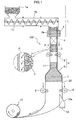
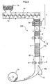
- Fig. 1 is a schematic view showing an example of tubular resin film manufacturing apparatus 100 according to this invention.
- the tubular resin film manufacturing apparatus 100 has a heating extruder 1 and a core unit 2.
- a thermoplastic resin is fed into the heating extruder 1 from a hopper 1a.
- the thermoplastic resin fed is heated and melted as it moves inside a barrel 1b.
- the thermoplastic resin is a resin tending to be oxidized at this time, it is preferable to replace with an inert gas, or degas, the interior of the barrel 1b as necessary.
- the heating extruder 1, preferably, has an adjustable resin extrusion output, and may have a pressure regulating mechanism (not shown) for adjusting a molten resin extruding pressure.
- the heating extruder 1 has a nozzle 3 for extruding the molten thermoplastic resin in a tubular form.
- the nozzle 3 is an element attached in the forward end of the heating extruder 1 for extruding the thermoplastic resin directly.
- the nozzle 3 may be integrated with the heating extruder 1.
- the nozzle 3 has a channel 3a having a ring-shaped section for passage of the molten resin. This channel 3a is designed so that an amount of resin extrusion per unit area is uniform over the entire ring-shaped section.
- the channel 3a may have a diameter of about 300mm, for example.
- the channel walls should preferably be maintained as smooth as possible such as by polishing.
- the amount of extrusion of molten resin is variable under the influence of the temperature of the nozzle 3. It is therefore preferable to control precisely the temperature of the nozzle 3 with a temperature control device (not shown).
- the tubular resin film obtained by this invention may be oriented simultaneously with extrusion by adjusting the temperature of the nozzle 3 between glass transition temperature (Tg)+20°C and glass transition temperature (Tg)+80°C.
- the temperature of the nozzle 3 When the temperature of the nozzle 3 is lower than (Tg)+20°C, the viscosity of the resin will increase, which makes a later film-forming process difficult. When the temperature of the nozzle 3 is higher than (Tg)+80°C, on the other hand, the orientation will become difficult by relaxation of the molecules forming the resin.
- a more desirable range of the temperature of the nozzle 3 is from (Tg)+30°C to glass transition temperature (Tg)+50°C.
- the nozzle 3 is designed such that, where the width of the channel 3a of the nozzle 3 is d, the relationship between the channel width d and thickness t of the extruded thermoplastic resin satisfies the following equations (1): t ⁇ d ⁇ 20 ⁇ t
- equations (1) t ⁇ d ⁇ 20 ⁇ t
- nozzle 3 is connected to a plurality of heating extruders so that two or more types of resin may join in the nozzle 3, it is also possible to manufacture a tubular resin film having a multilayer structure.
- the core unit 2 is disposed to oppose to the inner surface of the thermoplastic resin extruded in a tubular form from the nozzle 3 of the heating extruder 1, to shape the thermoplastic resin to a tubular resin film 20.
- the core unit 2 is connected to a gas source (not shown) and, as shown in an enlarged circle P in Fig. 1 , a gas can exude from the surface of the core unit 2 to the inner surface of the thermoplastic resin in order to reduce a friction occurring from a contact between the thermoplastic resin and the core unit 2 in time of molding.
- the temperature and amount of the gas exuding from the surface of the core unit 2 can be adjusted according to the type of thermoplastic resin. This may be achieved by a temperature control device and a pressure regulating device not shown.
- the surface of the core unit 2 is fluorine-coated, for example, to avoid an excessive friction when it should contact the thermoplastic resin in time of molding.
- a stabilizing device 4 is disposed between the nozzle 3 of the heating extruder 1 and the core unit 2 for stabilizing the shape of the thermoplastic resin extruded in a tubular form.
- the thermoplastic resin immediately after being extruded in a tubular form from the nozzle 3 of the heating extruder 1 is in a state of being maintained at a temperature considerably higher than the glass transition temperature (Tg), and the thickness of which rapidly changes from that of the channel width of the nozzle to a predetermined thickness, and thus in an unstable state easily influenced by a slight change of tension, turbulence of surrounding gas flow and so on.
- the stabilizing device 4 functions to stabilize the shape of the thermoplastic resin in such an unstable state in a way not to obstruct the flow of the resin.
- the tubular resin film formed subsequently may be free from creases, slacks, lenticulations and the like, and may have a small, uniform thickness and smooth surfaces.
- the stabilizing device 4 forms the most characteristic construction in this invention. In order to facilitate understanding, some examples of the stabilizing device 4 will be described below with reference to the drawings.
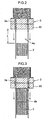
- Fig. 2 is a schematic view showing an example of construction in which the stabilizing device is in the form of a spacing portion 4a formed between the nozzle 3 of the heating extruder 1 and the core unit 2.
- the thermoplastic resin immediately after being extruded in a tubular form from the nozzle 3 of the heating extruder 1 remains at a temperature considerably higher than the glass transition temperature (Tg), as noted above.
- the spacing portion 4a prevents, for example, an external force due to a contact with a different object, and disturbances of atmosphere around the film such as non-uniform flows and temperature unevenness of the gas, from acting on the thermoplastic resin immediately after being extruded in a tubular form from the nozzle 3, thereby leading essentially unstable areas where the thickness decreases rapidly to a stabilized state.
- the tubular resin film formed subsequently may be free from creases, slacks, lenticulations and the like, and may have a small, uniform thickness and smooth surfaces.
- the size L of the spacing portion 4a shown in Fig. 2 (distance from the nozzle 3 to the core unit 2) can be set to 3 to 50mm, for example.
- the thermoplastic resin with its shape stabilized is subsequently forwarded to the core unit 2, and molded to the tubular resin film 20.
- Fig. 3 is a schematic view showing an example of construction in which the stabilizing device 4 is in the form of a second core unit 4b for exuding a gas from its surface.
- the second core unit 4b is connected to the gas source (not shown) as is the core unit 2.
- the temperature and amount of the gas exuding from the surface of the second core unit 4b can be adjusted according to the type of thermoplastic resin. This may be achieved by a temperature control device and a pressure regulating device not shown.
- the second core unit 4b is formed so that a gas exuding state from its surface is different from the gas exudation state from the surface of the core unit 2.
- the amount of gas exudation from the second core unit 4b is less than the amount of gas exudation from the core unit 2. Since the thermoplastic resin immediately after being extruded in a tubular form from the nozzle 3 of the heating extruder 1 remains at a temperature considerably higher than the glass transition temperature (Tg), an excessive amount of gas exudation from the second core unit 4b could roughen the inner surface of the thermoplastic resin, which is not desirable.
- Tg glass transition temperature
- the second core unit exudes the gas more gently than the core unit to the thermoplastic resin immediately after being extruded in the tubular form from the nozzle 3, in order to maintain a non-contact state, and to realize a predetermined cooling condition while avoiding changes in the shape of the inner surface of the thermoplastic resin, thereby stabilizing the shape of the thermoplastic resin.
- the tubular resin film formed subsequently may be free from creases, slacks, lenticulations and the like, and may have a small, uniform thickness and smooth surfaces.
- the second core unit 4b may be used in combination with the spacing portion 4a described above.
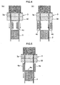
- Figs. 4 (a) and (b) are schematic views showing two examples the stabilizing device 4 in the form of a temperature control mechanism.
- the temperature control mechanism is in the form of a temperature control heater 4c for controlling, from inside the tube, the temperature of the thermoplastic resin extruded in the tubular form.
- the temperature control mechanism is in the form of a temperature control heater 4d for controlling, from outside the tube, the temperature of the thermoplastic resin extruded in the tubular form.
- the temperature control heaters 4c and 4d are operable under PID control, for example, to cool the thermoplastic resin gradually to a temperature close to Tg.
- the temperature control mechanism carries out, for example, actively a temperature control, as opposed to natural cooling, of the thermoplastic resin thereby to stabilize the shape of the thermoplastic resin.
- the tubular resin film formed subsequently may be free from creases, slacks, lenticulations and the like, and may have a small, uniform thickness and smooth surfaces.
- the temperature control mechanism may be a combination of what is shown in Fig. 4 (a) and Fig. 4 (b) , which is a construction having the temperature control heaters arranged both inside and outside the thermoplastic resin extruded in the tubular form. Or the temperature control heater(s) may be used in combination with the spacing portion 4a and/or the second core unit 4b described hereinbefore.
- Fig. 5 is a schematic view showing an example of construction in which the stabilizing device 4 is in the form of a gas flow preventive mechanism 4e.
- the gas flow preventive mechanism 4e may be constructed as barrier walls, for example, that prevent gas flow blowing to the thermoplastic resin extruded in the tubular form from the nozzle 3.
- the gas flow preventive mechanism 4e prevents gas flow extruding from the core unit 2 inside the tube, and gas flow outside the tube, from blowing to the thermoplastic resin extruded in the tubular form from the nozzle 3.
- the tubular resin film formed subsequently may be free from creases, slacks, lenticulations and the like, and may have a small, uniform thickness and smooth surfaces.
- the gas flow preventive mechanism 4e may be used in combination with the spacing portion 4a, the second core unit 4b and/or the temperature control mechanism described hereinbefore.
- the nozzle 3 of the heating extruder 1 has at least an edge 3b thereof formed of a superhard material.
- the edge 3b herein refers to a fore-end of a discharge exit of the nozzle 3 for discharging the thermoplastic resin.
- Fig. 6 is (a) a perspective view and (b) a sectional view of the nozzle 3, and (c) an enlarged sectional view of the edge 3b.
- edge 3b of the nozzle 3 In order to improve peeling of the thermoplastic resin from the nozzle 3, it is usually necessary to process the edge 3b of the nozzle 3 sharply. Specifically, in Fig. 6 (c) , it is preferred that corner radii R1 and R2 are set to 50 ⁇ 5 ⁇ m or less. With this shape, the thermoplastic resin extruded from the nozzle 3 does not adhere to the edge 3b, whereby a film having flat and smooth surfaces may be produced. However, the sharper the edge 3b is shaped, the less strong the edge 3b generally becomes. This gives rise to a problem of the edge 3b being gradually worn by maintenance and the like, and in the worst case, the edge 3b being chipped.
- the edge 3b of the nozzle 3 is formed of a superhard material, so that it is possible to process it to a sharper shape and give it sufficient durability. Consequently, the edge is never worn out or chipped owing to the pressure of extruding the thermoplastic resin, and the thermoplastic resin may be extruded stably and continuously for a long time.
- Rockwell A hardness of the superhard material for forming the nozzle 3, preferably, is 85 or higher.
- the superhard material may be a titanium alloy or ceramic material, for example.
- the surfaces of the superhard material may be plated or given nitriding treatment.
- a suitable nozzle head When extruding the molten resin from the nozzle 3, a suitable nozzle head may be attached to the nozzle 3. Then, the molten resin is extruded from the nozzle 3 through the nozzle head.
- An example of nozzle head usually employed is a parallel nozzle 30 having a channel extending straight to the exit as shown in Fig. 6 (b) .
- a diameter enlarging nozzle 31 as shown in Fig. 7 (a) may be used as necessary. The diameter enlarging nozzle 31 extrudes the thermoplastic resin as expanded radially, and thus the extruded thermoplastic resin has an enlarged diameter.
- thermoplastic resin When the thermoplastic resin is extruded from the nozzle with such diameter enlarging nozzle 31, a force may be applied to the excluded resin to enlarge the diameter thereof.
- a force may be applied to the excluded resin to enlarge the diameter thereof.
- a diameter enlarged nozzle 32 as shown in Fig. 7 (b) may be used in which the channel 3a has a diameter reduced once and then enlarged. With this shape, the diameter of extrusion of the thermoplastic resin may be reduced, to realize a compact construction of the entire apparatus.
- the molten resin is forward from the barrel 1b to the nozzle 3 of the heating extruder 1 in the following two main modes. They are a spider mode that extrudes the molten resin in an ordinary way using a single channel, and a spiral mode that once branches the molten resin, for example, by four spiral-shaped channels arranged at an end of the barrel 1b, and joins again the branched molten resin. While whichever mode may be used in this invention, the latter spiral mode is preferred since the tubular resin film 20 formed subsequently has a beautiful appearance without resin flow pattern on the surface. Where a filter is disposed between the barrel 1b and nozzle 3 from of the heating extruder 1, impurities may be removed from the molten resin, to obtain a further enhanced appearance.
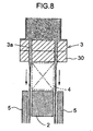
- the tubular resin film manufacturing apparatus 100 may include an outside unit 5 opposed to the outer surface of the thermoplastic resin extruded in the tubular form from the heating extruder 1.
- Fig. 8 is an enlarged fragmentary view of the tubular resin film manufacturing apparatus 100 having the outside unit 5.
- the outside unit 5 is provided for the tubular resin film manufacturing apparatus 100, this outside unit 5 cooperates with the core unit 2 to shape, from both outside and inside, the thermoplastic resin extruded in the tubular form from the nozzle 3.
- the tubular resin film 20 may be manufactured which is molded more accurately and excellent in smoothness.
- the outside unit 5 may be constructed to exude gas from part or whole of its surface. In this case, it is possible to adjust the temperature of the exuding gas.
- the outer surface of the thermoplastic resin and the outside unit 5 may be maintained out of contact with each other.
- the tubular resin film formed subsequently may be free from creases, slacks, lenticulations and the like, and may have a small, uniform thickness and smooth surfaces.
- the core unit 2, second core unit 4b and outside unit 5 described above may be formed of a porous material, respectively.
- the gas may be exuded uniformly from the entire surface of each member, with little local variations in the amount of gas exudation. Consequently, the non-contact between the thermoplastic resin and the core units is further promoted, thereby minimizing the possibility of leaving scratches and line patterns on the tubular resin film formed subsequently. This assures a high-quality film having smooth and flat surfaces.
- the porous material includes a metallic porous material (such as porous sintered metal), an inorganic porous material (porous ceramics), a filter material and a metal formed with numerous bores.
- a metal porous material is preferred and a porous sintered metal is the most desirable.
- the porous material has the pore size, thickness and so on adjusted to realize a uniform gas exudation state.
- a mechanism and method for stretching the tubular resin film will be described in detail below, referring to Fig. 1 again.
- the film stretching mechanism and method described hereinafter can use the tubular resin film manufactured by the tubular resin film manufacturing apparatus according to this invention, but can be applied also to the case of stretching a tubular resin film separately manufactured beforehand (which is not limited to what is manufactured by the tubular resin film manufacturing apparatus according to this invention).
- the tubular resin film manufacturing apparatus 100 includes a stretching section 6 for stretching the tubular resin film 20 molded by the core unit 2, and a maintaining section 7 for maintaining the shape of the stretched tubular resin film 20.
- a preheating section 11 may be provided at an upstream stage of the stretching section for preheating the tubular resin film 20.
- the preheating section 11 may be formed of a porous material as is the core unit 2, for example, and connected to the gas source not shown to exude gas flow having undergone an appropriate temperature control from the surface of the preheating section 11 to the inner surface of the tubular resin film 20.
- the tubular resin film 20 may be preheated to a variable preheat temperature.
- the stretching temperature of the tubular resin film 20 preferably, is in a range of Tg to Tg+50(°C).
- a more desirable temperature range is a range of Tg+10(°C) to Tg+30(°C). With such a range, the tubular resin film 20 may be oriented efficiently, and a retardation may be developed significantly.
- the stretching temperature is lower than Tg, a strong stress must be applied to the film in order to stretch it, resulting in a possibility of breaking the film.
- the stretching temperature is higher than the upper limit, the resin will become close to a molten state in most cases. Even if stretched, the molecules cannot be oriented and development of a retardation cannot be expected.
- the stretching section 6 and maintaining section 7 form a most characteristic construction in this invention. In order to facilitate understanding, the stretching section 6 and maintaining section 7 will particularly be described hereinafter.
- the stretching section 6 includes drawing rollers 8 for stretching the tubular resin film 20 mainly in the longitudinal direction (MD stretch), and preferably a diameter enlarging mandrel 9 for stretching the film mainly in the circumferential direction (TD stretch).
- a tubular resin film manufacturing apparatus 200 shown in Fig. 9 may be used.
- the tubular resin film manufacturing apparatus 200 employs a cylindrical mandrel 10 having the same sectional shape as the core unit 2, instead of the conical mandrel 9 in the tubular resin film manufacturing apparatus 100 of Fig. 1 .
- a contraction in the TD direction may be suppressed in time of MD stretch.
- the drawing rollers 8 forming the stretching section 6 may be disposed in at least one location, but, preferably, disposed in two locations at a suitable interval along the longitudinal direction of the tubular resin film 20 as shown in Figs. 1 and 9 .
- the MD stretch may be carried out more accurately and easily by a difference in rotating speed between the two drawing rollers 8.
- the drawing rollers 8 are arranged on both the outer surface and inner surface of the tubular resin film 20 to pinch the tubular resin film 20 between both drawing rollers.
- a tubular resin film suitable as a retardation film to be used for liquid crystal displays (LCDs) and the like is free from creases, slacks, lenticulations and the like, and has a small, uniform thickness and smooth surfaces, thus realizing a high-quality resin film product with little retardation variations.
- the tubular resin film 20 When the TD stretch is performed, as shown in Fig. 1 , the tubular resin film 20 may be fitted to follow the surface of the conical mandrel 9, and the tubular resin film 20 may be downward in this state. As the tubular resin film 20 is transported, the TD stretch of the tubular resin film 20 is performed with a draw ratio determined by the outside diameter of the mandrel.
- the conical mandrel 9 may be made dividable into a plurality of parts, with each part radially movable, to render the enlarged diameter of the tubular resin film variable.
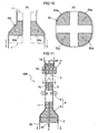
- Fig. 10 shows an example of such a split type diameter enlarging mandrel 50.
- the split type diameter enlarging mandrel 50 shown in Fig. 10 has a construction dividable into four mandrel pieces (50a-50d). Each of the mandrel pieces (50a-50d) can be moved radially. The movements may be performed manually or by a mechanical device such as an electric motor.
- Each mandrel piece (50a-50d) can be moved not only in time of an off-line state not working on the tubular resin film, but also during a stretching process.
- the tubular resin film of this invention can be made a high-quality resin film product.
- the preheating section 11 and maintaining section 7 may also be constructed to carry out similar operations in accordance with the split and movement of the split type diameter enlarging mandrel 50.
- an orientation may be applied circumferentially of the film, thereby to manufacture a tubular resin film suitable as a retardation film to be used for liquid crystal displays (LCDs) and the like.
- a tubular resin film is free from creases, slacks, lenticulations and the like, and has a small, uniform thickness and smooth surfaces, thus realizing a high-quality resin film product with little retardation variations.
- the conical mandrel 9 and drawing rollers 8 may be used simultaneously.
- Draw ratios of the tubular resin film 20 in the MD stretch direction and TD stretch direction may be set to desired values by selecting a rotating speed of the drawing rollers 8 and an outside diameter of the conical mandrel 9.
- the MD stretch and TD stretch may be performed separately from each other.
- the MD stretch may first be carried out with the drawing rollers 8, and then the TD stretch carried out by applying the tubular resin film to the conical mandrel 9.
- the TD stretch may first be carried out by applying the tubular resin film to the conical mandrel 9, and the TD-stretched tubular resin film may be MD-stretched with the drawing roller 8.
- the drawing rollers 8 forming the stretching section 6 and directly contacting the surface of the tubular resin film 20, preferably, are formed of a flexible material (e.g. silicone rubber) that does not damage the surface. It is preferable to arrange the drawing rollers 8 to contact at a plurality of equidistant points around the tubular resin film 20, so that the tubular resin film 20 may be stretched uniformly.
- the conical mandrel 9 and/or cylindrical mandrel 10 forming the stretching section 6, preferably, are/is formed of a porous material such as a porous sintered metal, as are the core unit 2, second core unit 4b and outside unit 5 described hereinbefore.
- Each mandrel may be connected to the gas source (not shown) to exude the gas at an appropriately adjusted temperature and flow rate from the surface, as necessary. Then a direct contact between the tubular resin film 20 and the mandrel is avoided to eliminate the possibility of leaving scratches and line patterns on the inner surface of the tubular resin film. This assures a high-quality film having smooth and flat surfaces.
- the non-contact between the tubular thermoplastic resin and the stretching section is promoted to reduce resistance in time of stretching. This provides an effect of a smooth stretching process being carried out by the stretching section.
- the maintaining section 7 is provided to maintain the shape of the stretched tubular resin film 20.
- the tubular resin film may contract by reaction. Without the maintaining section, the stretched and oriented film will contract in a free state, resulting in thickness variations and retardation variations.
- the maintaining section 7 maintains and fixes the shape of the stretched tubular resin film 20 to prevent contraction and the like of the stretched film. According to this invention, therefore, the tubular resin film having passed through the maintaining section 7 is free from creases, slacks, lenticulations and the like, and has a small, uniform thickness and smooth surfaces, thus realizing a high-quality resin film product with little retardation variations.
- the maintaining section 7 is constructed to cool the tubular resin film. It is also preferable that the cooling temperature in the maintaining section and the length of the maintaining section are adjusted so that the film temperature will be a temperature not exceeding Tg by the time the film has passed through the maintaining section.
- the maintaining section 7 is formed of a porous material as is the above stretching section 6, and is connected to the gas source (not shown) to exude the gas at an appropriately adjusted temperature and flow rate, as necessary, from the surface of the maintaining section 7 to the inner surface of the stretched tubular resin film 20.
- the preheating section 11, the conical mandrel 9 or cylindrical mandrel 10 forming the stretching section 6, and the maintaining section 7, are shown as arranged inside the cylindrical resin film 20. They may be arranged inside and outside the cylindrical resin film 20 to hold the cylindrical resin film 20 from both sides. In this case, the cylindrical resin film 20 is not completely exposed, and may be stretched in a state of increased stability.
- the tubular resin film 20 obtained in this way has very smooth surface though small in thickness, may be given a still better orientation, and therefore can conveniently be used as a retardation film for liquid crystal displays (LCDs) and the like.
- thickness of the film used as such a retardation film may have an arbitrary value, it is desirable that the film is made as thin as possible to achieve a cost reduction or thinning of a device that uses the retardation film as a component thereof.
- the gas exuding from the surfaces of the core unit 2, second core unit 4b, preheating section 11, stretching section 6 and maintaining section 7 could flow into the region of the stabilizing device 4 between the nozzle and core unit, thereby causing an unexpected pressure increase in the region of stabilizing device 4 or unexpectedly raising the internal pressure in the tubular resin film 20.
- the thermoplastic resin is inflated outward, or repeats contraction and expansion.
- Such a phenomenon is not desirable since it could have an adverse effect on the surface smoothness and thickness uniformity of the film ultimately obtained.
- a venting device 14 may be provided to extend from the nozzle 3 through the heating extruder 1 for communication with ambient air, and a venting device 16 penetrating the core unit 2 and second core unit and a venting device 15 penetrating the maintaining section 7 and stretching section 6 (or preheating section 11) may be provided to place the interior of the tubular resin film 20 in communication with ambient air.
- venting devices may be used independently or may be used together.
- An internal pressure adjusting mechanism such as an internal pressure regulating valve may be provided.
- the venting device 14 since the gas flow out through the venting device 14, a turbulence of gas flow may occur in the region of the stabilizing device 4 between the core unit and the nozzle, which could have an adverse effect on the surface smoothness and thickness uniformity of the film ultimately obtained. Therefore, care must be taken to prevent the turbulence of gas flow from influencing the film.
- the venting device 14 is provided, for example, it is preferable to extend piping from the venting device 14 downward to a predetermined position (e.g.
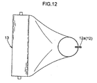
- the tubular resin film 20 with the shape fixed thoroughly is transported to a position of a cutting device 12 where it is cut open in the longitudinal direction to become a flat, long sheet-like film (see Fig. 1 ).
- the cutting device 12 is arranged, for example, to have a cutting portion 12a opposed to the transporting direction of the tubular resin film 20. As the tubular resin film 20 is transported downward, the cutting device 12 can cut open the tubular resin film 20.
- Fig. 12 is a bottom view of the tubular resin film manufacturing apparatus 100, showing a state of the tubular resin film being cut open by the cutting device 12. As seen from Fig. 12 , the cutting device 12 may just be fixed to an arbitrary position intersecting the tubular resin film 20.
- the cutting device 12 may also be constructed revolvable circumferentially of the tubular resin film 20.
- the cutting portion 12a has its direction changeable with revolution of the cutting device 12, it can cut the tubular resin film 20 to a spiral shape in cooperation with the downward transport of the tubular resin film 20. Further, a spiral cut of desired pitch can be performed by appropriately adjusting the transport speed of the tubular resin film 20 and revolving speed of the cutting device 12.
- a laser cutter is used as the cutting device 12, a laser emitting direction may be changed by changing, by remote control or otherwise, the direction of a prism through which the laser passes. Thus, without moving the laser cutter directly, a spiral cut of the tubular resin film 20 may be performed easily.
- the laser cutter may be installed in any selected location regardless of the transport direction of the tubular resin film 20, which greatly improves the degree of freedom of apparatus design. With such a laser cutter, not only a spiral cut but a still more complicated cut can also be performed, to increase application of the resin film greatly. While the method of revolving the cutting device 12 circumferentially of the tubular resin film 20 has been described above, a similar film cut to a spiral shape can be obtained also by rotating a portion including the nozzle, with the cutting device 12 fixed. With such a construction, there is no need to revolve a winding device described hereinafter, to achieve space-saving.
- Fig. 13 is a schematic view showing part of a tubular resin film manufacturing apparatus having the two cutting devices 12, and (b) is a bottom view of the tubular resin film manufacturing apparatus in (a).
- an insert unit 60 having substantially the same outside diameter as the inside diameter of the tubular resin film 20 may be placed inside the tubular resin film 20 in advance.
- this insert unit 60 is formed of a porous material and connected to the gas supply source, not shown, to exude the gas from the surface of the insert unit 60, the insert unit and the inner surface of the tubular resin film 20 may be maintained out of contact with each other, to reduce the possibility of damage, which is desirable.
- the tubular resin film 20 is cut in the longitudinal direction into a sheet-like film.
- Two sheet-like films may be obtained, of course, by a conventional method, that is a method of folding the tubular resin film 20 and cutting off the opposite ends.
- the long sheet-like film formed by the cutting action of the cutting device 12 is ultimately taken up by a winding device 13 (see Fig. 1 or 13 ).
- the winding device 13 needs to be interlocked to the above cutting device 12 so that the film is not twisted in time of take-up. That is, where the cutting device 12 is fixed, the winding device 13 is also fixed. Where the cutting device 12 makes a revolving movement, the winding device 13 must also make a revolving movement accordingly. Where the winding device 13 and cutting device 12 are integrated, the cut tubular resin film 20 is taken up as it is, thus capable of coping with any one of the above cases.
- An elongated paper tube may be cited as an example of the part of the winding device 13.
- the sheet-like film obtained from the tubular resin film of this invention produced as described above can be given an excellent orientation, and may therefore conveniently be used as a retardation film.
- the retardation film is used in liquid crystal display device using TN, VA, or STN mode, in order to improve lowering of the viewing angle by birefringence of the liquid crystal.
- the retardation film will cause an irregular color of the liquid crystal display when variations in the slow axis angle exceed ⁇ 3 degrees.
- the sheet-like film obtained by this invention has variations in the slow axis angle within ⁇ 3 degrees in the width direction, which indicates excellent display quality.
- a retardation film manufactured by stretching of the conventional tentering mode only the film central part could be used because of large variations in the slow axis angle in end regions.
- the entire width of the film may be used. For this reason, yield is improved, and manufacturing cost may be reduced substantially.
- thermoplastic resin usable in this invention examples include polyethylene, polypropylene, polystyrene, polycarbonate, polyester, polyarylate, polyamide, cyclic polyolefin, ethylene vinyl alcohol copolymer, and polyethersulfone. These resins may be used alone, or a polymer blend or copolymer containing two or more of these may be used. Or derivatives or conversions of these resins may be used.
- thermoplastic resin film obtained from the tubular resin film of this invention is used as a retardation film for the above liquid crystal displays (LCDs) or the like in particular
- the resin material a material that can secure high dimensional stability (e.g. thickness uniformity) and optical stability (e.g. retardation uniformity) without being influenced by heat and/or moisture, a material that has a high glass transition temperature (Tg) (e.g. 120°C or higher) to withstand heat from the backlight of the liquid crystal display, or a material excellent in visible light transmittance to provide an excellent liquid crystal display.
- Tg glass transition temperature
- the thermoplastic resin film may be unstretched, or may be uniaxially or biaxially stretched.
- the thermoplastic resin film may be oriented by coating it with a discotic liquid crystal polymer or nematic liquid crystal polymer.
- the retardation film is required to have long-term stability. To meet this, it is preferred that the absolute value of the photoelastic coefficient of the film does not exceed 1.0 ⁇ 10 -11 Pa -1 . It is particularly preferable to use, as a thermoplastic resin that satisfies such a characteristic, a norbornene polymer which is cyclic polyolefin.
- the norbornene includes a homopolymer consisting of a norbornene monomer or its hydrogenation, and a copolymer of a norbornene monomer and a vinyl compound or its hydrogenation.
- the thermoplastic resin may have a small amount of additive such as antioxidant, lubricant, colorant, dye, pigment, inorganic filler and/or coupling agent added thereto in a range that does not affect the physical properties (glass transition temperature, light transmittance and so on).
- additive such as antioxidant, lubricant, colorant, dye, pigment, inorganic filler and/or coupling agent added thereto in a range that does not affect the physical properties (glass transition temperature, light transmittance and so on).
- antioxidant examples include a phenolic antioxidant, phosphoric acid antioxidant, sulfuric antioxidant, lactonic antioxidant, and hindered aminic light stabilizer (HALS).
- HALS hindered aminic light stabilizer
- a resin such as cyclic polyolefin
- a phenolic antioxidant may be used suitably, taking thermal stability and compatibility into consideration.
- phenolic antioxidant include pentaerythritol tetrakis [3-(3, 5-di-t-butyl-4-hydroxy phenyl) propionate] (e.g. trade name "IRGANOX 1010" (made by Ciba Specialty Chemicals)), Octadecyl-3-(3, 5-di-t-butyl-4-hydroxy phenyl) propionate (e.g.
- IRGANOX 1076 made by Ciba Specialty Chemicals
- 3, 3', 3", 5, 5', 5"-hexa-t-butyl-a, a', a"-(mesitylene 2, 4, 6, -trier) tri-p-cresol e.g. trade name "IRGANOX 1330” (made by Ciba Specialty Chemicals)
- 1, 3, 5-tris (3, 5-di-t-butyl-4-hydroxybenzyl)-1, 3, 5-triazine-2, 4, 6(1H, 3H, 5H)-trione e.g.
- thermoplastic resin of the antioxidant preferably, is adjusted to a range of 0.01 to 5% by weight. The content exceeding 5% by weight will impair light transmittance and mechanical strength of the film, and that less than 0.01% by weight will fail to secure a sufficient antioxidant effect, which is not desirable.
- lubricant examples include a lubricant of fatty acid amide series, a lubricant of the nonionic surface active agent type, a hydrocarbon lubricant, a fatty acid lubricant, an ester lubricant, an alcoholic lubricant, a fatty acid metal salt lubricant (metal soap), a montanic acid ester partial saponification, and a silicone lubricant.
- a lubricant of fatty acid amide series may be use suitably, taking thermal stability and compatibility into consideration.
- lubricant of fatty acid amide series include stearic acid amide (e.g.
- DIAMID 200 (made by Nippon Kasei Chemical Co., Ltd.)), methylene bis stearic acid amide (e.g. trade name "BISAMID LA” (made by Nippon Kasei Chemical Co., Ltd.)), m-xylylene bis stearic acid amide (e.g. trade name "SLIPAX PXS” (made by Nippon Kasei Chemical Co., Ltd.)), ethylene bis stearic acid amide (e.g. trade name "Kao Wax EB” (made by Kao Corp.), and ARMO WAX EBS (made by Lion Akzo Co., Ltd.).
- the content in the thermoplastic resin of the lubricant preferably, is in a range of 0.01 to 10% by weight, and most preferably 0.05 to 1% by weight.
- the content less than 0.01% by weight will hardly produce effects of reducing extruding torque, or preventing scratches inflicted on the film.
- the content exceeding 10% by weight will increase the chance of slippage with the extruder screw, which makes a uniform feeding of the resin impossible and a stable manufacture of the film difficult. Further, the amount of bleed-out increases with time, causing poor appearance of the film and poor adhesion.
- phenolic antioxidants, lubricants and the like may be used alone or may be used in combination of two or more of these.
- Methods of adding the additives such as antioxidant and lubricant to the thermoplastic resin include a method in which pellets of the thermoplastic resin and a predetermined quantity of powder of the additives are mixed, and heat-melted by a heating extruder, a method in which the thermoplastic resin and additives are dissolved in an organic solvent which is then separated, a method in which a masterbatch of the thermoplastic resin and additives is prepared beforehand, and a method in which the above masterbatch is mixed with the same type or a different type of resin as/to the resin used in preparing the masterbatch.
- a heating extruder of the spiral mode having a mesh type filter (mesh size: 10 ⁇ m) was used.
- a nozzle having a parallel nozzle was used.
- a metal cylinder was provided in the tube interior of the resin to act as the stabilizing device.
- a metallic porous material having a 35 ⁇ m average pore size was used.
- a preheating section formed of a porous material was provided inside and outside the tubular resin film.
- a diameter enlarging mandrel formed of a porous material with a vertical diameter ratio of 1:1.4, and multipoint drawing rollers with a vertical velocity ratio of 1:1.2 were used.
- time of stretching MD stretch and TD stretch were performed simultaneously while temperature control was carried out from inside and outside the film.
- a maintaining section formed of a porous material and having the same diameter as the lower end of the above diameter enlarging mandrel was provided inside the tubular resin film.
- the venting device 15 was provided to extend through the preheating section, the diameter enlarging mandrel forming the stretching section, and the maintaining section.
- the tubular resin film obtained as described above was cut open with two cutters as shown in Fig. 13 , and two sheet-like films with a width of about 650mm were taken up.
- the sheet-like films had excellent outward appearance, with thickness variations and retardation variations both at ⁇ 2% or less, slow axis variations also at ⁇ 2 degrees or less.
- This embodiment shows an example using a film raw material and a stabilizing device different from those in the above Embodiment 1.
- the film producing conditions in this embodiment are the same as the conditions in the above Embodiment 1 except for the following points.
- a second core unit formed of a porous material was provided in the tube interior of the resin.
- Preheating section temperature and final film temperature in the preheating section were set to 150°C.
- MD stretch and TD stretch were performed separately while carrying out temperature control from inside and outside the film.
- Stretching section temperature was set to 150°C both inside and outside.
- the length of the stretching section was adjusted to a length capable of maintaining the film temperature at 150°C.
- a maintaining section formed of a porous material having a diameter 2mm smaller than that at the lower end of the above diameter enlarging mandrel was provided inside the tubular resin film.
- the venting device 14 was provided to extend from the nozzle 3 through the heating extruder 1, and so was the venting device 15 to extend through the preheating section, the diameter enlarging mandrel forming the stretching section, and the maintaining section.
- the tubular resin film obtained as described above was cut open with one cutter as shown in Fig. 12 , and one sheet-like film with a width of about 1300mm was taken up.
- the sheet-like film had excellent outward appearance, with thickness variations and retardation variations both at ⁇ 2% or less, slow axis variations also at ⁇ 2 degrees or less.
- This embodiment also shows an example using a film raw material and a stabilizing device different from those in the above Embodiment 1.
- IRGANOX 1010 made by Ciba Specialty Chemicals
- the film producing conditions in this embodiment also are the same as the conditions in the above Embodiment 1 except for the following points.
- Temperature control heaters were provided in the tube interior and tube exterior of the resin to act as the stabilizing device.
- the temperature control heaters temperature-adjusted to an extent that thickness variations do not occur to the thermoplastic resin extruded in the tubular form.
- MD stretch and TD stretch were performed separately while carrying out temperature control from inside and outside the film.
- the venting device 14 was provided to extend from the nozzle 3 through the heating extruder 1.
- a pipe extends from the venting device 14 to an area above the preheating section upper, so that the gas exuding from the preheating section, stretching section and maintaining section escapes directly through the venting device 14 without influencing the region of the stabilizing device 4.
- the tubular resin film obtained as described above was cut open with two cutters as shown in Fig. 13 , and two sheet-like films with a width of about 650mm were taken up.
- the sheet-like films had excellent outward appearance, with thickness variations and retardation variations both at ⁇ 2% or less, slow axis variations also at ⁇ 2 degrees or less.
- This embodiment shows an example of making a film by using a split type diameter enlarging mandrel as shown in Fig. 10 .
- a split type diameter enlarging mandrel as shown in Fig. 10 , which is formed of a porous material with a vertical diameter ratio of 1:1.4, and multipoint drawing rollers with a vertical velocity ratio of 1:1.2, were used.
- the split type diameter enlarging mandrel was divided and expanded so that the draw ratio in the radial direction increases to 1.5 times.
- time of stretching MD stretch and TD stretch were performed simultaneously while temperature control was carried out from inside and outside the film.
- a maintaining section formed of a porous material and having the same diameter as the lower end of the above split type diameter enlarging mandrel was provided inside the tubular resin film.
- a maintaining section formed of a different type of porous material is provided outside.
- the tubular resin film obtained as described above was cut open with two cutters as shown in Fig. 13 , and two sheet-like films with a width of about 650mm were taken up.
- the sheet-like films had excellent outward appearance, with thickness variations and retardation variations both at ⁇ 2% or less, slow axis variations also at ⁇ 2 degrees or less.
- This embodiment shows an example of longitudinally stretching the film using the film manufacturing apparatus shown in Fig. 9 .
- the molten resin film discharged from the die was cooled to 180°C by air flowing at 25°C and at a flow rate of 50L/min. from an air cooling device (core unit and outside unit) having a 1mm gap and installed inside and outside the cylindrical film in a position at a 20mm distance from the die nozzle, and was then led to a four-point support type first drawing device having movable rolls inside the film, and speed-adjustable rolls outside the film, to be drawn at a rate of 5m/min.
- an air cooling device core unit and outside unit
- the cylindrical film was reheated in a heating furnace (preheating section) having an atmospheric temperature adjusted to 175°C, and was drawn at a speed difference of 1.3 times by a second drawing device having the same function as the first drawing device, to be stretched to be 1.3 times in the longitudinal direction.
- a heating furnace heating section
- the interior is formed of a stretching section and maintaining section using a porous material.
- the film was cut open by a cutter disposed outside the film and parallel to the direction of flow, and thereafter was opened to a planar shape along a transport guide made to cause no crease.
- planar film obtained was wound on a paper tube whose width was 600mm. Two planar films having a thickness of 0.1mm were obtained.
- the thickness of the films obtained was measured with a micrometer every 10mm in the width direction, which showed a good result that thickness accuracy in the width direction was ⁇ 2 ⁇ m.
- the retardation was measured, it showed a retardation film with a in-plane regardation having a value of 100nm.
- thickness variations and retardation variations were both ⁇ 2% or less.
- Slow axis variations were ⁇ 2 degrees or less. At this time, the slow axis of the retardation of the film had an angle parallel to the longitudinal direction of the film.
- the stretching method is different, compared with the producing conditions in the above Embodiment 5.
- the cylinder film drawn by a drawing device similar to the four-point support type first drawing device in the above Embodiment 5 is reheated in a heating furnace (preheating section) having an atmospheric temperature adjusted to 175°C.
- the film is then led to an inner mandrel disposed inside the film and divided circumferentially into four parts as shown in Fig. 10 , and having air outlets formed in outer walls thereof, to be stretched circumferentially by hot air at 175°C blow from inside, and a mechanical, radial expansion by 1.3 times of the mandrel body.
- the film is drawn at the rate of 5m/min. by the second drawing device disposed downstream of the cutter.
- the film is cut open by the cutter disposed outside the film and parallel to the direction of flow, and thereafter is opened to a planar shape along the transport guide made to cause no crease.
- the planar film obtained was wound on two paper tubes. Two planar films having a thickness of 0.1mm were obtained.
- the thickness of the films obtained was measured with a micrometer every 10mm in the width direction, which showed a good result that thickness accuracy in the width direction was ⁇ 2 ⁇ m.
- the retardation was measured, it showed a retardation film with a thickness retardation having a value of 100nm.
- thickness variations and retardation variations were both ⁇ 2% or less.
- Slow axis variations were ⁇ 2 degrees or less. At this time, the slow axis of the retardation of the film had an angle of 90 degrees to the longitudinal direction of the film.
- the cylinder film drawn by a drawing device similar to the four-point support type first drawing device in the above Embodiment 5 is reheated in a heating furnace (preheating section) having an atmospheric temperature adjusted to 175°C.
- the film is then led to the inner mandrel disposed inside the film and divided circumferentially into four parts, and having air outlets formed in outer walls thereof, to be stretched circumferentially by hot air at 175°C blow from inside, and a mechanical, radial expansion by 1.3 times of the mandrel body.
- the cylindrical film is drawn at a speed difference of 1.3 times by the second drawing device having the same function as the first drawing device, to be stretched to be 1.3 times in the longitudinal direction.
- the film is cut as in Embodiment 5, to obtain two planar films having a thickness of 0.1mm.
- the thickness of the films obtained was measured with a micrometer every 10mm in the width direction, which showed a good result that thickness accuracy in the width direction was ⁇ 2 ⁇ m.
- the retardation was measured, it showed a retardation film with an in-plane retardation and a retardation in the thickness direction both having a value of 100nm.
- thickness variations and retardation variations were both ⁇ 2% or less.
- Slow axis variations were ⁇ 2 degrees or less.
- the manufacturing apparatus and manufacturing method for tubular resin films according to this invention can be used for variety purposes, and can be used, for example, as a manufacturing apparatus and manufacturing method for retardation film, shrink film and laminate film.
Landscapes
- Engineering & Computer Science (AREA)
- Mechanical Engineering (AREA)
- Physics & Mathematics (AREA)
- Thermal Sciences (AREA)
- Manufacturing & Machinery (AREA)
- Shaping By String And By Release Of Stress In Plastics And The Like (AREA)
- Extrusion Moulding Of Plastics Or The Like (AREA)
Abstract
Applications Claiming Priority (11)
| Application Number | Priority Date | Filing Date | Title |
|---|---|---|---|
| JP2003024899 | 2003-01-31 | ||
| JP2003024899 | 2003-01-31 | ||
| JP2003023208 | 2003-01-31 | ||
| JP2003023208 | 2003-01-31 | ||
| JP2003050815 | 2003-02-27 | ||
| JP2003050815 | 2003-02-27 | ||
| JP2003090375 | 2003-03-28 | ||
| JP2003090375 | 2003-03-28 | ||
| JP2003331555 | 2003-09-24 | ||
| JP2003331555A JP3662912B2 (ja) | 2003-01-31 | 2003-09-24 | 管状樹脂フィルムの製造装置 |
| PCT/JP2003/016534 WO2004067266A1 (ja) | 2003-01-31 | 2003-12-24 | 管状樹脂フィルムの製造装置 |
Publications (3)
| Publication Number | Publication Date |
|---|---|
| EP1595686A1 EP1595686A1 (en) | 2005-11-16 |
| EP1595686A4 EP1595686A4 (en) | 2010-12-08 |
| EP1595686B1 true EP1595686B1 (en) | 2012-08-01 |
Family
ID=32831157
Family Applications (1)
| Application Number | Title | Priority Date | Filing Date |
|---|---|---|---|
| EP03786257A Expired - Lifetime EP1595686B1 (en) | 2003-01-31 | 2003-12-24 | Unit for production of tubular resin film |
Country Status (7)
| Country | Link |
|---|---|
| US (1) | US7625194B2 (ja) |
| EP (1) | EP1595686B1 (ja) |
| JP (1) | JP3662912B2 (ja) |
| KR (1) | KR101006419B1 (ja) |
| AU (1) | AU2003296075A1 (ja) |
| CA (1) | CA2514919C (ja) |
| WO (1) | WO2004067266A1 (ja) |
Families Citing this family (11)
| Publication number | Priority date | Publication date | Assignee | Title |
|---|---|---|---|---|
| JP3710800B2 (ja) * | 2003-01-31 | 2005-10-26 | 住友ベークライト株式会社 | 管状樹脂フィルムの製造装置および製造方法 |
| CN101107115B (zh) * | 2005-01-18 | 2011-09-14 | 住友电木株式会社 | 心轴,采用心轴的树脂膜制造装置及制造方法 |
| JP4008023B2 (ja) | 2005-09-05 | 2007-11-14 | 住友ベークライト株式会社 | 管状樹脂フィルムの切断巻取り装置および切断巻取り方法 |
| DE102005060979A1 (de) * | 2005-12-20 | 2007-06-28 | Kiefel Extrusion Gmbh | Verfahren und Vorrichtung zum Herstellen von Blasfolien aus thermoplastischen Kunststoffen |
| US8282384B1 (en) | 2011-04-15 | 2012-10-09 | Thomas Michael R | Continuous curing and post curing apparatus |
| JP7336229B2 (ja) * | 2019-03-27 | 2023-08-31 | 住友重機械工業株式会社 | インフレーション成形装置 |
| US10870393B1 (en) * | 2019-10-04 | 2020-12-22 | Ford Global Technologies, Llc | Headliner for a vehicle |
| KR102339540B1 (ko) * | 2020-01-03 | 2021-12-16 | (주)믿음을 주는 나무 | 비닐봉투 제조장치 및 제조방법 |
| CN114873186A (zh) * | 2022-03-31 | 2022-08-09 | 江苏迪迈新材料有限公司 | 一种pc复合板生产系统 |
| US11680664B1 (en) | 2022-04-15 | 2023-06-20 | Zeus Company Inc. | Thin-walled heat shrink tubing |
| EP4623943A1 (en) | 2024-03-28 | 2025-10-01 | Zeus Company LLC | Non-crosslinked heat shrink tubing |
Family Cites Families (23)
| Publication number | Priority date | Publication date | Assignee | Title |
|---|---|---|---|---|
| GB868388A (en) * | 1957-06-11 | 1961-05-17 | Du Pont | Process for stretching thermoplastic tubing |
| US2987765A (en) * | 1960-07-07 | 1961-06-13 | Du Pont | Process and apparatus for forming tubes |
| US3246061A (en) * | 1962-08-17 | 1966-04-12 | Du Pont | Process for preparing biaxially oriented polypropylene film |
| US3412189A (en) * | 1962-10-31 | 1968-11-19 | Du Pont | Apparatus and process for use in the expansion of tubular film |
| GB1282062A (en) * | 1969-03-08 | 1972-07-19 | Showa Denko Kk | A method and apparatus for manufacturing a biaxially oriented cylindrical film |
| JPS4829542B1 (ja) * | 1969-06-21 | 1973-09-11 | ||
| US3742105A (en) * | 1970-05-05 | 1973-06-26 | S Kuroda | Method for producing a seamless tubing |
| US3716320A (en) * | 1970-11-23 | 1973-02-13 | Du Pont | Apparatus for producing flat film from thermoplastic material |
| US3976733A (en) * | 1972-10-02 | 1976-08-24 | The Dow Chemical Company | Method for the preparation of plastic articles by extrusion and cooling by gas bearing |
| JPS5056453A (ja) * | 1973-09-19 | 1975-05-17 | ||
| US3936265A (en) * | 1974-08-15 | 1976-02-03 | Continental Can Company, Inc. | Manufacturing clear plastic lids |
| US4251197A (en) * | 1979-09-12 | 1981-02-17 | Michio Sudo | Stretching apparatus of a flattened cylindrical film |
| JPS5979753A (ja) * | 1982-10-29 | 1984-05-09 | 呉羽化学工業株式会社 | 熱収縮性複合フイルム及びその製造方法 |
| JPH028583A (ja) | 1988-06-27 | 1990-01-12 | Nippon Carbide Ind Co Inc | 軟質ホース |
| DE4003696C1 (ja) * | 1990-02-07 | 1990-12-13 | Petzetakis, George Aristovoulos, Piraeus, Gr | |
| NL9400453A (nl) * | 1994-03-22 | 1995-11-01 | Wavin Bv | Werkwijze en inrichting voor het vervaardigen van biaxiaal georiënteerde buis uit thermoplastisch kunststofmateriaal. |
| NL9400738A (nl) * | 1994-05-04 | 1995-12-01 | Wavin Bv | Werkwijze en inrichting voor het vervaardigen van biaxiaal georiënteerde buis uit thermoplastisch kunststofmateriaal. |
| NL1001259C2 (nl) * | 1995-05-03 | 1996-11-05 | Wavin Bv | Werkwijze voor het behandelen van een geëxtrudeerd kunststof profiel en extrusie-installatie daarvoor. |
| NL1005282C2 (nl) * | 1997-02-14 | 1998-08-18 | Wavin Bv | Inrichting en werkwijze voor het vervaardigen van een hol kunststof profiel. |
| JPH1110713A (ja) * | 1997-06-19 | 1999-01-19 | Sekisui Chem Co Ltd | 熱可塑性樹脂管の製造方法及び製造装置 |
| JP2000263629A (ja) * | 1999-03-18 | 2000-09-26 | Sekisui Chem Co Ltd | 合成樹脂管の押出成形方法 |
| JP2001096607A (ja) | 1999-09-30 | 2001-04-10 | Suzuki Kanshi Kk | 薄肉チューブの押出成形方法および装置 |
| CN101107115B (zh) * | 2005-01-18 | 2011-09-14 | 住友电木株式会社 | 心轴,采用心轴的树脂膜制造装置及制造方法 |
-
2003
- 2003-09-24 JP JP2003331555A patent/JP3662912B2/ja not_active Expired - Fee Related
- 2003-12-24 WO PCT/JP2003/016534 patent/WO2004067266A1/ja not_active Ceased
- 2003-12-24 US US10/543,612 patent/US7625194B2/en not_active Expired - Fee Related
- 2003-12-24 CA CA2514919A patent/CA2514919C/en not_active Expired - Fee Related
- 2003-12-24 EP EP03786257A patent/EP1595686B1/en not_active Expired - Lifetime
- 2003-12-24 AU AU2003296075A patent/AU2003296075A1/en not_active Abandoned
- 2003-12-24 KR KR1020057014071A patent/KR101006419B1/ko not_active Expired - Fee Related
Also Published As
| Publication number | Publication date |
|---|---|
| AU2003296075A1 (en) | 2004-08-23 |
| US20060269642A1 (en) | 2006-11-30 |
| EP1595686A1 (en) | 2005-11-16 |
| JP3662912B2 (ja) | 2005-06-22 |
| WO2004067266A1 (ja) | 2004-08-12 |
| CA2514919C (en) | 2011-10-25 |
| CA2514919A1 (en) | 2004-08-12 |
| JP2004314589A (ja) | 2004-11-11 |
| EP1595686A4 (en) | 2010-12-08 |
| KR20050106406A (ko) | 2005-11-09 |
| US7625194B2 (en) | 2009-12-01 |
| KR101006419B1 (ko) | 2011-01-06 |
Similar Documents
| Publication | Publication Date | Title |
|---|---|---|
| US20090273125A1 (en) | Manufacturing apparatus and manufacturing method for tubular resin film | |
| EP1595686B1 (en) | Unit for production of tubular resin film | |
| US5290498A (en) | Ultra-high molecular weight polyethylene thin-wall pipe, and method of and apparatus for manufacturing the same | |
| CN101370638B (zh) | 热塑性树脂膜及其制备方法 | |
| US7749412B2 (en) | Wide optical film and method for producing the same | |
| CN101664991B (zh) | 用于制备膜的方法和光学膜 | |
| US20090179358A1 (en) | Method and apparatus for producing saturated norbornene resin film and method for producing stretched saturated norbornene resin film | |
| JPWO2012102178A1 (ja) | 樹脂フィルムの製造方法及び製造装置 | |
| CN100475488C (zh) | 管状树脂薄膜的制造装置和制造方法 | |
| JP3948740B2 (ja) | マンドレル、マンドレルを用いた樹脂フィルムの製造装置及び製造方法 | |
| JP2008039807A (ja) | 縦一軸延伸位相差フィルムの製造方法及び縦一軸延伸位相差フィルム | |
| KR102878898B1 (ko) | Ptfe 다공질막의 두께와 기공 크기를 조절할 수 있는 연신 조절 장치 | |
| KR20230035894A (ko) | 폴리메틸메타크릴레이트(pmma) 블로운 필름 제조방법 | |
| JP2008170716A (ja) | 位相差フィルムの製造方法 | |
| JPS5843251B2 (ja) | 熱可塑性樹脂フイルム製造法 |
Legal Events
| Date | Code | Title | Description |
|---|---|---|---|
| PUAI | Public reference made under article 153(3) epc to a published international application that has entered the european phase |
Free format text: ORIGINAL CODE: 0009012 |
|
| 17P | Request for examination filed |
Effective date: 20050805 |
|
| AK | Designated contracting states |
Kind code of ref document: A1 Designated state(s): AT BE BG CH CY CZ DE DK EE ES FI FR GB GR HU IE IT LI LU MC NL PT RO SE SI SK TR |
|
| AX | Request for extension of the european patent |
Extension state: AL LT LV MK |
|
| DAX | Request for extension of the european patent (deleted) | ||
| RBV | Designated contracting states (corrected) |
Designated state(s): DE FR GB |
|
| A4 | Supplementary search report drawn up and despatched |
Effective date: 20101108 |
|
| RIC1 | Information provided on ipc code assigned before grant |
Ipc: B29C 47/90 20060101AFI20101102BHEP Ipc: B29C 55/22 20060101ALI20101102BHEP Ipc: B29C 47/20 20060101ALI20101102BHEP |
|
| 17Q | First examination report despatched |
Effective date: 20110321 |
|
| REG | Reference to a national code |
Ref country code: DE Ref legal event code: R079 Ref document number: 60341691 Country of ref document: DE Free format text: PREVIOUS MAIN CLASS: B29C0055220000 Ipc: B29C0047900000 |
|
| GRAP | Despatch of communication of intention to grant a patent |
Free format text: ORIGINAL CODE: EPIDOSNIGR1 |
|
| RIC1 | Information provided on ipc code assigned before grant |
Ipc: B29C 47/90 20060101AFI20120110BHEP Ipc: B29C 47/20 20060101ALI20120110BHEP Ipc: B29C 55/22 20060101ALI20120110BHEP |
|
| RTI1 | Title (correction) |
Free format text: UNIT FOR PRODUCTION OF TUBULAR RESIN FILM |
|
| GRAS | Grant fee paid |
Free format text: ORIGINAL CODE: EPIDOSNIGR3 |
|
| GRAA | (expected) grant |
Free format text: ORIGINAL CODE: 0009210 |
|
| AK | Designated contracting states |
Kind code of ref document: B1 Designated state(s): DE FR GB |
|
| REG | Reference to a national code |
Ref country code: GB Ref legal event code: FG4D |
|
| RIN1 | Information on inventor provided before grant (corrected) |
Inventor name: FURUHARA, SHIGEYOSHI C/O SUMITOMO BAKELITE CO., LT Inventor name: AKAZAWA, SEIGOU, C/O SUMITOMO BAKELITE CO., LTD. Inventor name: NAKAO, TOSHIO, C/O SUMITOMO BAKELITE CO., LTD. Inventor name: MARUYAMA, TOYOTARO C/O SUMITOMO BAKELITE CO., LTD. Inventor name: IKENAGA, MASANORI, C/O SUMITOMO BAKELITE CO., LTD. Inventor name: YOSHIDA, SHINGO, C/O SUMITOMO BAKELITE CO., LTD. Inventor name: TAKEUCHI, TAKESHI C/O SUMITOMO BAKELITE CO., LTD. |
|
| REG | Reference to a national code |
Ref country code: DE Ref legal event code: R096 Ref document number: 60341691 Country of ref document: DE Effective date: 20121011 |
|
| PLBE | No opposition filed within time limit |
Free format text: ORIGINAL CODE: 0009261 |
|
| STAA | Information on the status of an ep patent application or granted ep patent |
Free format text: STATUS: NO OPPOSITION FILED WITHIN TIME LIMIT |
|
| 26N | No opposition filed |
Effective date: 20130503 |
|
| REG | Reference to a national code |
Ref country code: DE Ref legal event code: R097 Ref document number: 60341691 Country of ref document: DE Effective date: 20130503 |
|
| PGFP | Annual fee paid to national office [announced via postgrant information from national office to epo] |
Ref country code: GB Payment date: 20131227 Year of fee payment: 11 Ref country code: DE Payment date: 20131227 Year of fee payment: 11 |
|
| PGFP | Annual fee paid to national office [announced via postgrant information from national office to epo] |
Ref country code: FR Payment date: 20131230 Year of fee payment: 11 |
|
| REG | Reference to a national code |
Ref country code: DE Ref legal event code: R119 Ref document number: 60341691 Country of ref document: DE |
|
| GBPC | Gb: european patent ceased through non-payment of renewal fee |
Effective date: 20141224 |
|
| REG | Reference to a national code |
Ref country code: FR Ref legal event code: ST Effective date: 20150831 |
|
| PG25 | Lapsed in a contracting state [announced via postgrant information from national office to epo] |
Ref country code: DE Free format text: LAPSE BECAUSE OF NON-PAYMENT OF DUE FEES Effective date: 20150701 Ref country code: GB Free format text: LAPSE BECAUSE OF NON-PAYMENT OF DUE FEES Effective date: 20141224 |
|
| PG25 | Lapsed in a contracting state [announced via postgrant information from national office to epo] |
Ref country code: FR Free format text: LAPSE BECAUSE OF NON-PAYMENT OF DUE FEES Effective date: 20141231 |
|
| REG | Reference to a national code |
Ref country code: DE Ref legal event code: R082 Ref document number: 60341691 Country of ref document: DE Representative=s name: ZSP PATENTANWAELTE PARTG MBB, DE |