EP1595643A2 - Vorrichtung zum Schleifen von einem Scheibenförmigenelement - Google Patents
Vorrichtung zum Schleifen von einem Scheibenförmigenelement Download PDFInfo
- Publication number
- EP1595643A2 EP1595643A2 EP05103573A EP05103573A EP1595643A2 EP 1595643 A2 EP1595643 A2 EP 1595643A2 EP 05103573 A EP05103573 A EP 05103573A EP 05103573 A EP05103573 A EP 05103573A EP 1595643 A2 EP1595643 A2 EP 1595643A2
- Authority
- EP
- European Patent Office
- Prior art keywords
- grinding
- sliding table
- trough
- chuck
- disc
- Prior art date
- Legal status (The legal status is an assumption and is not a legal conclusion. Google has not performed a legal analysis and makes no representation as to the accuracy of the status listed.)
- Withdrawn
Links
Images
Classifications
-
- B—PERFORMING OPERATIONS; TRANSPORTING
- B23—MACHINE TOOLS; METAL-WORKING NOT OTHERWISE PROVIDED FOR
- B23P—METAL-WORKING NOT OTHERWISE PROVIDED FOR; COMBINED OPERATIONS; UNIVERSAL MACHINE TOOLS
- B23P15/00—Making specific metal objects by operations not covered by a single other subclass or a group in this subclass
- B23P15/24—Making specific metal objects by operations not covered by a single other subclass or a group in this subclass dies
-
- B—PERFORMING OPERATIONS; TRANSPORTING
- B24—GRINDING; POLISHING
- B24B—MACHINES, DEVICES, OR PROCESSES FOR GRINDING OR POLISHING; DRESSING OR CONDITIONING OF ABRADING SURFACES; FEEDING OF GRINDING, POLISHING, OR LAPPING AGENTS
- B24B41/00—Component parts such as frames, beds, carriages, headstocks
- B24B41/02—Frames; Beds; Carriages
-
- B—PERFORMING OPERATIONS; TRANSPORTING
- B23—MACHINE TOOLS; METAL-WORKING NOT OTHERWISE PROVIDED FOR
- B23Q—DETAILS, COMPONENTS, OR ACCESSORIES FOR MACHINE TOOLS, e.g. ARRANGEMENTS FOR COPYING OR CONTROLLING; MACHINE TOOLS IN GENERAL CHARACTERISED BY THE CONSTRUCTION OF PARTICULAR DETAILS OR COMPONENTS; COMBINATIONS OR ASSOCIATIONS OF METAL-WORKING MACHINES, NOT DIRECTED TO A PARTICULAR RESULT
- B23Q1/00—Members which are comprised in the general build-up of a form of machine, particularly relatively large fixed members
- B23Q1/25—Movable or adjustable work or tool supports
- B23Q1/44—Movable or adjustable work or tool supports using particular mechanisms
- B23Q1/56—Movable or adjustable work or tool supports using particular mechanisms with sliding pairs only, the sliding pairs being the first two elements of the mechanism
- B23Q1/58—Movable or adjustable work or tool supports using particular mechanisms with sliding pairs only, the sliding pairs being the first two elements of the mechanism a single sliding pair
-
- B—PERFORMING OPERATIONS; TRANSPORTING
- B23—MACHINE TOOLS; METAL-WORKING NOT OTHERWISE PROVIDED FOR
- B23Q—DETAILS, COMPONENTS, OR ACCESSORIES FOR MACHINE TOOLS, e.g. ARRANGEMENTS FOR COPYING OR CONTROLLING; MACHINE TOOLS IN GENERAL CHARACTERISED BY THE CONSTRUCTION OF PARTICULAR DETAILS OR COMPONENTS; COMBINATIONS OR ASSOCIATIONS OF METAL-WORKING MACHINES, NOT DIRECTED TO A PARTICULAR RESULT
- B23Q1/00—Members which are comprised in the general build-up of a form of machine, particularly relatively large fixed members
- B23Q1/25—Movable or adjustable work or tool supports
- B23Q1/64—Movable or adjustable work or tool supports characterised by the purpose of the movement
- B23Q1/68—Movable or adjustable work or tool supports characterised by the purpose of the movement for withdrawing tool or work during reverse movement
-
- B—PERFORMING OPERATIONS; TRANSPORTING
- B24—GRINDING; POLISHING
- B24B—MACHINES, DEVICES, OR PROCESSES FOR GRINDING OR POLISHING; DRESSING OR CONDITIONING OF ABRADING SURFACES; FEEDING OF GRINDING, POLISHING, OR LAPPING AGENTS
- B24B55/00—Safety devices for grinding or polishing machines; Accessories fitted to grinding or polishing machines for keeping tools or parts of the machine in good working condition
- B24B55/04—Protective covers for the grinding wheel
-
- B—PERFORMING OPERATIONS; TRANSPORTING
- B24—GRINDING; POLISHING
- B24B—MACHINES, DEVICES, OR PROCESSES FOR GRINDING OR POLISHING; DRESSING OR CONDITIONING OF ABRADING SURFACES; FEEDING OF GRINDING, POLISHING, OR LAPPING AGENTS
- B24B7/00—Machines or devices designed for grinding plane surfaces on work, including polishing plane glass surfaces; Accessories therefor
- B24B7/07—Machines or devices designed for grinding plane surfaces on work, including polishing plane glass surfaces; Accessories therefor involving a stationary work-table
- B24B7/075—Machines or devices designed for grinding plane surfaces on work, including polishing plane glass surfaces; Accessories therefor involving a stationary work-table using a reciprocating grinding head mounted on a movable carriage
-
- B—PERFORMING OPERATIONS; TRANSPORTING
- B24—GRINDING; POLISHING
- B24B—MACHINES, DEVICES, OR PROCESSES FOR GRINDING OR POLISHING; DRESSING OR CONDITIONING OF ABRADING SURFACES; FEEDING OF GRINDING, POLISHING, OR LAPPING AGENTS
- B24B7/00—Machines or devices designed for grinding plane surfaces on work, including polishing plane glass surfaces; Accessories therefor
- B24B7/10—Single-purpose machines or devices
- B24B7/16—Single-purpose machines or devices for grinding end-faces, e.g. of gauges, rollers, nuts, piston rings
Definitions
- the present invention relates to an arrangement for grinding a disc-shaped element, in particular the reverse side of a matrix or a so called stamper intended for the production of CD or DVD discs.
- the arrangement comprises a chuck, designed to hold the disc element that is to be ground, which chuck is mounted in such a way that it can rotate and is lowered into a trough for collection and removal of grinding fluid and grinding particles, and also a grinding machine with a rotating grinding spindle for holding a grinding tool, which grinding machine is mounted on a base in such a way that it can be moved between a grinding position, in which the grinding tool can carry out a transverse movement across the surface of the disc element in order to grind this, and a rear position in which the disc element can be removed from and put onto the chuck.
- Stampers that are used for the production of CD and DVD discs in injection moulding machines are given, by the electroplating process that they undergo in association with the manufacture of the same, an uneven reverse side that must be accurately levelled by means of grinding before it is inserted in the injection moulding machine. Otherwise, irregularities in the reverse side of the stamper can cause errors in the pattern of the pressed discs.
- a grinding machine For grinding the reverse side of electroplated stampers, a grinding machine has previously been used of the type mentioned in the introduction. Using this, the grinding fluid in the trough could splash out and contaminate the outside of the machine and its surroundings.
- An object of the invention is to avoid the abovementioned disadvantages of the previously-known grinding machines.
- the arrangement according to the invention that is mentioned in the introduction is characterized in that the grinding machine is supported on a sliding table, that has a through-passage for the grinding spindle and is designed to cover the trough like a lid in the grinding position.
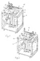
- a grinding arrangement for grinding the reverse side of electroplated stampers for the production of CD and DVD discs is represented in general by 10.
- the grinding arrangement 10 comprises a housing 12 with an upper plate 14 in which there is an opening 16 for an underlying trough 18.
- a chuck 20 mounted in such a way that it can rotate around an essentially vertical axis.
- the chuck 20 is arranged to hold, preferably by means of a vacuum, a stamper (not shown) which is to be ground.
- a grinding machine represented in general by 22 is mounted on a stand 24 which is mounted on the top side of a sliding table 26 designed as a plate.
- the grinding machine 22 has a vertically oriented grinding spindle 28 which passes closely through a hole or passage 30 in the sliding table 26.
- the sliding table 26 is mounted on the top side of the plate 14 in such a way that it can be moved in a linear direction by means of guides 27 between a rear position shown in Figure 1, in which the spindle 28 of the grinding machine can be inserted down into any one of three storage tubes 32, 34, 36 via openings 32a, 34a, 36a ( Figure 2) for replacing or exchanging different grinding tools and in which position a ground matrix can be removed from the chuck and a new one can be put on, and a position ( Figure 2) covering the trough 18, in which the sliding table 26 can cover the opening 16 like a lid such that it seals it by means of a seal 38 that circumscribes the trough opening 16.
- coolant and grinding fluid and grinding particles are prevented from splashing out of the trough and contaminating the surrounding environment and equipment.
- the housing 12 can contain various additional equipment, such as drive and control units for the grinding machine 22, the sliding table 26, the chuck 20, fluid pumps, etc, in addition to the storage tubes 32, 34, 36 for grinding tools.
Landscapes
- Engineering & Computer Science (AREA)
- Mechanical Engineering (AREA)
- Finish Polishing, Edge Sharpening, And Grinding By Specific Grinding Devices (AREA)
- Grinding-Machine Dressing And Accessory Apparatuses (AREA)
- Grinding Of Cylindrical And Plane Surfaces (AREA)
Applications Claiming Priority (2)
| Application Number | Priority Date | Filing Date | Title |
|---|---|---|---|
| SE0401204 | 2004-05-10 | ||
| SE0401204A SE525589C2 (sv) | 2004-05-10 | 2004-05-10 | Anordning för slipning av ett skivformigt element |
Publications (2)
| Publication Number | Publication Date |
|---|---|
| EP1595643A2 true EP1595643A2 (de) | 2005-11-16 |
| EP1595643A3 EP1595643A3 (de) | 2006-07-26 |
Family
ID=32390909
Family Applications (1)
| Application Number | Title | Priority Date | Filing Date |
|---|---|---|---|
| EP05103573A Withdrawn EP1595643A3 (de) | 2004-05-10 | 2005-04-29 | Vorrichtung zum Schleifen von einem Scheibenförmigenelement |
Country Status (2)
| Country | Link |
|---|---|
| EP (1) | EP1595643A3 (de) |
| SE (1) | SE525589C2 (de) |
Cited By (1)
| Publication number | Priority date | Publication date | Assignee | Title |
|---|---|---|---|---|
| CN105415114A (zh) * | 2015-11-06 | 2016-03-23 | 湘电风能有限公司 | 一种风力发电机组偏航制动盘表面修复装置 |
Family Cites Families (3)
| Publication number | Priority date | Publication date | Assignee | Title |
|---|---|---|---|---|
| US2080880A (en) * | 1935-12-10 | 1937-05-18 | Leitz Inc E | Polishing machine |
| US4499690A (en) * | 1983-03-10 | 1985-02-19 | E. D. Coddington Manufacturing Company | Split stations surface grinding apparatus |
| TW536752B (en) * | 2001-11-26 | 2003-06-11 | Chung Shan Inst Of Science | Compensation type CMP method and apparatus |
-
2004
- 2004-05-10 SE SE0401204A patent/SE525589C2/sv not_active IP Right Cessation
-
2005
- 2005-04-29 EP EP05103573A patent/EP1595643A3/de not_active Withdrawn
Cited By (1)
| Publication number | Priority date | Publication date | Assignee | Title |
|---|---|---|---|---|
| CN105415114A (zh) * | 2015-11-06 | 2016-03-23 | 湘电风能有限公司 | 一种风力发电机组偏航制动盘表面修复装置 |
Also Published As
| Publication number | Publication date |
|---|---|
| SE0401204D0 (sv) | 2004-05-10 |
| EP1595643A3 (de) | 2006-07-26 |
| SE0401204L (sv) | 2005-03-15 |
| SE525589C2 (sv) | 2005-03-15 |
Similar Documents
| Publication | Publication Date | Title |
|---|---|---|
| JP4342928B2 (ja) | 工作機械の工具交換装置 | |
| US20230405757A1 (en) | Barrier device used in the manufacture of a lapping plate, and related apparatuses and methods of making | |
| US7163441B2 (en) | Semiconductor wafer grinder | |
| CN223130198U (zh) | 一种通用型立式数控单面磨床 | |
| JP4382221B2 (ja) | 水没式切削装置 | |
| SE525589C2 (sv) | Anordning för slipning av ett skivformigt element | |
| CN216758636U (zh) | 一种眼镜自动焊接工作台 | |
| CN214923133U (zh) | 一种钛合金金属材料3d打印成品用的打磨设备 | |
| JP2021171881A (ja) | 切削装置及び載置プレート | |
| CN114161260B (zh) | 立式磨边倒角成型机 | |
| JPH0825219A (ja) | 研削盤 | |
| CN219665980U (zh) | 一种条纹表面加工装置 | |
| CN213507168U (zh) | 一种靶材位置可调整的溅射靶材基座 | |
| CN212351403U (zh) | 一种轮毂法兰外圈加工用倒角设备 | |
| JP2002086338A (ja) | ディスク研磨装置 | |
| CN216913223U (zh) | 立式磨边倒角成型机 | |
| CN220518954U (zh) | 一种抛光垫周转架 | |
| CN118122713B (zh) | 一种组合式激光清洗设备 | |
| CN215699865U (zh) | 一种防工件偏移的数控雕铣机 | |
| CN216913219U (zh) | 一种磨边倒角装置 | |
| CN211916500U (zh) | 一种抛光机用抛光铁盘存放架 | |
| CN215148112U (zh) | 一种凸轮分割器外壳旋转打磨治具 | |
| CN222038029U (zh) | 一种镜片高效率双面抛光机 | |
| CN118989367B (zh) | 一种大型阀体多角度加工自动车床 | |
| CN219113743U (zh) | 一种金属表面打磨机 |
Legal Events
| Date | Code | Title | Description |
|---|---|---|---|
| PUAI | Public reference made under article 153(3) epc to a published international application that has entered the european phase |
Free format text: ORIGINAL CODE: 0009012 |
|
| AK | Designated contracting states |
Kind code of ref document: A2 Designated state(s): AT BE BG CH CY CZ DE DK EE ES FI FR GB GR HU IE IS IT LI LT LU MC NL PL PT RO SE SI SK TR |
|
| AX | Request for extension of the european patent |
Extension state: AL BA HR LV MK YU |
|
| PUAL | Search report despatched |
Free format text: ORIGINAL CODE: 0009013 |
|
| AK | Designated contracting states |
Kind code of ref document: A3 Designated state(s): AT BE BG CH CY CZ DE DK EE ES FI FR GB GR HU IE IS IT LI LT LU MC NL PL PT RO SE SI SK TR |
|
| AX | Request for extension of the european patent |
Extension state: AL BA HR LV MK YU |
|
| RIC1 | Information provided on ipc code assigned before grant |
Ipc: B24B 41/02 20060101ALI20060619BHEP Ipc: B24B 37/04 20060101ALI20060619BHEP Ipc: B23Q 1/68 20060101ALI20060619BHEP Ipc: B23Q 1/58 20060101ALI20060619BHEP Ipc: B24B 7/02 20060101AFI20060619BHEP |
|
| AKX | Designation fees paid | ||
| REG | Reference to a national code |
Ref country code: DE Ref legal event code: 8566 |
|
| STAA | Information on the status of an ep patent application or granted ep patent |
Free format text: STATUS: THE APPLICATION IS DEEMED TO BE WITHDRAWN |
|
| 18D | Application deemed to be withdrawn |
Effective date: 20070127 |